2006 DODGE RAM SRT-10 engine wiring
[x] Cancel search: engine wiringPage 7 of 5267

When Monitored:
Ignition on.
Set Condition:
When the PCM recognizes the Auxiliary 5-volt Supply circuit voltage is toolow. One Trip Fault. ETC light is
flashing.
Possible Causes
(F856) AUXILIARY 5-VOLT SUPPLY SHORTED TO GROUND
SENSOR SHORTED TO GROUND
CAM POSITION SENSOR
PCM
Always perform the Pre-Diagnostic Troubleshooting procedure before proceeding. (Refer to 9 - ENGINE -
DIAGNOSIS AND TESTING).
Diagnostic Test
1.ACTIVE DTC
Ignition on, engine not running.
With a scan tool, read DTCs.
NOTE: Improperly installed aftermarket accessories can cause this DTC toset. Check for wiring added by
customer.
Is the DTC active at this time?
Ye s>>
Go To 2
No>>
Refer to the INTERMITTENT CONDITION Diagnostic Procedure.
Perform the POWERTRAIN VERIFICATION TEST. (Refer to 9 - ENGINE - STANDARD PROCEDURE)
2.(F856) AUXILIARY 5-VOLT SUPPLY SHORTED TO GROUND
Turn the ignition off.
Disconnect the C1 PCM harness connector.
Disconnect all the Sensors that share the (F856) Auxiliary 5-volt Supply
circuit.
Measure the resistance between ground and the (F856) Auxiliary 5-volt
Supply circuit in the CMP Sensor harness connector.
Istheresistancebelow100ohms?
Ye s>>
Repair the short to ground in the (F856) Auxiliary 5-volt
Supply circuit.
Perform the POWERTRAIN VERIFICATION TEST. (Refer to
9 - ENGINE - STANDARD PROCEDURE)
No>>
Go To 3
Page 10 of 5267

When Monitored:
Ignition on.
Set Condition:
When the PCM recognizes the Auxiliary 5-volt Supply circuit voltage is toohigh. One Trip Fault. ETC light is
flashing.
Possible Causes
(F856) AUXILIARY 5-VOLT SUPPLY SHORTED TO BATTERY VOLTAGE
PCM
Always perform the Pre-Diagnostic Troubleshooting procedure before proceeding. (Refer to 9 - ENGINE -
DIAGNOSIS AND TESTING).
Diagnostic Test
1.ACTIVE DTC
Ignition on, engine not running.
With a scan tool, read DTCs.
Is the DTC active at this time?
Ye s>>
Go To 2
No>>
Refer to the INTERMITTENT CONDITION Diagnostic Procedure.
Perform the POWERTRAIN VERIFICATION TEST. (Refer to 9 - ENGINE - STANDARD PROCEDURE)
2.(F856) AUXILIARY 5-VOLT SUPPLY SHORTED TO BATTERY VOLTAGE
Turn the ignition off.
Disconnect the C1 PCM harness connector.
Disconnect all the Sensors that share the (F856) Auxiliary 5-volt Supply
circuit.
NOTE: Improperly installed aftermarket accessories can cause this
DTC to set. Check for wiring added by customer.
Ignition on, engine not running.
Measure the voltage on the (F856) Auxiliary 5-volt Supply circuit at the
CMP Sensor harness connector.
Is the voltage above 0 volts?
Ye s>>
Repair the short to battery voltage in the (F856) Auxiliary
5-volt Supply circuit.
Perform the POWERTRAIN VERIFICATION TEST. (Refer to
9 - ENGINE - STANDARD PROCEDURE)
No>>
Go To 3
Page 21 of 5267
P0700-TRANSMISSION CONTROL SYSTEM (MIL REQUEST)
For a complete wiring diagramRefer to Section 8W.
When Monitored:
Ignition on and battery voltage greater than 10 volts.
Set Condition:
An active DTC is stored in the TCM. One Trip Fault. Three good trips to turn offtheMIL.
Possible Causes
DTC PRESENT IN THE TRANSMISSION CONTROL MODULE
Always perform the Pre-Diagnostic Troubleshooting procedure before proceeding. (Refer to 9 - ENGINE -
DIAGNOSIS AND TESTING).
Diagnostic Test
1.DTC PRESENT IN EATX CONTROLLER
This is an informational DTC letting you know that a DTC(s) is stored in the Transmission Control Module.
Erase this DTC from the PCM after all Transmission DTC(s) have been repaired.
Using a scan tool, read the Transmission Controller DTC and refer to the Transmission Category and perform the
appropriate symptom.
PCM Diagnostic Information complete.
Continue
Te s t C o m p l e t e .
Page 65 of 5267
When Monitored:
With the ignition on. Battery voltage greater than 10.4 volts. TIPM requesting A/C Clutch operation.
Set Condition:
An overcurrent condition is detected in the A/C Clutch control output circuit. One Trip Fault. Three good trips
to turn off the MIL.
Possible Causes
TERMINAL DAMAGE OR CORROSION
A/C CLUTCH GROUND HIGH RESISTANCE
(C3) A/C CLUTCH CONTROL OUTPUT CIRCUIT HIGH RESISTANCE
A/C COMPRESSOR CLUTCH
TIPM
Always perform the Pre-Diagnostic Troubleshooting procedure before proceeding. (Refer to 9 - ENGINE -
DIAGNOSIS AND TESTING).
Diagnostic Test
1.A/C CLUTCH OPERATION
Ignition on, engine not running.
With a scan tool in the TIPM Actuators, actuate the A/C Clutch.
Is the A/C Clutch actuating?
Ye s>>
Refer to the INTERMITTENT CONDITION Diagnostic Procedure.
Perform the POWERTRAIN VERIFICATION TEST. (Refer to 9 - ENGINE - STANDARD PROCEDURE)
No>>
Go To 2
2.VISUAL AND PHYSICAL CONNECTOR AND TERMINAL INSPECTION
Turn the ignition off.
Disconnect the TIPM C9 harness connector.
Disconnect the A/C Clutch harness connector.
Inspect the terminal and connector condition. Check for signs of corrosion build up or damage the would compro-
mise the terminal to controller pin connector.
NOTE: Make sure that all in-line connectors are inspected for corrosion and/or damage.
Visually inspect the wiring harness. Look for any chafed, pierced, pinched or partially broken wires hidden in the
wire insulation.
Were any of the above conditions found?
Ye s>>
Repair or replace as necessary.
Perform the POWERTRAIN VERIFICATION TEST. (Refer to 9 - ENGINE - STANDARD PROCEDURE)
No>>
Go To 3
Page 91 of 5267
When Monitored:
With the ignition on. Battery voltage greater than 10.4 volts. TIPM requesting Fuel Pump operation.
Set Condition:
An overcurrent condition is detected in the fuel pump control output circuit. One Trip Fault. Three good trips to
turn off the MIL.
Possible Causes
TERMINAL DAMAGE OR CORROSION
FUEL PUMP MOTOR GROUND HIGH RESISTANCE
(A109) FUEL PUMP CONTROL OUTPUT CIRCUIT HIGH RESISTANCE
FUEL PUMP MOTOR
TIPM
Always perform the Pre-Diagnostic Troubleshooting procedure before proceeding. (Refer to 9 - ENGINE -
DIAGNOSIS AND TESTING).
Diagnostic Test
1.FUEL PUMP OPERATION
Ignition on, engine not running.
With a scan tool in the TIPM Actuators, actuate the Fuel Pump.
Is the Fuel Pump operating?
Ye s>>
Refer to the INTERMITTENT CONDITION Diagnostic Procedure.
Perform the POWERTRAIN VERIFICATION TEST. (Refer to 9 - ENGINE - STANDARD PROCEDURE)
No>>
Go To 2
2.VISUAL AND PHYSICAL CONNECTOR AND TERMINAL INSPECTION
Turn the ignition off.
Disconnect the C10 TIPM harness connector.
Disconnect the Fuel Pump Module harness connector.
Inspect the terminal and connector condition. Check for signs of corrosion build up or damage the would compro-
mise the terminal to controller pin connector.
NOTE: Make sure that all in-line connectors are inspected for corrosion and/or damage.
Visually inspect the wiring harness. Look for any chafed, pierced, pinched or partially broken wires hidden in the
wire insulation.
Were any of the above conditions found?
Ye s>>
Repair or replace as necessary.
Perform the POWERTRAIN VERIFICATION TEST. (Refer to 9 - ENGINE - STANDARD PROCEDURE)
No>>
Go To 3
Page 98 of 5267
For a complete wiring diagramRefer to Section 8W.
Theory of Operation
When all criteria has been met, power is supplied to each MDS Solenoid when the engine is making a transition
from 8 cylinder mode to 4 cylinder mode. By actuating the solenoid, oil pressure is raised to the pair of lifters that
coincide with each particular solenoid. The oil pressure pushes in the locking pins that allows the lifter to collapse,
decoupling the valves and camshaft.
When Monitored:
Transition from 8 to 4 cylinder mode.
Set Condition:
The MDS fails to active and take place for cylinder 1. One trip fault.
Possible Causes
(K451) MDS SOLENOID NO.1 CONTROL SHORT TO GROUND
(K451) MDS SOLENOID NO.1 CONTROL OPEN
(Z42) GROUND CIRCUIT OPEN
INSUFFICIENT OIL PRESSURE ACTING ON THE LIFTER LOCKING PINS
OIL PASSAGES RESTRICTED
LIFTER
MDS SOLENOID NO.1
PCM
Always perform the Pre-Diagnostic Troubleshooting procedure before proceeding. (Refer to 9 - ENGINE -
DIAGNOSIS AND TESTING).
Diagnostic Test
1.ACTIVE DTC
Ignition on, engine not running.
With a scan tool, read DTCs.
Is the DTC active at this time?
Ye s>>
Go To 2
No>>
Refer to the INTERMITTENT CONDITION Diagnostic Procedure.
Perform the POWERTRAIN VERIFICATION TEST. (Refer to 9 - ENGINE - STANDARD PROCEDURE)
Page 103 of 5267
For a complete wiring diagramRefer to Section 8W.
Theory of Operation
When all criteria has been met, power is supplied to each MDS Solenoid when the engine is making a transition
from 8 cylinder mode to 4 cylinder mode. By actuating the solenoid, oil pressure is raised to the pair of lifters that
coincide with each particular solenoid. The oil pressure pushes in the locking pins that allows the lifter to collapse,
decoupling the valves and camshaft.
When Monitored:
Transition from 8 to 4 cylinder mode.
Set Condition:
The MDS fails to active and take place for cylinder 4. One trip fault.
Possible Causes
(K452) MDS SOLENOID NO.4 CONTROL SHORT TO GROUND
(K452) MDS SOLENOID NO.4 CONTROL OPEN
(Z42) GROUND CIRCUIT OPEN
INSUFFICIENT OIL PRESSURE ACTING ON THE LIFTER LOCKING PINS
OIL PASSAGES RESTRICTED
LIFTER
MDS SOLENOID NO.4
PCM
Always perform the Pre-Diagnostic Troubleshooting procedure before proceeding. (Refer to 9 - ENGINE -
DIAGNOSIS AND TESTING).
Diagnostic Test
1.ACTIVE DTC
Ignition on, engine not running.
With a scan tool, read DTCs.
Is the DTC active at this time?
Ye s>>
Go To 2
No>>
Refer to the INTERMITTENT CONDITION Diagnostic Procedure.
Perform the POWERTRAIN VERIFICATION TEST. (Refer to 9 - ENGINE - STANDARD PROCEDURE)
Page 108 of 5267
For a complete wiring diagramRefer to Section 8W.
Theory of Operation
When all criteria has been met, power is supplied to each MDS Solenoid when the engine is making a transition
from 8 cylinder mode to 4 cylinder mode. By actuating the solenoid, oil pressure is raised to the pair of lifters that
coincide with each particular solenoid. The oil pressure pushes in the locking pins that allows the lifter to collapse,
decoupling the valves and camshaft.
When Monitored:
Transition from 8 to 4 cylinder mode.
Set Condition:
The MDS fails to active and take place for cylinder 6. One trip fault.
Possible Causes
(K453) MDS SOLENOID NO.6 CONTROL SHORT TO GROUND
(K453) MDS SOLENOID NO.6 CONTROL OPEN
(Z42) GROUND CIRCUIT OPEN
INSUFFICIENT OIL PRESSURE ACTING ON THE LIFTER LOCKING PINS
OIL PASSAGES RESTRICTED
LIFTER
MDS SOLENOID NO.6
PCM
Always perform the Pre-Diagnostic Troubleshooting procedure before proceeding. (Refer to 9 - ENGINE -
DIAGNOSIS AND TESTING).
Diagnostic Test
1.ACTIVE DTC
Ignition on, engine not running.
With a scan tool, read DTCs.
Is the DTC active at this time?
Ye s>>
Go To 2
No>>
Refer to the INTERMITTENT CONDITION Diagnostic Procedure.
Perform the POWERTRAIN VERIFICATION TEST. (Refer to 9 - ENGINE - STANDARD PROCEDURE)
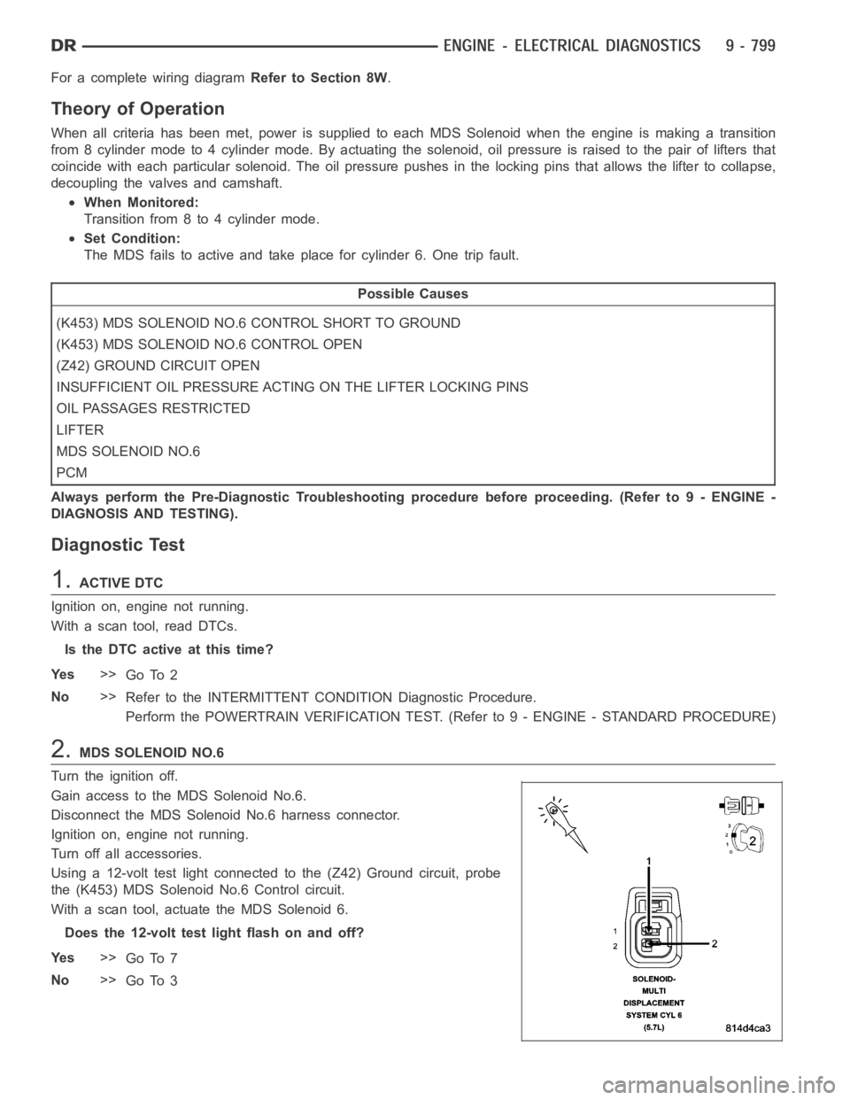
2.MDS SOLENOID NO.6
Turn the ignition off.
Gain access to the MDS Solenoid No.6.
Disconnect the MDS Solenoid No.6 harness connector.
Ignition on, engine not running.
Turn off all accessories.
Using a 12-volt test light connected to the (Z42) Ground circuit, probe
the (K453) MDS Solenoid No.6 Control circuit.
With a scan tool, actuate the MDS Solenoid 6.
Does the 12-volt test light flash on and off?
Ye s>>
Go To 7
No>>
Go To 3