2006 DODGE RAM SRT-10 automatic transmission
[x] Cancel search: automatic transmissionPage 3433 of 5267
INSTALLATION
CAUTION: The primary oil filter seal MUST be fully
installed flush against the oil pump body. DO NOT
install the seal onto the filter neck and attempt to
install the filter and seal as an assembly. Damage
to the transmission will result.
1. If necessary, install a new primary oil filter seal in
the oil pump inlet bore. Seat the seal in the bore
with a suitable tool (appropriately sized drift or
socket, the butt end of a hammer, or other suitable
tool).
2. Place replacement filter in position on valve body
and into the oil pump.
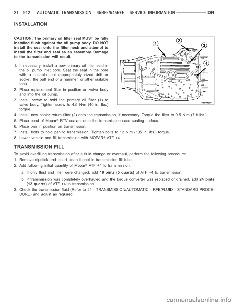
3. Install screw to hold the primary oil filter (1) to
valve body. Tighten screw to 4.5 Nꞏm (40 in. lbs.)
torque.
4. Install new cooler return filter (2) onto the transmission, if necessary. Torque the filter to 9.5 Nꞏm (7 ft.lbs.).
5. Place bead of Mopar
RTV sealant onto the transmission case sealing surface.
6. Place pan in position on transmission.
7. Install bolts to hold pan to transmission. Tighten bolts to 12 Nꞏm (105 in. lbs.) torque.
8. Lower vehicle and fill transmission with MOPAR
AT F + 4 .
TRANSMISSION FILL
To avoid overfilling transmission after a fluid change or overhaul, perform the following procedure:
1. Remove dipstick and insert clean funnel in transmission fill tube.
2. Add following initial quantity of Mopar
ATF+4totransmission:
a. If only fluid and filter were changed, add10 pints (5 quarts)of ATF +4 to transmission.
b. If transmission was completely overhauled and the torque converter wasreplaced or drained, add24 pints
(12 quarts)ofATF+4totransmission.
3. Check the transmission fluid (Refer to 21 - TRANSMISSION/AUTOMATIC - RFE/FLUID - STANDARD PROCE-
DURE) and adjust as required.
Page 3435 of 5267
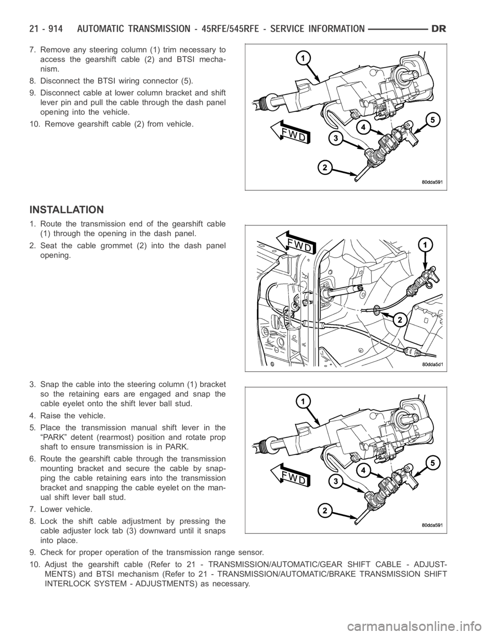
7. Remove any steering column (1) trim necessary to
access the gearshift cable (2) and BTSI mecha-
nism.
8. Disconnect the BTSI wiring connector (5).
9. Disconnect cable at lower column bracket and shift
lever pin and pull the cable through the dash panel
opening into the vehicle.
10. Remove gearshift cable (2) from vehicle.
INSTALLATION
1. Route the transmission end of the gearshift cable
(1) through the opening in the dash panel.
2. Seat the cable grommet (2) into the dash panel
opening.
3. Snap the cable into the steering column (1) bracket
so the retaining ears are engaged and snap the
cable eyelet onto the shift lever ball stud.
4. Raise the vehicle.
5. Place the transmission manual shift lever in the
“PARK” detent (rearmost) position and rotate prop
shaft to ensure transmission is in PARK.
6. Route the gearshift cable through the transmission
mounting bracket and secure the cable by snap-
ping the cable retaining ears into the transmission
bracket and snapping the cable eyelet on the man-
ual shift lever ball stud.
7. Lower vehicle.
8. Lock the shift cable adjustment by pressing the
cable adjuster lock tab (3) downward until it snaps
into place.
9. Check for proper operation of the transmission range sensor.
10. Adjust the gearshift cable (Refer to 21 - TRANSMISSION/AUTOMATIC/GEAR SHIFT CABLE - ADJUST-
MENTS) and BTSI mechanism (Refer to 21 - TRANSMISSION/AUTOMATIC/BRAKE TRANSMISSION SHIFT
INTERLOCK SYSTEM - ADJUSTMENTS) as necessary.
Page 3446 of 5267
ASSEMBLY
NOTE: Install all new seals and o-rings onto the input shaft and input hub. The o-rings on the input hub are
color coded. Be sure to install the correct o-ring in the correct location.
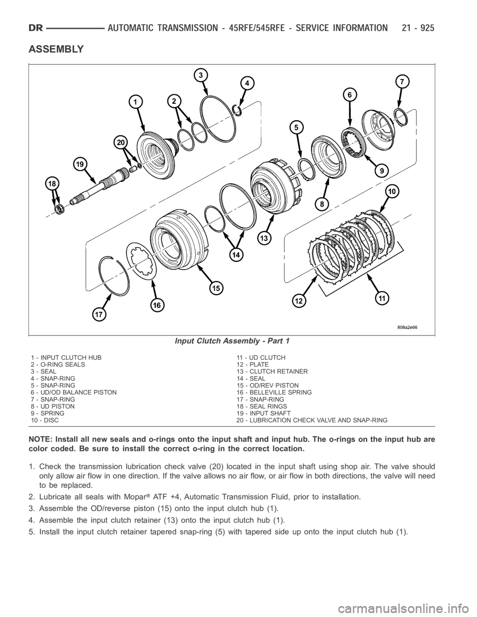
1. Check the transmission lubrication check valve (20) located in the input shaft using shop air. The valve should
only allow air flow in one direction. If the valve allows no air flow, or air flow in both directions, the valve will need
to be replaced.
2. Lubricate all seals with Mopar
ATF +4, Automatic Transmission Fluid, prior to installation.
3. Assemble the OD/reverse piston (15) onto the input clutch hub (1).
4. Assemble the input clutch retainer (13) onto the input clutch hub (1).
5. Install the input clutch retainer tapered snap-ring (5) with tapered side up onto the input clutch hub (1).
Input Clutch Assembly - Part 1
1 - INPUT CLUTCH HUB 11 - UD CLUTCH
2 - O-RING SEALS 12 - PLATE
3 - SEAL 13 - CLUTCH RETAINER
4 - SNAP-RING 14 - SEAL
5 - SNAP-RING 15 - OD/REV PISTON
6 - UD/OD BALANCE PISTON 16 - BELLEVILLE SPRING
7 - SNAP-RING 17 - SNAP-RING
8 - UD PISTON 18 - SEAL RINGS
9 - SPRING 19 - INPUT SHAFT
10 - DISC 20 - LUBRICATION CHECK VALVE AND SNAP-RING
Page 3459 of 5267
ASSEMBLY
1. Check the bleed orifice to ensure that it is not
plugged or restricted.
2. Install a new seal on the low/reverse piston. Lubri-
cate the seal with Mopar
ATF +4, Automatic
Transmission Fluid, prior to installation.
3. Install the low/reverse piston into the low/reverse
clutch retainer.
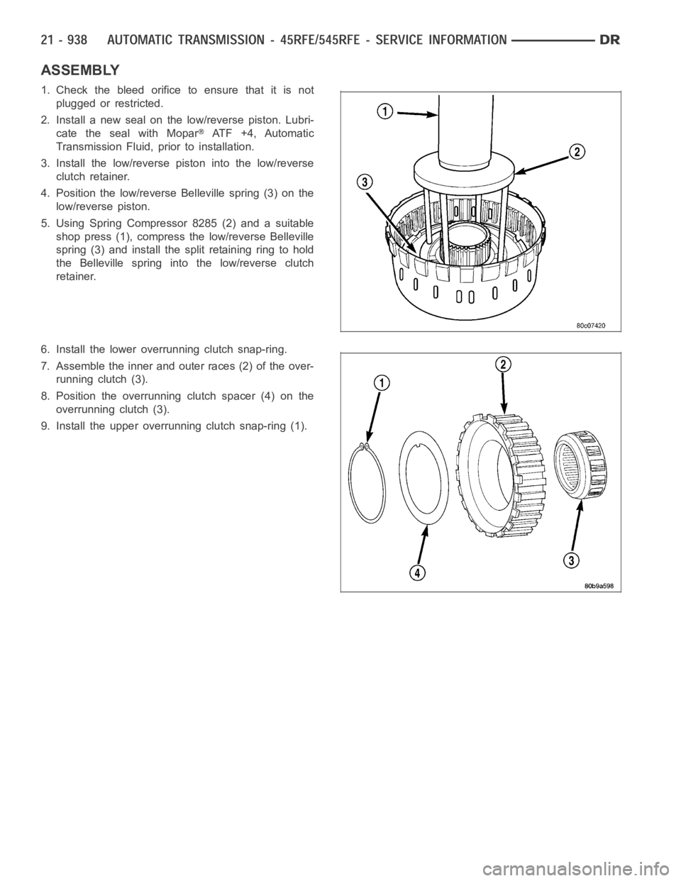
4. Position the low/reverse Belleville spring (3) on the
low/reverse piston.
5. Using Spring Compressor 8285 (2) and a suitable
shop press (1), compress the low/reverse Belleville
spring (3) and install the split retaining ring to hold
the Belleville spring into the low/reverse clutch
retainer.
6. Install the lower overrunning clutch snap-ring.
7. Assemble the inner and outer races (2) of the over-
running clutch (3).
8. Position the overrunning clutch spacer (4) on the
overrunning clutch (3).
9. Install the upper overrunning clutch snap-ring (1).
Page 3463 of 5267
OPERATION
As the torque converter rotates, the converter hub rotates the oil pump drive gear. As the drive gear rotates both
driven gears, a vacuum is created when the gear teeth come out of mesh. This suction draws fluid through the
pump inlet from the oil pan. As the gear teeth come back into mesh, pressurized fluid is forced into the pump outlet
and to the oil pump valves.
At low speeds, both sides of the pump supply fluid to the transmission. As the speed of the torque converter
increases, the flow from both sides increases until the flow from the primary side alone is sufficient to meet system
demands. At this point, the check valve located between the two pumps closes. The secondary side is shut down
and the primary side supplies all the fluid to the transmission.
CONVERTER CLUTCH SWITCH VALVE
The converter clutch switch valve is used to control the hydraulic pressure supplied to the front (OFF) side of the
torque converter clutch.
CONVERTER CLUTCH REGULATOR VALVE
The converter clutch regulator valve is used to control the hydraulic pressure supplied to the back (ON) side of the
torque converter clutch.
TORQUE CONVERTER LIMIT VALVE
The torque converter limit valve serves to limit the available line pressure to the torque converter clutch.
STANDARD PROCEDURE - OIL PUMP VOLUME CHECK
Measuring the oil pump output volume will determine if sufficient oil flowto the transmission oil cooler exists, and
whether or not an internal transmission failure is present.
Verify that the transmission fluid is at the proper level. Refer to the Fluid Level Check procedure in this section. If
necessary, fill the transmission to the proper level with Mopar
ATF +4, Automatic Transmission Fluid.
1. Disconnect theTo coolerline at the cooler inlet and place a collecting container under the disconnected line.
CAUTION: With the fluid set at the proper level, fluid collection should not exceed (1) quart or internal dam-
age to the transmission may occur.
2. Run the engineat 1800 rpm, with the shift selector in neutral. Verify that the transmission fluid temperature is
below 104.5° C (220° F) for this test.
3. If one quart of transmission fluid is collected in the container in 30 seconds or less, oil pump flow volume is
within acceptable limits. If fluid flow is intermittent, or it takes more than 30 seconds to collect one quart of fluid,
refer to the Hydraulic Pressure tests in this section for further diagnosis.
4. Re-connect theTo c o o l e rline to the transmission cooler inlet.
5. Refill the transmission to proper level.
Page 3480 of 5267
MECHANISM-SHIFT
DESCRIPTION
The gear shift mechanism provides six shift positions which are:
Park (P)
Reverse (R)
Neutral (N)
Drive (D)
Manual second (2)
Manual low (1)
OPERATION
MANUAL LOW (1) range provides first gear only. Overrun braking is also provided in this range. MANUAL SECOND
(2) range provides first and second gear only.
DRIVE range provides FIRST, SECOND, THIRD, OVERDRIVE FOURTH, and OVERDRIVE FIFTH (if applicable)
gear ranges. The shift into OVERDRIVE FOURTH and FIFTH (if applicable) gear ranges occurs only after the trans-
mission has completed the shift into D THIRD gear range. No further movement of the shift mechanism is required
to complete the 3-4 or 4-5 (if applicable) shifts.
The FOURTH and FIFTH (if applicable) gear upshifts occur automatically when the overdrive selector switch is in
the ON position. No upshift to FOURTH or FIFTH (if applicable) gears will occur if any of the following are true:
The transmission fluid temperature is below 10° C (50° F) or above 121° C (250° F).
The shift to THIRD is not yet complete.
Vehicle speed is too low for the 3-4 or 4-5 (if applicable) shifts to occur.
Upshifts into FOURTH or FIFTH (if applicable) will be delayed when the transmission fluid temperature is below 4.5°
C(40°F)orabove115.5°C(240°F).
Page 3487 of 5267
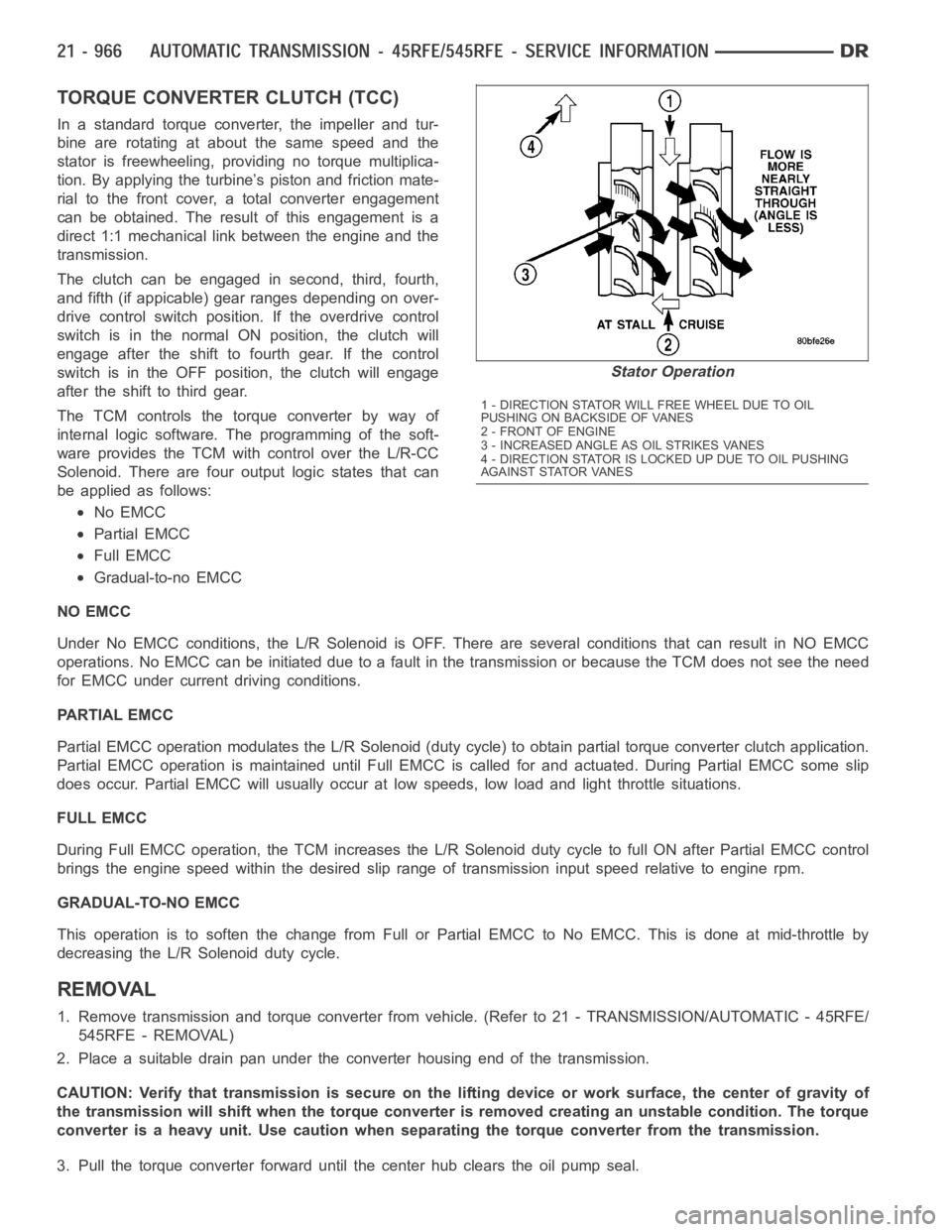
TORQUE CONVERTER CLUTCH (TCC)
In a standard torque converter, the impeller and tur-
bine are rotating at about the same speed and the
stator is freewheeling, providing no torque multiplica-
tion. By applying the turbine’s piston and friction mate-
rial to the front cover, a total converter engagement
can be obtained. The result of this engagement is a
direct 1:1 mechanical link between the engine and the
transmission.
The clutch can be engaged in second, third, fourth,
and fifth (if appicable) gear ranges depending on over-
drive control switch position. If the overdrive control
switch is in the normal ON position, the clutch will
engage after the shift to fourth gear. If the control
switch is in the OFF position, the clutch will engage
after the shift to third gear.
The TCM controls the torque converter by way of
internal logic software. The programming of the soft-
ware provides the TCM with control over the L/R-CC
Solenoid. There are four output logic states that can
be applied as follows:
No EMCC
Partial EMCC
Full EMCC
Gradual-to-no EMCC
NO EMCC
Under No EMCC conditions, the L/R Solenoid is OFF. There are several conditions that can result in NO EMCC
operations. No EMCC can be initiated due to a fault in the transmission or because the TCM does not see the need
for EMCC under current driving conditions.
PARTIAL EMCC
Partial EMCC operation modulates the L/R Solenoid (duty cycle) to obtain partial torque converter clutch application.
Partial EMCC operation is maintaineduntil Full EMCC is called for and actuated. During Partial EMCC some slip
does occur. Partial EMCC will usually occur at low speeds, low load and light throttle situations.
FULL EMCC
During Full EMCC operation, the TCM increases the L/R Solenoid duty cycle to full ON after Partial EMCC control
brings the engine speed within the desired slip range of transmission input speed relative to engine rpm.
GRADUAL-TO-NO EMCC
This operation is to soften the change from Full or Partial EMCC to No EMCC. This is done at mid-throttle by
decreasing the L/R Solenoid duty cycle.
REMOVAL
1. Remove transmission and torque converter from vehicle. (Refer to 21 - TRANSMISSION/AUTOMATIC - 45RFE/
545RFE - REMOVAL)
2. Place a suitable drain pan under the converter housing end of the transmission.
CAUTION: Verify that transmission is secure on the lifting device or work surface, the center of gravity of
the transmission will shift when the torque converter is removed creatingan unstable condition. The torque
converter is a heavy unit. Use caution when separating the torque converter from the transmission.
3. Pull the torque converter forward until the center hub clears the oil pumpseal.
Stator Operation
1 - DIRECTION STATOR WILL FREE WHEEL DUE TO OIL
PUSHING ON BACKSIDE OF VANES
2-FRONTOFENGINE
3 - INCREASED ANGLE AS OIL STRIKES VANES
4 - DIRECTION STATOR IS LOCKED UP DUE TO OIL PUSHING
AGAINST STATOR VANES
Page 3492 of 5267
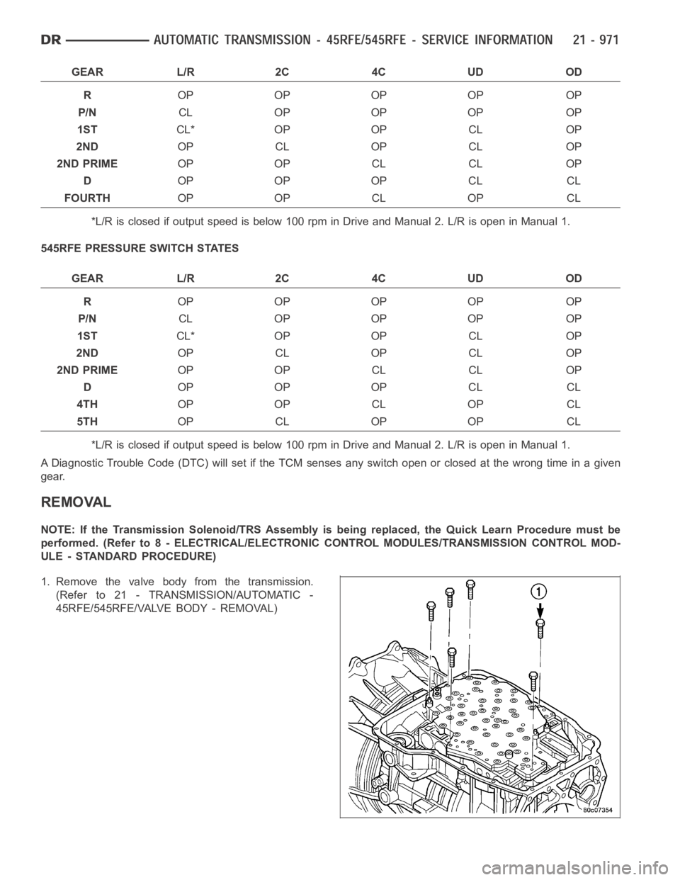
GEAR L/R 2C 4C UD OD
ROP OP OP OP OP
P/NCL OP OP OP OP
1STCL* OP OP CL OP
2NDOP CL OP CL OP
2ND PRIMEOP OP CL CL OP
DOP OP OP CL CL
FOURTHOP OP CL OP CL
*L/R is closed if output speed is below 100 rpm in Drive and Manual 2. L/R is open in Manual 1.
545RFE PRESSURE SWITCH STATES
GEAR L/R 2C 4C UD OD
ROP OP OP OP OP
P/NCL OP OP OP OP
1STCL* OP OP CL OP
2NDOP CL OP CL OP
2ND PRIMEOP OP CL CL OP
DOP OP OP CL CL
4THOP OP CL OP CL
5THOP CL OP OP CL
*L/R is closed if output speed is below 100 rpm in Drive and Manual 2. L/R is open in Manual 1.
A Diagnostic Trouble Code (DTC) will set if the TCM senses any switch open orclosed at the wrong time in a given
gear.
REMOVAL
NOTE: If the Transmission Solenoid/TRS Assembly is being replaced, the Quick Learn Procedure must be
performed. (Refer to 8 - ELECTRICAL/ELECTRONIC CONTROL MODULES/TRANSMISSION CONTROL MOD-
ULE - STANDARD PROCEDURE)
1. Remove the valve body from the transmission.
(Refer to 21 - TRANSMISSION/AUTOMATIC -
45RFE/545RFE/VALVE BODY - REMOVAL)