2006 DODGE RAM SRT-10 airbag
[x] Cancel search: airbagPage 5099 of 5267
DUCT-INSTRUMENT PANEL
REMOVAL
WARNING: On vehicles equipped with airbags, disable the airbag system before attempting any steering
wheel, steering column, or instrument panel component diagnosis or service. Disconnect and isolate the
battery negative (ground) cable, then wait two minutes for the airbag system capacitor to discharge before
performing further diagnosis or service. This is the only sure way to disable the airbag system. Failure to
take the proper precautions could result in an accidental airbag deployment and possible personal injury or
death.
NOTE: Take the proper precautions to protect the instrument panel from cosmetic damage.
1. Remove the instrument panel and place it on a
workbench (Refer to 23 - BODY/INSTRUMENT
PANEL/INSTRUMENT PANEL ASSEMBLY -
REMOVAL).
2. Remove the radio (Refer to 8 - ELECTRICAL/AU-
DIO/RADIO - REMOVAL).
3. Remove the defroster duct (Refer to 24 - HEATING
& AIR CONDITIONING/DISTRIBUTION/DUCT-DE-
FROSTER - REMOVAL).
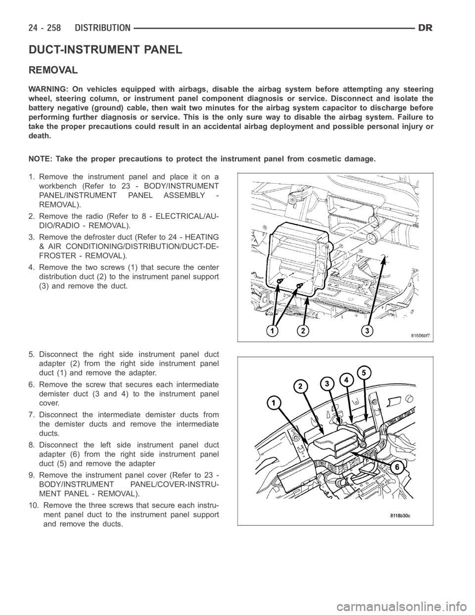
4. Remove the two screws (1) that secure the center
distribution duct (2) to the instrument panel support
(3) and remove the duct.
5. Disconnect the right side instrument panel duct
adapter (2) from the right side instrument panel
duct (1) and remove the adapter.
6. Remove the screw that secures each intermediate
demister duct (3 and 4) to the instrument panel
cover.
7. Disconnect the intermediate demister ducts from
the demister ducts and remove the intermediate
ducts.
8. Disconnect the left side instrument panel duct
adapter (6) from the right side instrument panel
duct (5) and remove the adapter
9. Remove the instrument panel cover (Refer to 23 -
BODY/INSTRUMENT PANEL/COVER-INSTRU-
MENT PANEL - REMOVAL).
10. Remove the three screws that secure each instru-
ment panel duct to the instrument panel support
and remove the ducts.
Page 5101 of 5267
DUCT-INSTRUMENT PANEL DEMISTER
REMOVAL
WARNING: On vehicles equipped with airbags, disable the airbag system before attempting any steering
wheel, steering column, or instrument panel component diagnosis or service. Disconnect and isolate the
battery negative (ground) cable, then wait two minutes for the airbag system capacitor to discharge before
performing further diagnosis or service. This is the only sure way to disable the airbag system. Failure to
take the proper precautions could result in an accidental airbag deployment and possible personal injury or
death.
NOTE: Take the proper precautions to protect the instrument panel from cosmetic damage.
1. Remove the instrument panel and place it on a
workbench (Refer to 23 - BODY/INSTRUMENT
PANEL/INSTRUMENT PANEL ASSEMBLY -
REMOVAL).
2. Remove the radio (Refer to 8 - ELECTRICAL/AU-
DIO/RADIO - REMOVAL).
3. Remove the defroster duct (Refer to 24 - HEATING
& AIR CONDITIONING/DISTRIBUTION/DUCT-DE-
FROSTER - REMOVAL).
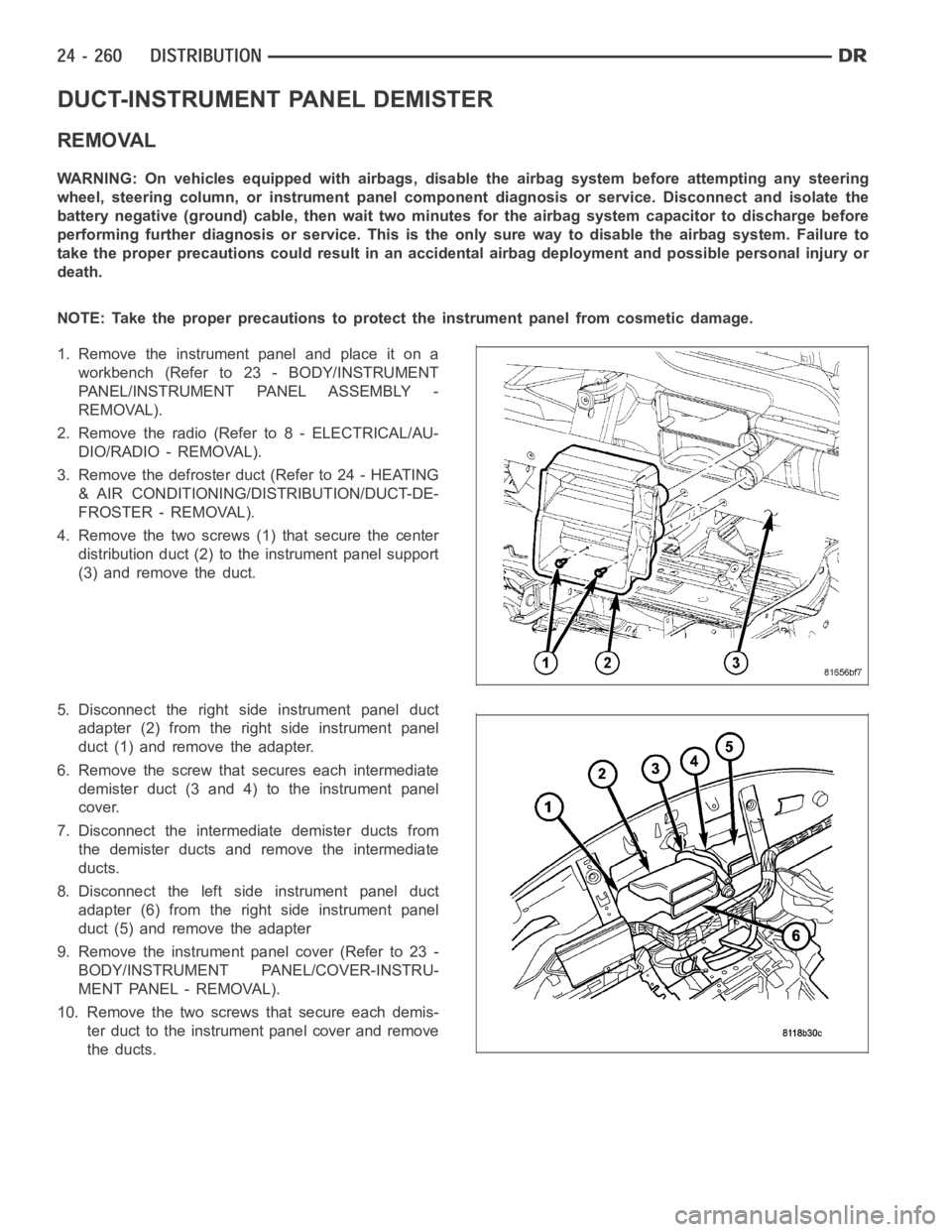
4. Remove the two screws (1) that secure the center
distribution duct (2) to the instrument panel support
(3) and remove the duct.
5. Disconnect the right side instrument panel duct
adapter (2) from the right side instrument panel
duct (1) and remove the adapter.
6. Remove the screw that secures each intermediate
demister duct (3 and 4) to the instrument panel
cover.
7. Disconnect the intermediate demister ducts from
the demister ducts and remove the intermediate
ducts.
8. Disconnect the left side instrument panel duct
adapter (6) from the right side instrument panel
duct (5) and remove the adapter
9. Remove the instrument panel cover (Refer to 23 -
BODY/INSTRUMENT PANEL/COVER-INSTRU-
MENT PANEL - REMOVAL).
10. Remove the two screwsthat secure each demis-
ter duct to the instrument panel cover and remove
the ducts.
Page 5104 of 5267
REMOVAL
HVAC HOUSING ASSEMBLY
WARNING: Refer to the applicable warnings and cautions for this system before performing the following
operation (Refer to 24 - HEATING & AIR CONDITIONING/PLUMBING - WARNINGS) and (Refer to 24 - HEAT-
ING & AIR CONDITIONING/PLUMBING - CAUTIONS). Failure to follow the warnings and cautions could result
in possible personal injury or death.
WARNING: On vehicles equipped with airbags, disable the airbag system before attempting any steering
wheel, steering column, or instrument panel component diagnosis or service. Disconnect and isolate the
negative battery (ground) cable, then wait two minutes for the airbag system capacitor to discharge before
performing further diagnosis or service. This is the only sure way to disable the airbag system. Failure to
take the proper precautions could result in accidental airbag deploymentand possible personal injury or
death.
NOTE: The HVAC housing must be removedfrom the vehicle and disassembled for service of the A/C evap-
orator, evaporator temperature sensor, mode-air and blend-air doors.
1. Recover the refrigerant from the refrigerant system
(Refer to 24 - HEATING & AIR CONDITIONING/
PLUMBING - STANDARD PROCEDURE -
REFRIGERANT SYSTEM RECOVERY).
2. Drain the engine cooling system (Refer to 7 -
COOLING - STANDARD PROCEDURE - COOL-
ING SYSTEM DRAIN).
3. Disconnect and isolate the negative battery cable.
4. Disconnect the A/C liquid line and the A/C accumu-
lator from the A/C evaporator (Refer to 24 - HEAT-
ING & AIR CONDITIONING/PLUMBING/LINE-A/C
LIQUID - REMOVAL) and (Refer to 24 - HEATING
& AIR CONDITIONING/PLUMBING/ACCUMULA-
TOR-A/C - REMOVAL).
5. Disconnect the heater hoses from the heater core
tubes.
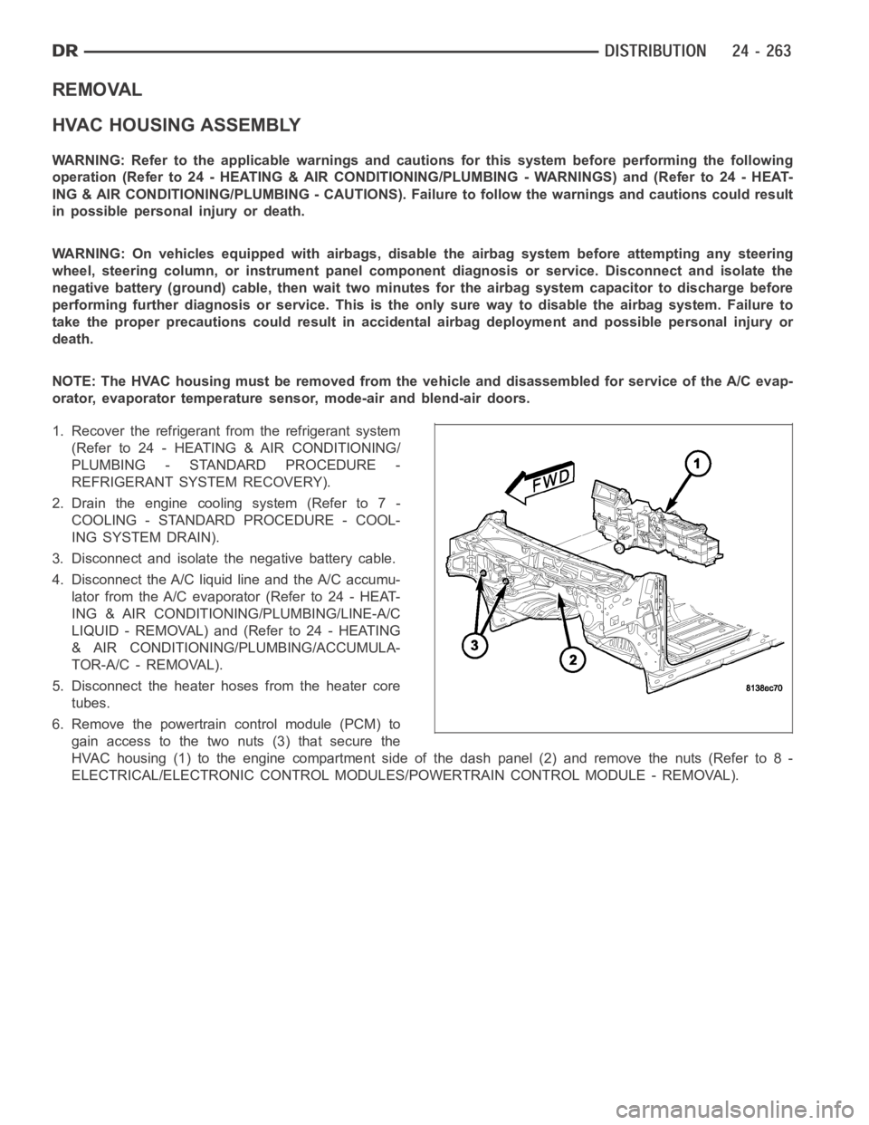
6. Remove the powertrain control module (PCM) to
gain access to the two nuts (3) that secure the
HVAC housing (1) to the engine compartment side of the dash panel (2) and remove the nuts (Refer to 8 -
ELECTRICAL/ELECTRONIC CONTROL MODULES/POWERTRAIN CONTROL MODULE - REMOVAL).
Page 5105 of 5267
7. On Mega Cab models, remove the floor console
duct (Refer to 24 - HEATING & AIR CONDITION-
ING/DISTRIBUTION/DUCT-FLOOR CONSOLE -
REMOVAL).
8. Remove the instrument panel from the passenger
compartment (Refer to 23 - BODY/INSTRUMENT
PANEL ASSEMBLY - REMOVAL).
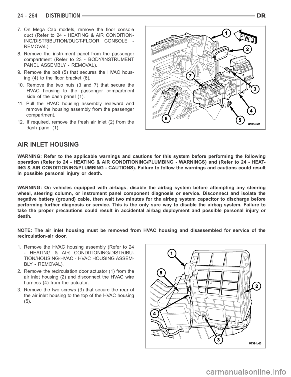
9. Remove the bolt (5) that secures the HVAC hous-
ing (4) to the floor bracket (6).
10. Remove the two nuts (3 and 7) that secure the
HVAC housing to the passenger compartment
side of the dash panel (1).
11. Pull the HVAC housing assembly rearward and
remove the housing assembly from the passenger
compartment.
12. If required, remove the fresh air inlet (2) from the
dash panel (1).
AIR INLET HOUSING
WARNING: Refer to the applicable warnings and cautions for this system before performing the following
operation (Refer to 24 - HEATING & AIR CONDITIONING/PLUMBING - WARNINGS) and (Refer to 24 - HEAT-
ING & AIR CONDITIONING/PLUMBING - CAUTIONS). Failure to follow the warnings and cautions could result
in possible personal injury or death.
WARNING: On vehicles equipped with airbags, disable the airbag system before attempting any steering
wheel, steering column, or instrument panel component diagnosis or service. Disconnect and isolate the
negative battery (ground) cable, then wait two minutes for the airbag system capacitor to discharge before
performing further diagnosis or service. This is the only sure way to disable the airbag system. Failure to
take the proper precautions could result in accidental airbag deploymentand possible personal injury or
death.
NOTE: The air inlet housing must be removed from HVAC housing and disassembled for service of the
recirculation-air door.
1. Remove the HVAC housing assembly (Refer to 24
- HEATING & AIR CONDITIONING/DISTRIBU-
TION/HOUSING-HVAC - HVAC HOUSING ASSEM-
BLY - REMOVAL).
2. Remove the recirculation door actuator (1) from the
air inlet housing (2) and disconnect the HVAC wire
harness (4) from the actuator.
3. Remove the two screws (3) that secure the rear of
the air inlet housing to the top of the HVAC housing
(5).
Page 5121 of 5267
MOTOR-BLOWER
DESCRIPTION
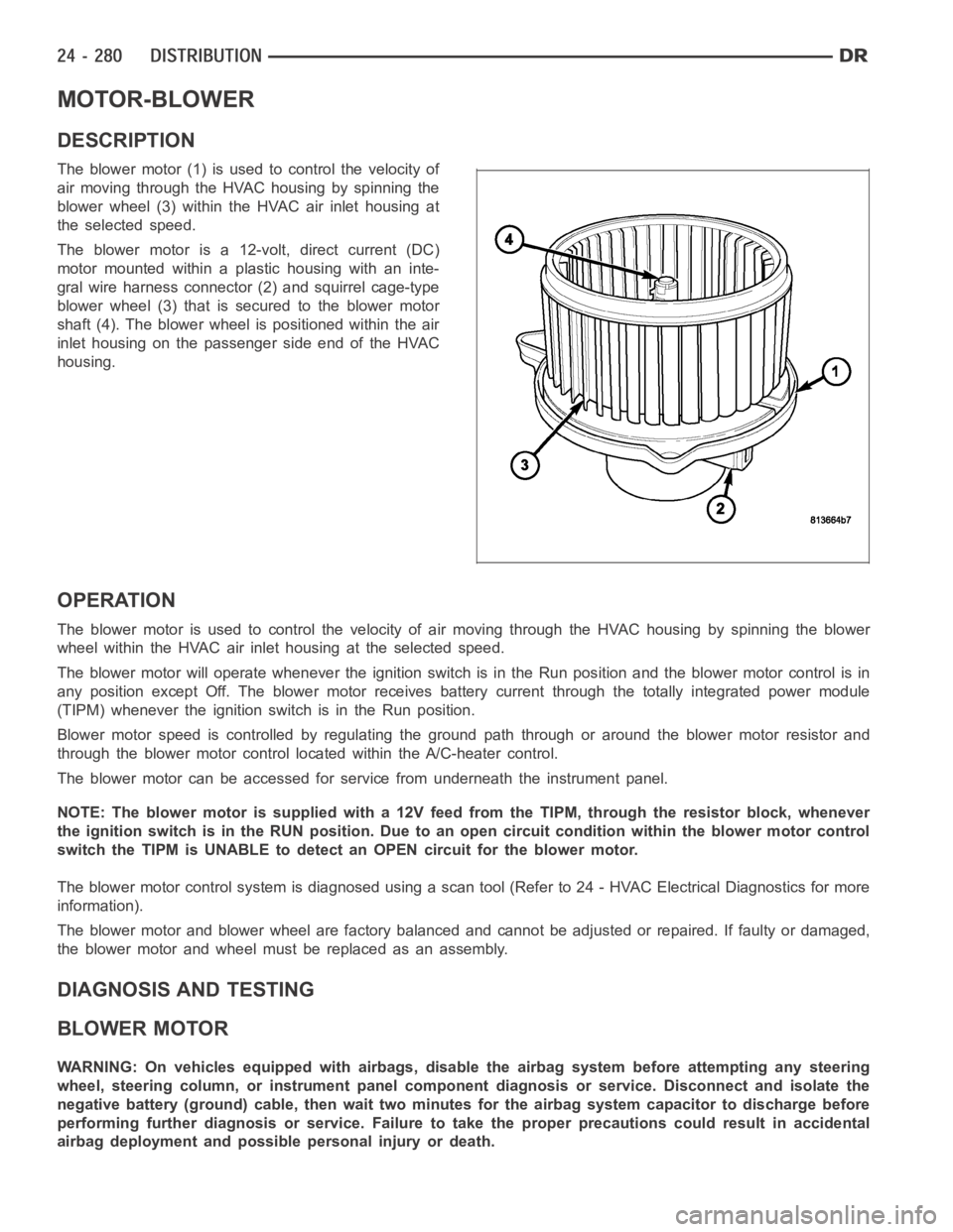
The blower motor (1) is used to control the velocity of
air moving through the HVAC housing by spinning the
blower wheel (3) within the HVAC air inlet housing at
the selected speed.
The blower motor is a 12-volt, direct current (DC)
motormountedwithinaplastichousingwithaninte-
gral wire harness connector (2) and squirrel cage-type
blower wheel (3) that is secured to the blower motor
shaft (4). The blower wheel is positioned within the air
inlet housing on the passenger side end of the HVAC
housing.
OPERATION
The blower motor is used to control the velocity of air moving through the HVAC housing by spinning the blower
wheel within the HVAC air inlet housing at the selected speed.
The blower motor will operate whenever the ignition switch is in the Run position and the blower motor control is in
any position except Off. The blower motor receives battery current through the totally integrated power module
(TIPM) whenever the ignition switch is in the Run position.
Blower motor speed is controlled by regulating the ground path through or around the blower motor resistor and
through the blower motor control located within the A/C-heater control.
The blower motor can be accessed for service from underneath the instrument panel.
NOTE: The blower motor is supplied with a 12V feed from the TIPM, through theresistor block, whenever
the ignition switch is in the RUN position. Due to an open circuit conditionwithin the blower motor control
switch the TIPM is UNABLE to detect an OPEN circuit for the blower motor.
The blower motor control system is diagnosed using a scan tool (Refer to 24 -HVAC Electrical Diagnostics for more
information).
The blower motor and blower wheel are factory balanced and cannot be adjusted or repaired. If faulty or damaged,
the blower motor and wheel must be replaced as an assembly.
DIAGNOSIS AND TESTING
BLOWER MOTOR
WARNING: On vehicles equipped with airbags, disable the airbag system before attempting any steering
wheel, steering column, or instrument panel component diagnosis or service. Disconnect and isolate the
negative battery (ground) cable, then wait two minutes for the airbag system capacitor to discharge before
performing further diagnosis or service. Failure to take the proper precautions could result in accidental
airbag deployment and possible personal injury or death.
Page 5151 of 5267
CORE-HEATER
DESCRIPTION
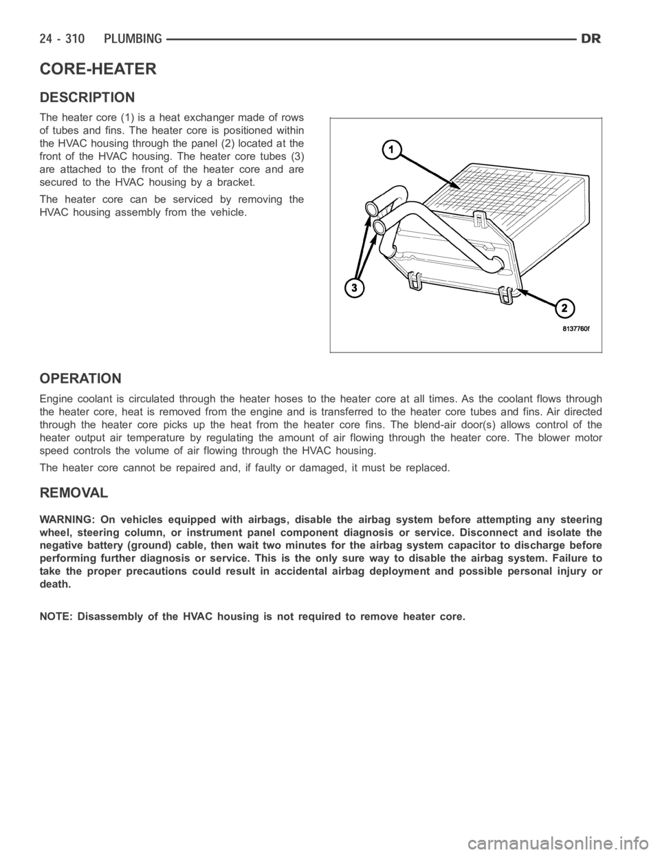
The heater core (1) is a heat exchanger made of rows
of tubes and fins. The heater core is positioned within
the HVAC housing through the panel (2) located at the
front of the HVAC housing. The heater core tubes (3)
are attached to the front of the heater core and are
secured to the HVAC housing by a bracket.
The heater core can be serviced by removing the
HVAC housing assembly from the vehicle.
OPERATION
Engine coolant is circulated through the heater hoses to the heater core atall times. As the coolant flows through
the heater core, heat is removed from the engine and is transferred to the heater core tubes and fins. Air directed
through the heater core picks up the heat from the heater core fins. The blend-air door(s) allows control of the
heater output air temperature by regulating the amount of air flowing through the heater core. The blower motor
speed controls the volume of air flowing through the HVAC housing.
The heater core cannot be repaired and, if faulty or damaged, it must be replaced.
REMOVAL
WARNING: On vehicles equipped with airbags, disable the airbag system before attempting any steering
wheel, steering column, or instrument panel component diagnosis or service. Disconnect and isolate the
negative battery (ground) cable, then wait two minutes for the airbag system capacitor to discharge before
performing further diagnosis or service. This is the only sure way to disable the airbag system. Failure to
take the proper precautions could result in accidental airbag deploymentand possible personal injury or
death.
NOTE: Disassembly of the HVAC housing is not required to remove heater core.