2006 DODGE RAM SRT-10 check oil
[x] Cancel search: check oilPage 3511 of 5267
Theory of Operation
The Transmission Temperature Sensor is used to sense when the transmissiontemperatureistoohotortoocoldto
operate overdrive and/or the torque convertor clutch. When the transmission sensor detects a temperature below 0°
C (32° F), overdrive and the torque convertor clutch are disabled. When thedetected temperature is above 127° C
(260° F), overdrive is disabled and 3rd gear with TCC is engaged, this strategy is used to increase transmission
fluid flow to help cool the transmission.
When Monitored:
Continuously with the ignition on and the engine running.
Set Condition:
The DTC will set after two consecutive trips in which the transmission oil temperature is greater than 5° C (40°
F) and the transmission oil temperature does not rise more than 8° C (16° F) after 20 minutes of run time with
a vehicle speed greater than 48 Kmh (30 mph). The DTC will also set if the engine temperature is greater than
38° C (100° F) with the transmission oil temperature greater than 127° C (260° F).
Possible Causes
OTHER TRANSMISSION DTC’S SET
INTERMITTENT TRANSMISSION TEMPERATURE SENSOR
TRANSMISSION TEMPERATURE SENSOR
Always perform the Pre-Diagnostic Troubleshooting procedure before proceeding. (Refer to 21 - TRANSMIS-
SION/TRANSAXLE/AUTOMATIC - 48RE - STANDARD PROCEDURE)
Diagnostic Test
1.CHECK IF THE DTC IS CURRENT
Ignition on, engine not running.
With the scan tool, read Engine DTCs.
Record the Freeze Frame data for the reported DTC.
With the scan tool, erase DTCs.
Turn the ignition off to the lock position.
Using the Freeze Frame data recorded earlier, try to duplicate the conditions in which the DTC originally set.
NOTE: It may be necessary to road test the vehicle to duplicate the originalset conditions.
With the scan tool, read Engine DTCs.
Did the DTC reset?
Ye s>>
Go To 2
No>>
Go To 6
2.CHECK FOR OTHER TRANSMISSION DTCS
Does the scan tool show any Park/Neutral DTCs?
Ye s>>
Refer to the Transmission category and perform the appropriate symptom(s).
No>>
Go To 3
Page 3513 of 5267
Turn the ignition off to the lock position.
Remove the Transmission Oil Pan per the Service Information. (Refer to 21 -TRANSMISSION/TRANSAXLE/AU-
TOMATIC - 48RE/FLUID - STANDARD PROCEDURE)
Disconnect the Governor Pressure Sensor harness connector internal to the transmission.
NOTE: Check connectors - Clean/repair as necessary
Measure the resistance of the Transmission Temperature Sensor between the (T54) Transmission Temperature Sen-
sor Signal circuit and the (K900) Sensor Ground circuit.
Using the chart at the chart above, compare the Temperature Sensor temperature to the correlating resistance
value.
Is the resistance within the specified range when the sensor is at the giventemperature?
Ye s>>
Te s t C o m p l e t e .
No>>
Replace the Governor Pressure/Transmission Temperature Sensor per the Service Information. (Refer to
21 - TRANSMISSION/TRANSAXLE/AUTOMATIC - 48RE/GOVERNOR PRESSURE SENSOR-
REMOVAL)
Perform RE TRANSMISSION VERIFICATION TEST VER - 1 (GAS). (Refer to 21 - TRANSMISSION/
TRANSAXLE/AUTOMATIC - 48RE - STANDARD PROCEDURE)
6.INTERMITTENT WIRING AND CONNECTORS
The conditions necessary to set this DTC are not present at this time.
Use the Freeze Frame Data to help duplicate the conditions in which the DTC originally set. Pay particular attention
to the DTC set conditions, such as, VSS, MAP, ECT, and Load.
Using the schematics as a guide, visually inspect the related wiring harness. Look for any chafed, pierced, pinched,
or partially broken wires.
Visually inspect the related wiring harness connectors. Look for broken,bent, pushed out, or corroded terminals.
Wiggle the wiring and connectors while checking for any possible open or shorted circuits.
Check for any Service Information Tune-ups or Technical Service Bulletins that may apply.
Were there any problems found?
Ye s>>
Repair as necessary.
Perform RE TRANSMISSION VERIFICATION TEST VER - 1 (GAS). (Refer to 21 - TRANSMISSION/
TRANSAXLE/AUTOMATIC - 48RE - STANDARD PROCEDURE)
No>>
Te s t C o m p l e t e .
Page 3517 of 5267
4.CHECK THE (T54) TRANSMISSION TEMPERATURE SENSOR SIGNAL CIRCUIT FOR A SHORTTO
GROUND INSIDE TRANSMISSION
Remove the Transmission Oil Pan perthe Service Information. (Refer to
21 - TRANSMISSION/TRANSAXLE/AUTOMATIC - 48RE/FLUID -
STANDARD PROCEDURE)
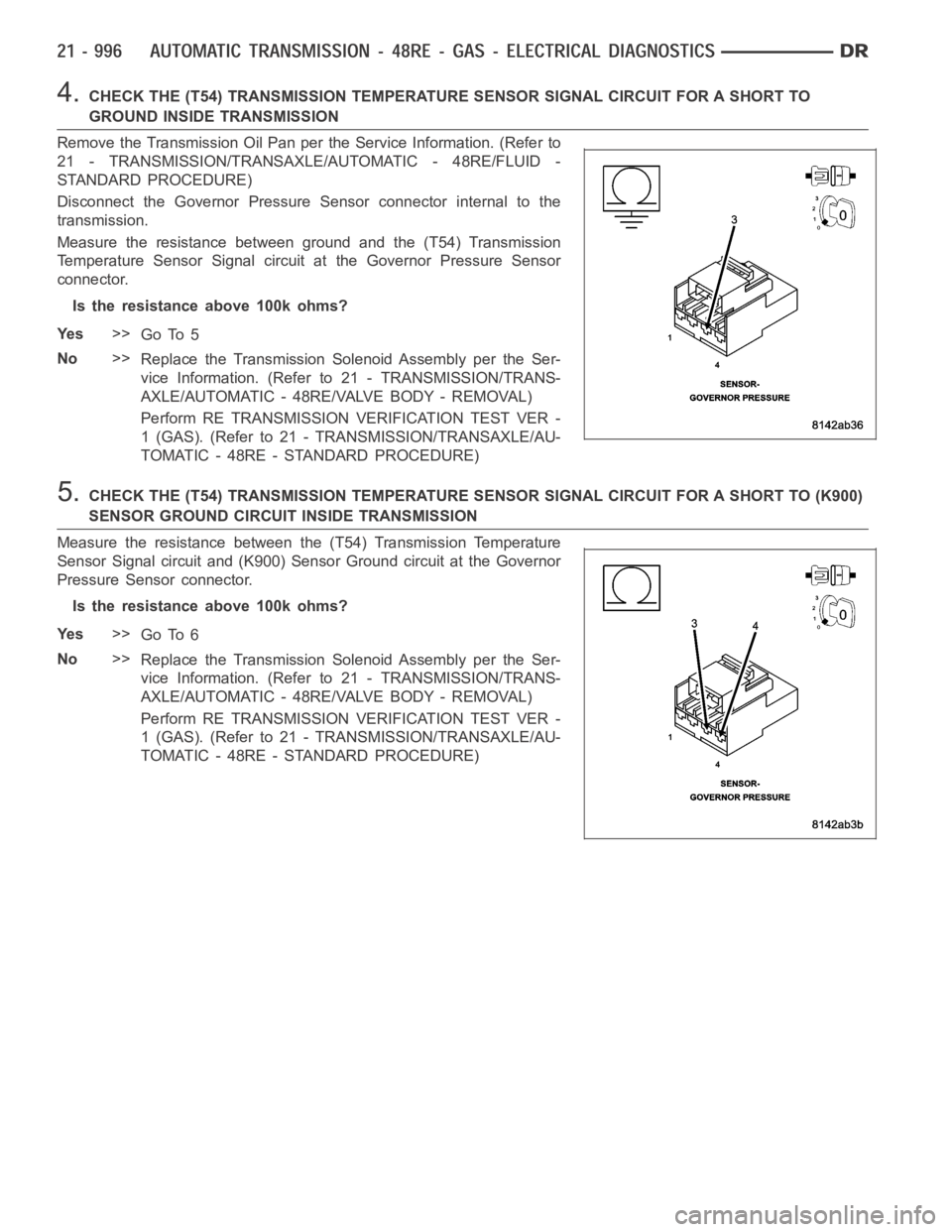
Disconnect the Governor Pressure Sensor connector internal to the
transmission.
Measure the resistance between ground and the (T54) Transmission
Temperature Sensor Signal circuit at the Governor Pressure Sensor
connector.
Is the resistance above 100k ohms?
Ye s>>
Go To 5
No>>
Replace the Transmission Solenoid Assembly per the Ser-
vice Information. (Refer to 21 - TRANSMISSION/TRANS-
AXLE/AUTOMATIC - 48RE/VALVE BODY - REMOVAL)
Perform RE TRANSMISSION VERIFICATION TEST VER -
1 (GAS). (Refer to 21 - TRANSMISSION/TRANSAXLE/AU-
TOMATIC - 48RE - STANDARD PROCEDURE)
5.CHECK THE (T54) TRANSMISSION TEMPERATURE SENSOR SIGNAL CIRCUIT FOR A SHORT TO (K900)
SENSOR GROUND CIRCUIT INSIDE TRANSMISSION
Measure the resistance between the (T54) Transmission Temperature
Sensor Signal circuit and (K900) Sensor Ground circuit at the Governor
Pressure Sensor connector.
Is the resistance above 100k ohms?
Ye s>>
Go To 6
No>>
Replace the Transmission Solenoid Assembly per the Ser-
vice Information. (Refer to 21 - TRANSMISSION/TRANS-
AXLE/AUTOMATIC - 48RE/VALVE BODY - REMOVAL)
Perform RE TRANSMISSION VERIFICATION TEST VER -
1 (GAS). (Refer to 21 - TRANSMISSION/TRANSAXLE/AU-
TOMATIC - 48RE - STANDARD PROCEDURE)
Page 3524 of 5267
6.CHECK THE (T54) TRANSMISSION TEMPERATURE SENSOR SIGNAL CIRCUIT FOR A SHORTTOTHE
(F856) 5-VOLT SUPPLY CIRCUIT INTERNAL TO THE TRANSMISSION
Remove the Transmission Oil Pan. (Refer to 21 - TRANSMISSION/
TRANSAXLE/AUTOMATIC - 48RE/FLUID - STANDARD PROCEDURE)
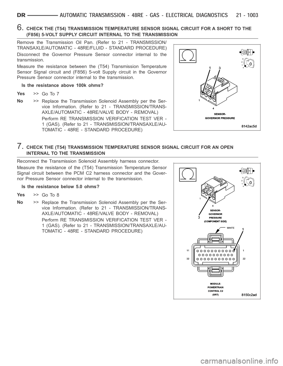
Disconnect the Governor Pressure Sensor connector internal to the
transmission.
Measure the resistance between the (T54) Transmission Temperature
Sensor Signal circuit and (F856) 5-volt Supply circuit in the Governor
Pressure Sensor connector internal to the transmission.
Is the resistance above 100k ohms?
Ye s>>
Go To 7
No>>
Replace the Transmission Solenoid Assembly per the Ser-
vice Information. (Refer to 21 - TRANSMISSION/TRANS-
AXLE/AUTOMATIC - 48RE/VALVE BODY - REMOVAL)
Perform RE TRANSMISSION VERIFICATION TEST VER -
1 (GAS). (Refer to 21 - TRANSMISSION/TRANSAXLE/AU-
TOMATIC - 48RE - STANDARD PROCEDURE)
7.CHECK THE (T54) TRANSMISSION TEMPERATURE SENSOR SIGNAL CIRCUIT FOR AN OPEN
INTERNAL TO THE TRANSMISSION
Reconnect the Transmission Solenoid Assembly harness connector.
Measure the resistance of the (T54) Transmission Temperature Sensor
Signal circuit between the PCM C2 harness connector and the Gover-
nor Pressure Sensor connector internal to the transmission.
Is the resistance below 5.0 ohms?
Ye s>>
Go To 8
No>>
Replace the Transmission Solenoid Assembly per the Ser-
vice Information. (Refer to 21 - TRANSMISSION/TRANS-
AXLE/AUTOMATIC - 48RE/VALVE BODY - REMOVAL)
Perform RE TRANSMISSION VERIFICATION TEST VER -
1 (GAS). (Refer to 21 - TRANSMISSION/TRANSAXLE/AU-
TOMATIC - 48RE - STANDARD PROCEDURE)
Page 3527 of 5267
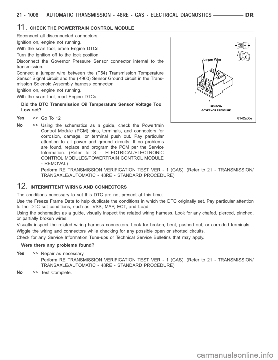
11 .CHECK THE POWERTRAIN CONTROL MODULE
Reconnect all disconnected connectors.
Ignition on, engine not running.
With the scan tool, erase Engine DTCs.
Turn the ignition off to the lock position.
Disconnect the Governor Pressure Sensor connector internal to the
transmission.
Connect a jumper wire between the (T54) Transmission Temperature
Sensor Signal circuit and the (K900) Sensor Ground circuit in the Trans-
mission Solenoid Assembly harness connector.
Ignition on, engine not running.
With the scan tool, read Engine DTCs.
Did the DTC Transmission Oil Temperature Sensor Voltage Too
Low set?
Ye s>>
Go To 12
No>>
Using the schematics as a guide, check the Powertrain
Control Module (PCM) pins, terminals, and connectors for
corrosion, damage, or terminal push out. Pay particular
attention to all power and ground circuits. If no problems
are found, replace and program the PCM per the Service
Information. (Refer to 8 - ELECTRICAL/ELECTRONIC
CONTROL MODULES/POWERTRAIN CONTROL MODULE
- REMOVAL)
Perform RE TRANSMISSION VERIFICATION TEST VER - 1 (GAS). (Refer to 21 - TRANSMISSION/
TRANSAXLE/AUTOMATIC - 48RE - STANDARD PROCEDURE)
12.INTERMITTENT WIRING AND CONNECTORS
The conditions necessary to set this DTC are not present at this time.
Use the Freeze Frame Data to help duplicate the conditions in which the DTC originally set. Pay particular attention
to the DTC set conditions, such as, VSS, MAP, ECT, and Load
Using the schematics as a guide, visually inspect the related wiring harness. Look for any chafed, pierced, pinched,
or partially broken wires.
Visually inspect the related wiring harness connectors. Look for broken,bent, pushed out, or corroded terminals.
Wiggle the wiring and connectors while checking for any possible open or shorted circuits.
Check for any Service Information Tune-ups or Technical Service Bulletins that may apply.
Were there any problems found?
Ye s>>
Repair as necessary.
Perform RE TRANSMISSION VERIFICATION TEST VER - 1 (GAS). (Refer to 21 - TRANSMISSION/
TRANSAXLE/AUTOMATIC - 48RE - STANDARD PROCEDURE)
No>>
Te s t C o m p l e t e .
Page 3536 of 5267
4.CHECK IF THE DTC IS CURRENT
With the scan tool, read Engine DTCs.
Record the Freeze Frame data for the reported DTC.
With the scan tool, erase DTCs.
Turn the ignition off to the lock position.
Using the Freeze Frame data recorded earlier, try to duplicate the conditions in which the DTC originally set.
NOTE: It may be necessary to road test the vehicle to duplicate the originalset conditions.
With the scan tool, read Engine DTCs.
Did the DTC reset?
Ye s>>
Go To 5
No>>
Go To 9
5.PERFORM TCC SYSTEM TEST
With the scan tool, perform the TCC System Test.
Follow the instructions on the screen.
Did the engine stall?
Ye s>>
Go To 6
No>>
Go To 7
6.PERFORM GOV AND 3-4 SHIFT VALVE SYSTEM TEST
With the scan tool, perform the Gov and 3-4 Shift Valve System Test.
Follow the instructions on the screen.
Did the engine stall?
Ye s>>
Go To 8
No>>
Go To 7
7.CHECK THE COOLER OUT PRESSURE
Turn the ignition off to the lock position.
Connect a pressure gauge to the transmission cooler out port with a “T” connector. (Refer to 21 - TRANSMISSION/
TRANSAXLE/AUTOMATIC - 48RE - DIAGNOSIS AND TESTING)
Start the engine, with the scan tool, perform the TCC System Test.
Did the cooler out pressure on the gauge increase when the TCC was actuated?
Ye s>>
Remove the transmission oil pump and inspect the reaction shaft, input shaft and input shaft seals for
damage or wear and repair or replace as necessary. Replace the Torque Convertor.
Perform RE TRANSMISSION VERIFICATION TEST VER - 1 (GAS). (Refer to 21 - TRANSMISSION/
TRANSAXLE/AUTOMATIC - 48RE - STANDARD PROCEDURE)
No>>
Remove the Valve Body and inspect for an internal blockage or an internal leak in the TCC hydraulic
circuit. Repair as necessary. (Refer to 21 - TRANSMISSION/TRANSAXLE/AUTO M AT I C - 4 8 R E / VA LV E
BODY - REMOVAL)
Perform RE TRANSMISSION VERIFICATION TEST VER - 1 (GAS). (Refer to 21 - TRANSMISSION/
TRANSAXLE/AUTOMATIC - 48RE - STANDARD PROCEDURE)
Page 3549 of 5267
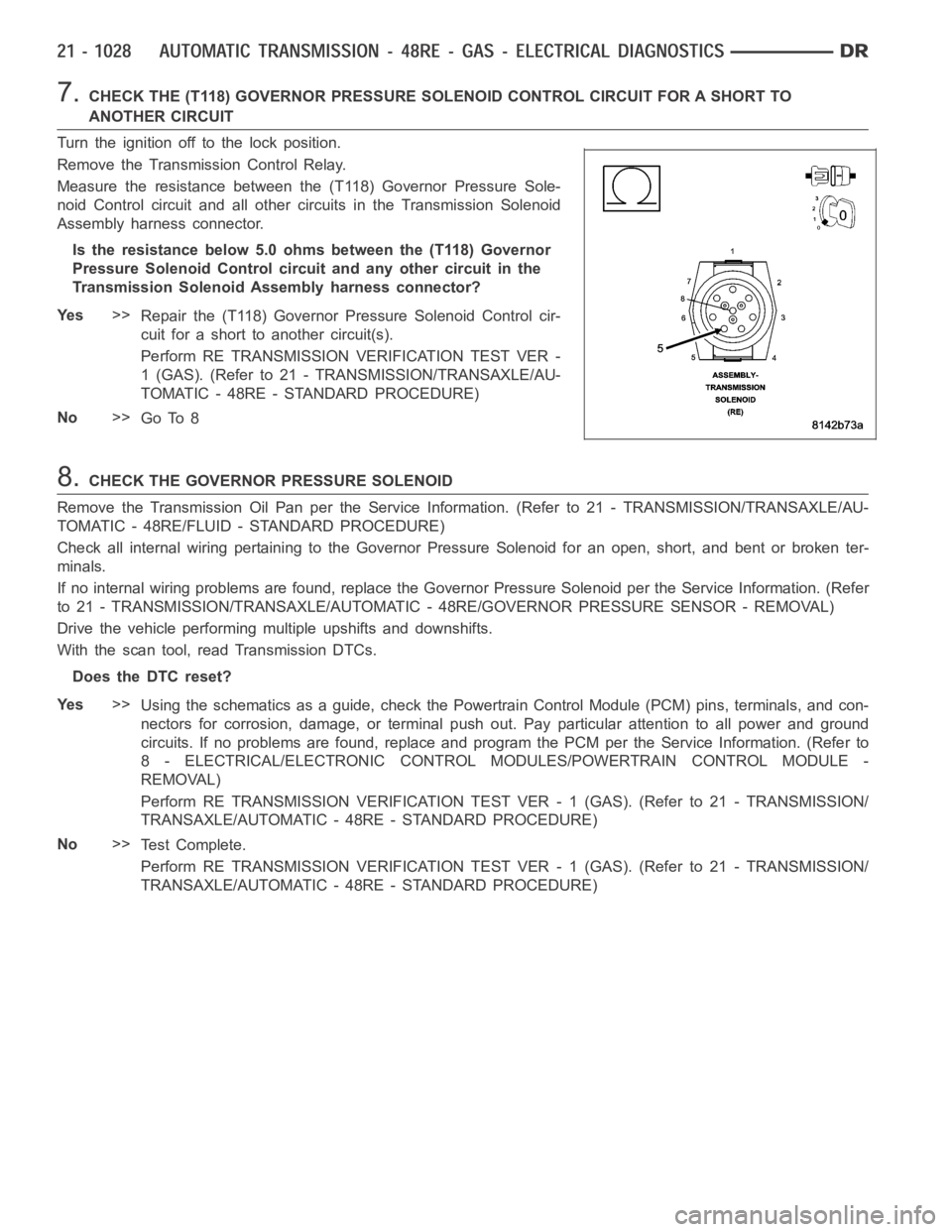
7.CHECK THE (T118) GOVERNOR PRESSURE SOLENOID CONTROL CIRCUIT FOR A SHORT TO
ANOTHER CIRCUIT
Turn the ignition off to the lock position.
Remove the Transmission Control Relay.
Measure the resistance between the (T118) Governor Pressure Sole-
noid Control circuit and all other circuits in the Transmission Solenoid
Assembly harness connector.
Is the resistance below 5.0 ohms between the (T118) Governor
Pressure Solenoid Control circuit and any other circuit in the
Transmission Solenoid Assembly harness connector?
Ye s>>
Repair the (T118) Governor Pressure Solenoid Control cir-
cuit for a short to another circuit(s).
Perform RE TRANSMISSION VERIFICATION TEST VER -
1 (GAS). (Refer to 21 - TRANSMISSION/TRANSAXLE/AU-
TOMATIC - 48RE - STANDARD PROCEDURE)
No>>
Go To 8
8.CHECK THE GOVERNOR PRESSURE SOLENOID
Remove the Transmission Oil Pan per the Service Information. (Refer to 21 -TRANSMISSION/TRANSAXLE/AU-
TOMATIC - 48RE/FLUID - STANDARD PROCEDURE)
Check all internal wiring pertaining to the Governor Pressure Solenoid for an open, short, and bent or broken ter-
minals.
If no internal wiring problems are found, replace the Governor Pressure Solenoid per the Service Information. (Refer
to 21 - TRANSMISSION/TRANSAXLE/AUTOMATIC - 48RE/GOVERNOR PRESSURE SENSOR - REMOVAL)
Drive the vehicle performing multiple upshifts and downshifts.
With the scan tool, read Transmission DTCs.
Does the DTC reset?
Ye s>>
Using the schematics as a guide, check the Powertrain Control Module (PCM)pins, terminals, and con-
nectors for corrosion, damage, or terminal push out. Pay particular attention to all power and ground
circuits. If no problems are found, replace and program the PCM per the Service Information. (Refer to
8 - ELECTRICAL/ELECTRONIC CONTROL MODULES/POWERTRAIN CONTROL MODULE -
REMOVAL)
Perform RE TRANSMISSION VERIFICATION TEST VER - 1 (GAS). (Refer to 21 - TRANSMISSION/
TRANSAXLE/AUTOMATIC - 48RE - STANDARD PROCEDURE)
No>>
Te s t C o m p l e t e .
Perform RE TRANSMISSION VERIFICATION TEST VER - 1 (GAS). (Refer to 21 - TRANSMISSION/
TRANSAXLE/AUTOMATIC - 48RE - STANDARD PROCEDURE)
Page 3564 of 5267
NOTE: The governor pressure should rise above 138 kPa (20 PSI). Shortly after the O/D pressure should
rise above 276 kPa (40 PSI).
Did the pressures act as previously described?
Ye s>>
Go To 4
No>>
Go To 5
4.CHECK THE TRANSMISSION OIL CONDITION
Turn the ignition off to the lock position.
Remove the transmission oil pan and inspect for excessive debris and burntoil.
Is the oil burnt or does the transmission oil pan contain excessive debris?
Ye s>>
Repair the transmission as necessary. Refer to the Service Informtion forthe proper repair procedures.
(Refer to 21 - TRANSMISSION/TRANSAXLE/AUTOMATIC - 48RE - DIAGNOSIS AND TESTING)
Perform RE TRANSMISSION VERIFICATION TEST VER - 1 (GAS). (Refer to 21 - TRANSMISSION/
TRANSAXLE/AUTOMATIC - 48RE - STANDARD PROCEDURE)
No>>
Go To 6
5.CHECK THE GOVERNOR AND OVERDRIVE PRESSURE AFTER REPLACEMENT OF THE 3-4 SHIFT
SOLENOID
Turn the ignition off to the lock position.
Replace the 3-4 Shift Solenoid per the Service Information. (Refer to 21 - TRANSMISSION/TRANSAXLE/AUTO-
MATIC - 48RE/VALVE BODY - DISASSEMBLY)
With the pressure gauges still attached, start the engine and allow the transmission temperature to rise to normal
operating temperature.
CAUTION: Apply the parking brake.
Firmly apply the brakesand place the gear selector in Drive.
While observing the pressure gauges, with the scan tool, select 4th gear from the Gov and 3-4 Shift Valve Test.
NOTE: The governor pressure should rise to above 138 kPa (20 PSI). Shortly after the O/D pressure should
rise above 276 kPa (40 PSI).
Did the pressures act as previously described?
Ye s>>
Te s t C o m p l e t e .
Perform RE TRANSMISSION VERIFICATION TEST VER - 1 (DIESEL). (Refer to 21 - TRANSMISSION/
TRANSAXLE/AUTOMATIC - 48RE - STANDARD PROCEDURE)
No>>
Overhaul the transmission per the Service Information. Pay attention to seals and clutches related to the
OD clutch.
Perform RE TRANSMISSION VERIFICATION TEST VER - 1 (GAS). (Refer to 21 - TRANSMISSION/
TRANSAXLE/AUTOMATIC - 48RE - STANDARD PROCEDURE)