Page 1776 of 5267
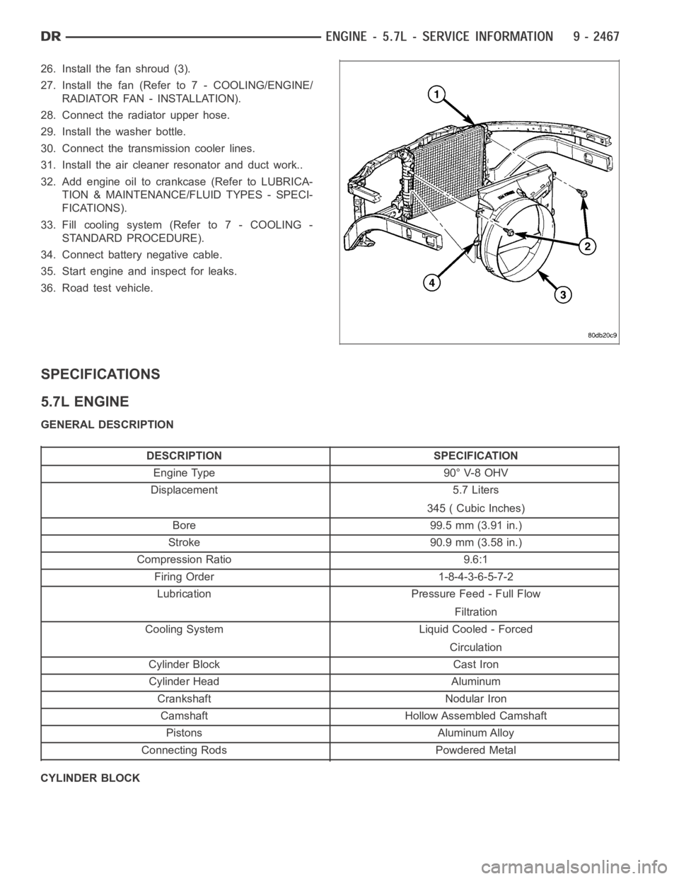
26. Install the fan shroud (3).
27. Install the fan (Refer to 7 - COOLING/ENGINE/
RADIATOR FAN - INSTALLATION).
28. Connect the radiator upper hose.
29. Install the washer bottle.
30. Connect the transmission cooler lines.
31. Install the air cleaner resonator and duct work..
32. Add engine oil to crankcase (Refer to LUBRICA-
TION & MAINTENANCE/FLUID TYPES - SPECI-
FICATIONS).
33. Fill cooling system (Refer to 7 - COOLING -
STANDARD PROCEDURE).
34. Connect battery negative cable.
35. Start engine and inspect for leaks.
36. Road test vehicle.
SPECIFICATIONS
5.7L ENGINE
GENERAL DESCRIPTION
DESCRIPTION SPECIFICATION
Engine Type 90° V-8 OHV
Displacement 5.7 Liters
345 ( Cubic Inches)
Bore 99.5 mm (3.91 in.)
Stroke 90.9 mm (3.58 in.)
Compression Ratio 9.6:1
Firing Order 1-8-4-3-6-5-7-2
Lubrication Pressure Feed - Full Flow
Filtration
Cooling System Liquid Cooled - Forced
Circulation
Cylinder Block Cast Iron
Cylinder Head Aluminum
Crankshaft Nodular Iron
Camshaft Hollow Assembled Camshaft
Pistons Aluminum Alloy
Connecting Rods Powdered Metal
CYLINDER BLOCK
Page 1781 of 5267
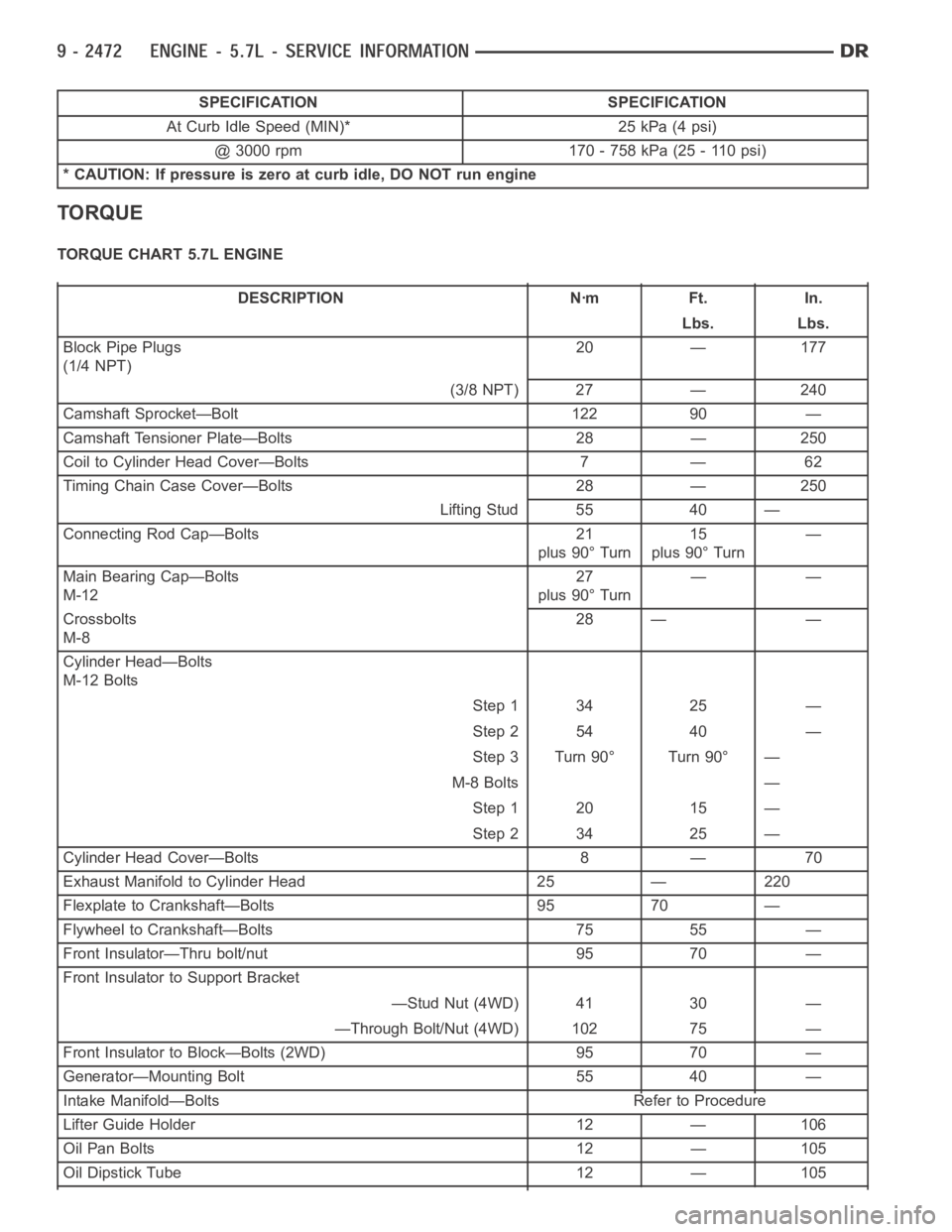
SPECIFICATION SPECIFICATION
At Curb Idle Speed (MIN)* 25 kPa (4 psi)
@ 3000 rpm 170 - 758 kPa (25 - 110 psi)
* CAUTION: If pressure is zero at curb idle, DO NOT run engine
TORQUE
TORQUE CHART 5.7L ENGINE
DESCRIPTION Nꞏm Ft. In.
Lbs. Lbs.
Block Pipe Plugs
(1/4 NPT)20 — 177
(3/8 NPT) 27 — 240
Camshaft Sprocket—Bolt 122 90 —
Camshaft Tensioner Plate—Bolts 28 — 250
Coil to Cylinder Head Cover—Bolts 7 — 62
Timing Chain Case Cover—Bolts 28 — 250
Lifting Stud 55 40 —
Connecting Rod Cap—Bolts 21
plus 90° Turn15
plus 90° Turn—
Main Bearing Cap—Bolts
M-1227
plus 90° Turn——
Crossbolts
M-828 — —
Cylinder Head—Bolts
M-12 Bolts
Step 1 34 25 —
Step 2 54 40 —
Step 3 Turn 90° Turn 90° —
M-8 Bolts —
Step 1 20 15 —
Step 2 34 25 —
Cylinder Head Cover—Bolts 8 — 70
Exhaust Manifold to Cylinder Head 25 — 220
Flexplate to Crankshaft—Bolts 95 70 —
Flywheel to Crankshaft—Bolts 75 55 —
Front Insulator—Thru bolt/nut 95 70 —
Front Insulator to Support Bracket
—Stud Nut (4WD) 41 30 —
—Through Bolt/Nut (4WD) 102 75 —
Front Insulator to Block—Bolts (2WD) 95 70 —
Generator—Mounting Bolt 55 40 —
Intake Manifold—Bolts Refer to Procedure
Lifter Guide Holder 12 — 106
Oil Pan Bolts 12 — 105
Oil Dipstick Tube 12 — 105
Page 1784 of 5267
SPECIAL TOOLS
5.7L ENGINE
BLOC-CHEK KIT C-3685
Bore Size Indicator C-119
Puller 8454
Crankshaft Damper Installer 8512
CRANKSHAFT DAMPER REMOVER INSERT - 8513-A
Dial Indicator C-3339
Handle C-4171
Page 1786 of 5267
ENGINE SUPPORT FIXTURE 8534
ENGINE LIFT FIXTURE 8984
VALVE SPRING COMPRESSOR - 9065
PUSHROD RETAINING PLATE - 9070
FRONT CRANK SEAL REMOVER - 9071
FRONT CRANK SEAL INSTALLER 9072
Page 1790 of 5267
CYLINDER HEAD
OPERATION—CYLINDER HEAD
The cylinder head closes the combustion chamber allowing the pistons to compress the air fuel mixture to the cor-
rect ratio for ignition. The valves located in the cylinder head open and close to either allow clean air into the com-
bustion chamber or to allow the exhaust gases out, depending on the stroke of the engine.
DIAGNOSIS AND TESTING—CYLINDER HEAD GASKET FAILURE
A cylinder head gasket leak can be located between adjacent cylinders or between a cylinder and the adjacent
water jacket.
Possible indications of the cylinder head gasket leaking between adjacent cylinders are:
− Loss of engine power
− Engine misfiring
− Poor fuel economy
Possible indications of the cylinder head gasket leaking between a cylinder and an adjacent water jacket are:
− Engine overheating
− Loss of coolant
− Excessive steam (white smoke) emitting from exhaust
− Coolant foaming
CYLINDER-TO-CYLINDER LEAKAGE TEST
To determine if an engine cylinder head gasket is leaking between adjacentcylinders, follow the procedures in Cyl-
inder Compression Pressure Test in this section. An engine cylinder head gasket leaking between adjacent cylinders
will result in approximately a 50–70% reduction in compression pressure.
CYLINDER-TO-WATER JACKET LEAKAGE TEST
WARNING: USE EXTREME CAUTION WHEN THE ENGINE IS OPERATING WITH COOLANT PRESSURE CAP
REMOVED.
VISUAL TEST METHOD
With the engine cool, remove the coolant pressure cap. Start the engine andallow it to warm up until thermostat
opens.
If a large combustion/compression pressure leak exists, bubbles will be visible in the coolant.
COOLING SYSTEM TESTER METHOD
WARNING: WITH COOLING SYSTEM TESTER IN PLACE, PRESSURE WILL BUILD UP FAST.EXCESSIVE
PRESSURE BUILT UP, BY CONTINUOUS ENGINE OPERATION, MUST BE RELEASED TO A SAFE PRESSURE
POINT. NEVER PERMIT PRESSURE TO EXCEED 138 kPa (20 psi).
Install Cooling System Tester 7700 or equivalent to pressure cap neck. Start the engine and observe the tester’s
pressure gauge. If gauge pulsates with every power stroke of a cylinder a combustion pressure leak is evident.
CHEMICAL TEST METHOD
Combustion leaks into the cooling system can also be checked by using Bloc-Chek Kit C-3685-A or equivalent.
Perform test following the procedures supplied with the tool kit.
Page 1792 of 5267
1. Perform the Fuel System Pressure Release proce-
dure (Refer to 14 - FUEL SYSTEM/FUEL DELIV-
ERY - STANDARD PROCEDURE). Disconnect the
fuelsupplyline(Referto14-FUELSYSTEM/
FUEL DELIVERY/QUICK CONNECT FITTING -
STANDARD PROCEDURE).
2. Disconnect the battery negative cable.
3. Drain cooling system (Refer to 7 - COOLING -
STANDARD PROCEDURE).
4. Remove the air cleaner resonator and duct work
(Refer to 9 - ENGINE/AIR INTAKE SYSTEM -
REMOVAL).
5. Remove closed crankcase ventilation system.
6. Disconnect the exhaust at the exhaust manifolds.
7. Disconnect the evaporation control system.
8. Disconnect heater hoses.
9. Remove the power steering pump.
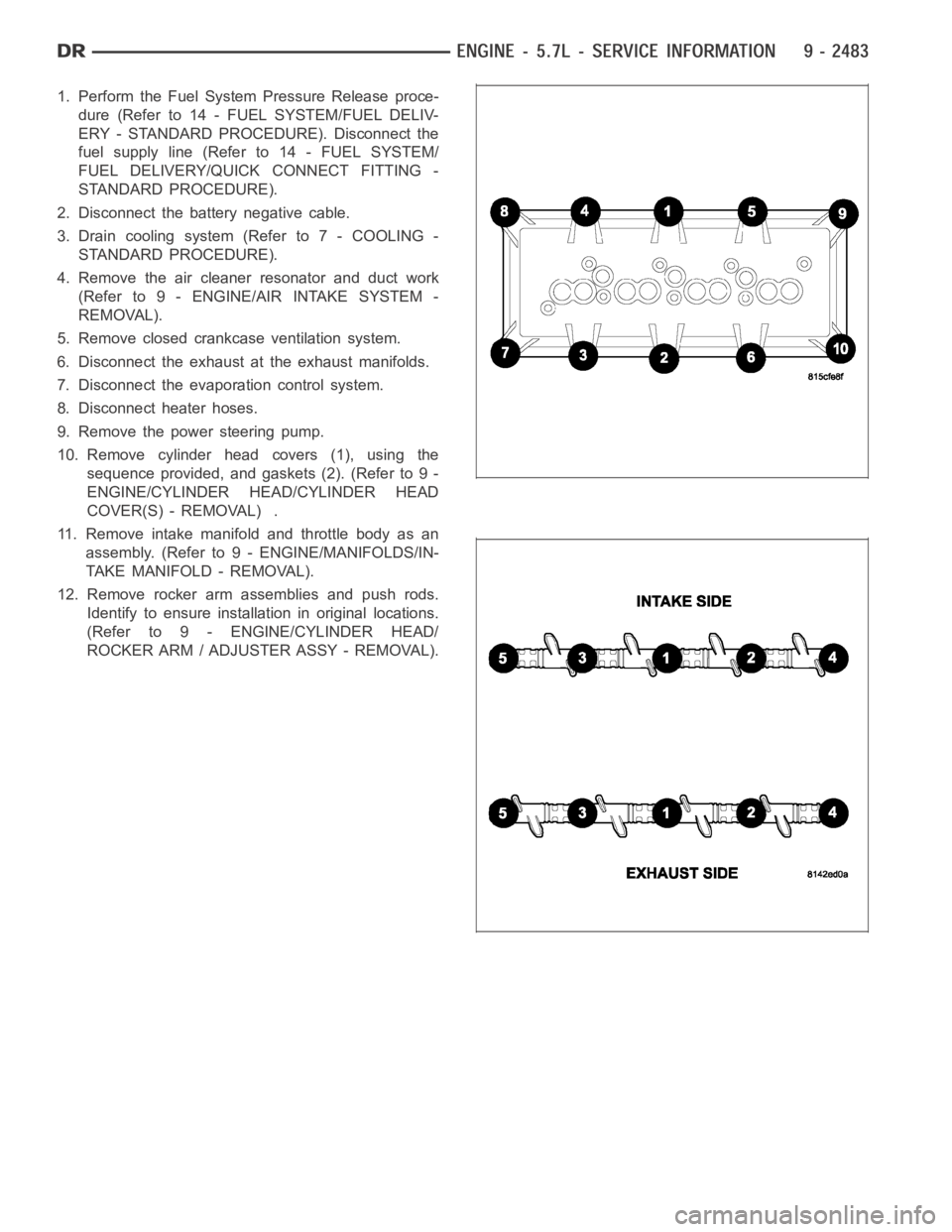
10. Remove cylinder head covers (1), using the
sequence provided, and gaskets (2). (Refer to 9 -
ENGINE/CYLINDER HEAD/CYLINDER HEAD
COVER(S) - REMOVAL) .
11. Remove intake manifold and throttle body as an
assembly. (Refer to 9 - ENGINE/MANIFOLDS/IN-
TAKE MANIFOLD - REMOVAL).
12. Remove rocker arm assemblies and push rods.
Identify to ensure installation in original locations.
(Refer to 9 - ENGINE/CYLINDER HEAD/
ROCKER ARM / ADJUSTER ASSY - REMOVAL).
Page 1796 of 5267
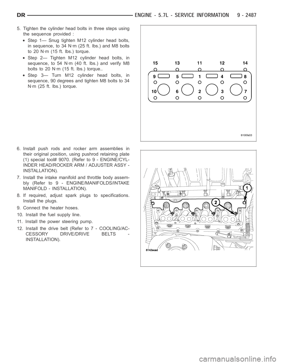
5. Tighten the cylinder head bolts in three steps using
the sequence provided :
Step 1— Snug tighten M12 cylinder head bolts,
in sequence, to 34 Nꞏm (25 ft. lbs.) and M8 bolts
to 20 Nꞏm (15 ft. lbs.) torque.
Step 2— Tighten M12 cylinder head bolts, in
sequence, to 54 Nꞏm (40 ft. lbs.) and verify M8
bolts to 20 Nꞏm (15 ft. lbs.) torque..
Step 3— Turn M12 cylinder head bolts, in
sequence, 90 degrees and tighten M8 bolts to 34
Nꞏm (25 ft. lbs.) torque.
6. Install push rods and rocker arm assemblies in
their original position, using pushrod retaining plate
(1) special tool# 9070. (Refer to 9 - ENGINE/CYL-
INDER HEAD/ROCKER ARM / ADJUSTER ASSY -
INSTALLATION).
7. Install the intake manifold and throttle body assem-
bly (Refer to 9 - ENGINE/MANIFOLDS/INTAKE
MANIFOLD - INSTALLATION).
8. If required, adjust spark plugs to specifications.
Install the plugs.
9. Connect the heater hoses.
10. Install the fuel supply line.
11. Install the power steering pump.
12. Install the drive belt (Refer to 7 - COOLING/AC-
CESSORY DRIVE/DRIVE BELTS -
INSTALLATION).
Page 1798 of 5267
13. Install cylinder head covers (1) (Refer to 9 -
ENGINE/CYLINDER HEAD/CYLINDER HEAD
COVER(S) - INSTALLATION).
14. Connect the evaporation control system.
15. Install the air cleaner (Refer to 9 - ENGINE/AIR
INTAKE SYSTEM - INSTALLATION).
16. Fill cooling system (Refer to 7 - COOLING -
STANDARD PROCEDURE).
17. Connect the negative cable to the battery.
18. Start engine check for leaks.