Page 5035 of 5267
B2214–(HVAC) CLIMATE CONTROL INTERNAL
For a complete wiring diagramRefer to Section 8W.
When Monitored:
With the ignition on.
Set Condition:
If the A/C Heater Control has an internal fault. This DTC has a maturing timeof 5 seconds and a de-maturing
time of 10 seconds. If the DTC’s status changes from active to stored it willstay in memory for 100 ignition
cycles.
Possible Causes
A/C HEATER CONTROL
NOTE: This DTC must be active for the results of this test to be valid. Do not perform this test if this DTC
is stored. Refer to either HVAC System Test (ATC) or to HVAC System Test (MTC) for stored DTC test pro-
cedures.
Diagnostic Test
1.REPLACE THE A/C HEATER CONTROL
Repair
Replace the A/C Heater Control in accordance with the Service Information.
Perform BODY VERIFICATION TEST – VER 1. (Refer to 8 - ELECTRICAL/ELECTRONIC CONTROL
MODULES - STANDARD PROCEDURE).
Page 5036 of 5267
U0019–CAN B BUS
For a complete wiring diagramRefer to Section 8W.
Page 5037 of 5267
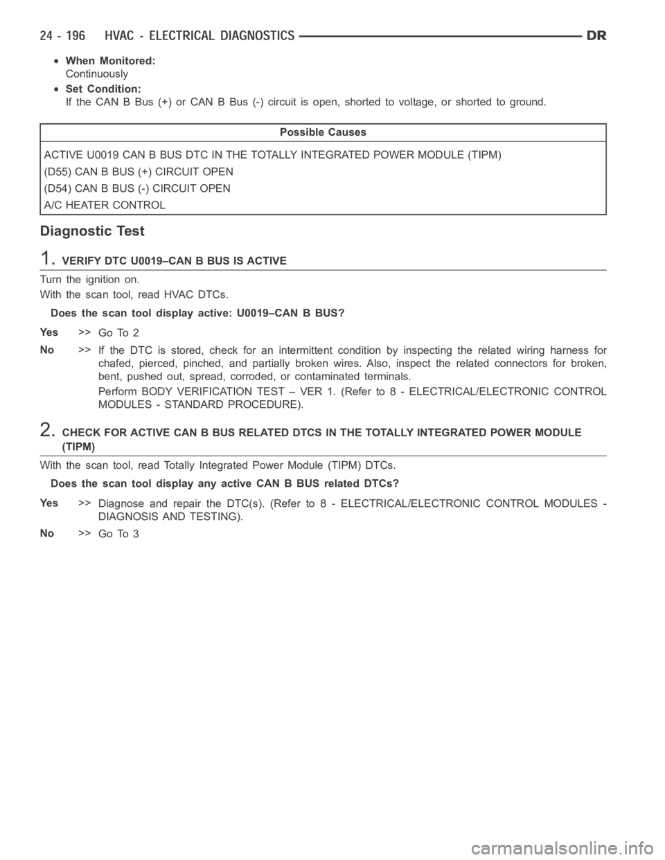
When Monitored:
Continuously
Set Condition:
If the CAN B Bus (+) or CAN B Bus (-) circuit is open, shorted to voltage, or shorted to ground.
Possible Causes
ACTIVE U0019 CAN B BUS DTC IN THE TOTALLY INTEGRATED POWER MODULE (TIPM)
(D55) CAN B BUS (+) CIRCUIT OPEN
(D54) CAN B BUS (-) CIRCUIT OPEN
A/C HEATER CONTROL
Diagnostic Test
1.VERIFY DTC U0019–CAN B BUS IS ACTIVE
Turn the ignition on.
With the scan tool, read HVAC DTCs.
Does the scan tool display active: U0019–CAN B BUS?
Ye s>>
Go To 2
No>>
If the DTC is stored, check for an intermittent condition by inspecting therelated wiring harness for
chafed, pierced, pinched, and partially broken wires. Also, inspect the related connectors for broken,
bent, pushed out, spread, corroded, or contaminated terminals.
Perform BODY VERIFICATION TEST – VER 1. (Refer to 8 - ELECTRICAL/ELECTRONIC CONTROL
MODULES - STANDARD PROCEDURE).
2.CHECK FOR ACTIVE CAN B BUS RELATED DTCS IN THE TOTALLY INTEGRATED POWER MODULE
(TIPM)
With the scan tool, read Totally Integrated Power Module (TIPM) DTCs.
Does the scan tool display any active CAN B BUS related DTCs?
Ye s>>
Diagnose and repair the DTC(s). (Refer to 8 - ELECTRICAL/ELECTRONIC CONTROL MODULES -
DIAGNOSIS AND TESTING).
No>>
Go To 3
Page 5038 of 5267
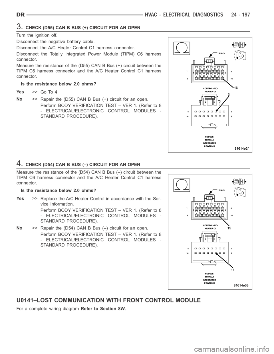
3.CHECK(D55)CANBBUS(+)CIRCUITFORANOPEN
Turn the ignition off.
Disconnect the negative battery cable.
Disconnect the A/C Heater Control C1 harness connector.
Disconnect the Totally Integrated Power Module (TIPM) C6 harness
connector.
Measure the resistance of the (D55) CAN B Bus (+) circuit between the
TIPM C6 harness connector and the A/C Heater Control C1 harness
connector.
Is the resistance below 2.0 ohms?
Ye s>>
Go To 4
No>>
Repair the (D55) CAN B Bus (+) circuit for an open.
Perform BODY VERIFICATION TEST – VER 1. (Refer to 8
- ELECTRICAL/ELECTRONIC CONTROL MODULES -
STANDARD PROCEDURE).
4.CHECK (D54) CAN B BUS (–) CIRCUIT FOR AN OPEN
Measure the resistance of the (D54) CAN B Bus (–) circuit between the
TIPM C6 harness connector and the A/C Heater Control C1 harness
connector.
Is the resistance below 2.0 ohms?
Ye s>>
Replace the A/C Heater Control in accordance with the Ser-
vice Information.
Perform BODY VERIFICATION TEST – VER 1. (Refer to 8
- ELECTRICAL/ELECTRONIC CONTROL MODULES -
STANDARD PROCEDURE).
No>>
Repair the (D54) CAN B Bus (–) circuit for an open.
Perform BODY VERIFICATION TEST – VER 1. (Refer to 8
- ELECTRICAL/ELECTRONIC CONTROL MODULES -
STANDARD PROCEDURE).
U0141–LOST COMMUNICATION WITH FRONT CONTROL MODULE
For a complete wiring diagramRefer to Section 8W.
Page 5039 of 5267
When Monitored:
With the ignition on.
Set Condition:
If the A/C Heater Control looses communication with the Totally Integrated Power Module (TIPM).
(Refer to 8 - ELECTRICAL/ELECTRONIC CONTROL MODULES - DIAGNOSIS AND TESTING)for the diagnostic
test procedure.
U0151–LOST COMMUNICATION WITHOCCUPANT RESTRAINT CONTROLLER
(ORC)
For a complete wiring diagramRefer to Section 8W.
When Monitored:
With the ignition on.
Set Condition:
If the A/C Heater Control looses communication with the Occupant Restraint Controller (ORC).
(Refer to 8 - ELECTRICAL/ELECTRONIC CONTROL MODULES - DIAGNOSIS AND TESTING)for the diagnostic
test procedure.
U0154–LOST COMMUNICATION WITH OCCUPANT CLASSIFICATION MODULE
For a complete wiring diagramRefer to Section 8W.
When Monitored:
With the ignition on.
Set Condition:
If the A/C Heater Control looses communication with the Occupant Classification Module (OCM).
(Refer to 8 - ELECTRICAL/ELECTRONIC CONTROL MODULES - DIAGNOSIS AND TESTING)for the diagnostic
test procedure.
U0155–LOST COMMUNICATION WITH CLUSTER/CCN
For a complete wiring diagramRefer to Section 8W.
When Monitored:
With the ignition on.
Set Condition:
If the A/C Heater Control looses communication with the Cluster (CCN).
(Refer to 8 - ELECTRICAL/ELECTRONIC CONTROL MODULES - DIAGNOSIS AND TESTING)for the diagnostic
test procedure.
U0156–LOST COMMUNICATION WITH EOM
For a complete wiring diagramRefer to Section 8W.
When Monitored:
With the ignition on.
Set Condition:
If the A/C Heater Control looses communication with the Compass Temperature Module (EOM).
(Refer to 8 - ELECTRICAL/ELECTRONIC CONTROL MODULES - DIAGNOSIS AND TESTING)for the diagnostic
test procedure.
U0168–LOST COMMUNICATION WITHVEHICLE SECURITY CONTROL MODULE
(SKREEM/WCM)
For a complete wiring diagramRefer to Section 8W.
Page 5040 of 5267
When Monitored:
With the ignition on.
Set Condition:
If the A/C Heater Control looses communication with the Vehicle Security Control Module (SKREEM/WCM).
(Refer to 8 - ELECTRICAL/ELECTRONIC CONTROL MODULES - DIAGNOSIS AND TESTING)for the diagnostic
test procedure.
U0169–LOST COMMUNICATION WITH SUNROOF CONTROL MODULE
For a complete wiring diagramRefer to Section 8W.
When Monitored:
With the ignition on.
Set Condition:
If the A/C Heater Control looses communication with the Sunroof Control Module (SCM).
(Refer to 8 - ELECTRICAL/ELECTRONIC CONTROL MODULES - DIAGNOSIS AND TESTING)for the diagnostic
test procedure.
U0184–LOST COMMUNICATION WITH RADIO
For a complete wiring diagramRefer to Section 8W.
When Monitored:
With the ignition on.
Set Condition:
If the A/C Heater Control looses communication with the Radio.
(Refer to 8 - ELECTRICAL/ELECTRONIC CONTROL MODULES - DIAGNOSIS AND TESTING)for the diagnostic
test procedure.
U0186–LOST COMMUNICATION WITH AUDIO AMPLIFIER
For a complete wiring diagramRefer to Section 8W.
When Monitored:
With the ignition on.
Set Condition:
If the A/C Heater Control looses communication with the Amplifier (AMP).
(Refer to 8 - ELECTRICAL/ELECTRONIC CONTROL MODULES - DIAGNOSIS AND TESTING)for the diagnostic
test procedure.
U0195–LOST COMMUNICATION WITH SDARS
For a complete wiring diagramRefer to Section 8W.
When Monitored:
With the ignition on.
Set Condition:
If the A/C Heater Control looses communication with the Satellite Audio Receiver (SDARS).
(Refer to 8 - ELECTRICAL/ELECTRONIC CONTROL MODULES - DIAGNOSIS AND TESTING)for the diagnostic
test procedure.
U0196–LOST COMMUNICATION WITHVEHICLE ENTERTAINMENT CONTROL
MODULE
For a complete wiring diagramRefer to Section 8W.
Page 5041 of 5267
When Monitored:
With the ignition on.
Set Condition:
If the A/C Heater Control looses communication with the Vehicle Entertainment System (VES).
(Refer to 8 - ELECTRICAL/ELECTRONIC CONTROL MODULES - DIAGNOSIS AND TESTING)for the diagnostic
test procedure.
U0197–LOST COMMUNICATION WITH HANDS FREE PHONE MODULE
For a complete wiring diagramRefer to Section 8W.
When Monitored:
With the ignition on.
Set Condition:
If the A/C Heater Control looses communication with the Hands Free Phone Module (HFM).
(Refer to 8 - ELECTRICAL/ELECTRONIC CONTROL MODULES - DIAGNOSIS AND TESTING)for the diagnostic
test procedure.
DTC SET DURING ROUTINE - TEST NOT PASSED
For a complete wiring diagramRefer to Section 8W.
When Monitored:
When the Cooldown Test is executed.
Set Condition:
If the A/C system is unable to lower the evaporator temperature 11.11°C (20°F) within one minute.
For dual-zone HVAC systems,refer to B10B2-A/C COOL DOWN TEST PERFORMANCEfor the diagnostic test
procedure. For single-zone HVAC systems,refer to B1079–CLIMATE CONTROL COOL DOWN TEST EXCESSIVE
TIMEfor the diagnostic test procedure.
BLOWERS NOT ON HIGH - TEST NOT RUN
For a complete wiring diagramRefer to Section 8W.
When Monitored:
When the Cooldown Test is executed.
Set Condition:
If either the blower speed was not set to high speed prior to starting the Cooldown Test or the blower speed
was changed from high speed to another setting after starting the Cooldowntest.
For dual-zone HVAC systems,refer to B10B2-A/C COOL DOWN TEST PERFORMANCEfor the diagnostic test
procedure. For single-zone HVAC systems,refer to B1079–CLIMATE CONTROL COOL DOWN TEST EXCESSIVE
TIMEfor the diagnostic test procedure.
REFRIGERANT TEMPERATURE SENSOR ERROR
For a complete wiring diagramRefer to Section 8W.
When Monitored:
When the Cooldown Test is executed.
Set Condition:
If a fault occurred with the Evaporator Temperature Sensor/sensor circuits.
For dual-zone HVAC systems,refer to B10B2-A/C COOL DOWN TEST PERFORMANCEfor the diagnostic test
procedure. For single-zone HVAC systems,refer to B1079–CLIMATE CONTROL COOL DOWN TEST EXCESSIVE
TIMEfor the diagnostic test procedure.
Page 5042 of 5267
*BLOWER MOTOR INOPERATIVE
For a complete wiring diagramRefer to Section 8W