Page 105 of 133

Reference
At a glance
Controls
Driving tips
Mobility
103
Liftgate lamp
5 Watt bulb
1.Take out the bulb holder.
2.Replace the bulb.
Wheel changes
Safety precautions to observe in the
event of a flat tire and during all tire
changes:
Park the vehicle as far as possible from passing
traffic. Park on a firm, flat, surface. Switch on the
hazard warning flashers.
Lock the steering wheel with the wheels point-
ing straight ahead. Engage the handbrake and
shift into first gear or reverse, or move the
selector lever to position P.
All passengers should be outside the vehicle
and well away from your immediate working
area, behind a guardrail, for instance.
If a warning triangle or portable hazard warning
lamp is required, set it up on the roadside at an
appropriate distance from the rear of the vehi-
cle. Comply with all safety guidelines and regu-
lations.
Change the wheel only on a level, firm surface
which is not slippery. The vehicle or the jack
could slip to the side if you attempt to raise the
vehicle on a soft or slippery surface such as
snow, ice, tile, etc.
Position the jack on a firm support surface.
Do not use a wooden block or similar object as a
support base for the jack, as this would prevent
it from extending to its full support height and
reduce its load-carrying capacity.To avoid serious or fatal injury: never lie under
the vehicle, and never start the engine while it is
supported by the jack.<
What you will need
Open liftgate and raise or remove floor cover,
refer to page72.
1Vehicle jack
2Lug wrench
3Chocks, folding
In order to avoid rattling noises later, note the
position of the tools when you remove them and
return them to their original position when you
are through using them.
Compact wheel
The compact wheel is located under the cargo
area on the undercarriage of the vehicle.
Removing compact wheel
1.Unscrew bolt, refer to arrow1.
2.Fold up lifting handle, refer to arrow2.
Page 106 of 133

Replacing components
104 3.Turn the handle to the left as far as possible,
refer to arrow3.
Turning the handle releases the com-
pact wheel. Its weight of approx.
18 lbs./8 kg is then entirely supported by
the handle.<
4.Slowly lower the handle as far as possible,
refer to arrow4.
5.Pull the compact wheel to the rear so that it
is still securely resting in its compact wheel
receptacle.
6.If need be, turn the wheel in the compact
wheel receptacle so that the attachment of
the retaining strap to the rim points toward
the rear.
7.Rotate the clamp by 180°, refer to arrows 1,
and unhook the retaining strap from the
clamp, refer to arrow 2.
8.Take out the compact wheel toward the
back.
9.Fasten the retaining strap to the compact
wheel receptacle and resecure the compact
wheel receptacle by reversing the above
steps.
The width of the defective wheel prevents
it from fitting into the compact wheel receptacle in place of the compact wheel
itself.<
Inserting compact wheel
The compact wheel is reinserted in the reverse
sequence of its removal.
When attaching the retaining strap to the
compact wheel, make sure the belt is
threaded through 2 rim openings, with one
unoccupied hole between them; otherwise, the
compact wheel could come loose in an acci-
dent.<
Preparing wheel change
1.Observe the safety precautions on
page103.
2.Secure the vehicle to prevent it from rolling:
place the wheel chock behind the front
wheel on the side of the vehicle opposite
the side being raised. If the vehicle is parked
on a downward slope, place the wheel
chock securely in front of the tire. If the
wheel must be changed on a surface with
a more severe slope, take additional pre-
cautions to secure the vehicle from rolling.
3.Loosen the lug bolts by a γ turn.
Jacking up vehicle
1.Position the vehicle jack at the jacking point
closest to the wheel so that the entire sur-
face of the jack base perpendicularly con-
tacts the ground under the jacking point.
The vehicle jack is designed for
changing wheels only. Do not attempt
to raise another vehicle model with it or to
raise any load of any kind. To do so could
cause accidents and personal injury.<
Page 107 of 133

Reference
At a glance
Controls
Driving tips
Mobility
105
2.Guide the jack head into the rectangular
recess of the jacking point when cranking
up, refer to drawing inset.
3.Jack the vehicle up until the wheel you are
changing is raised from the ground.
Mounting a wheel
1.Unscrew the lug bolts and remove the
wheel.
2.Remove accumulations of mud or dirt from
the mounting surfaces of the wheel and
hub. Clean the lug bolts.
3.Position the new wheel or compact wheel.
Secure the wheel by screwing at least two
lug bolts into opposite bolt holes. When you
mount wheels other than Genuine BMW
light-alloy wheels, different lug bolts may
also be required.
4.Screw in the remaining lug bolts. Tighten all
the bolts securely in a diagonal pattern.
5.Lower the jack and remove it from beneath
the vehicle.
After mounting
1.Tighten the lug bolts in a diagonal pattern.
To ensure safety, always have the lug
bolts checked with a calibrated
torque wrench as soon as possible to
ensure that they are tightened to the speci-
fied torque. The tightening torque is
101lbft/140Nm.<
2.Stow the defective wheel in the cargo area.
3.Check and correct the tire inflation pressure
at the earliest opportunity.
Protect valve stems and valve stem
seal caps from dirt and contamina-tion. Dirt in valve stems is a frequent source
of gradual air loss.<
4.Reinitialize the Flat Tire Monitor
* or reset
the Tire Pressure Monitor
*, refer to
pages51, 52.
Do not initialize the Flat Tire Monitor
when driving with a compact wheel.<
5.Replace the damaged tire with a new one as
soon as possible and have the new wheel
balanced.
Driving with compact wheel
Drive reservedly and do not exceed a
speed of 50 mph/80 km/h. Do not deacti-
vate DSC; otherwise, unstable driving condi-
tions may result.<
Mounting the compact wheel can change the
driving characteristics. For example, it can
reduce tracking stability during braking, extend
braking distances, and alter self-steering char-
acteristics in the limit range. With winter tires,
these characteristics are more pronounced.
Only one compact wheel may be
mounted. You should re-equip with
wheels and tires of the original size as quickly as
possible.<
Vehicle battery
Maintenance
The battery is 100 % maintenance-free, i.e., the
electrolyte will last for the life of the battery
when the vehicle is operated in a temperate cli-
mate. Your BMW Sports Activity Vehicle Center
will be happy to advise you on all questions con-
cerning the battery.
Warning lamp
The warning lamp lights up. The battery
is no longer being charged. The alterna-
tor V-belt is defective or there is a mal-
function in the charge current circuit of the
alternator. Have the system checked immedi-
ately.
Page 108 of 133

Replacing components
106 Do not continue driving if the V-belt is
defective. The engine could be damaged
due to overheating.
Moreover, an increased amount of force is
required for steering if there is a sharp drop in
the onboard supply voltage.<
Charging battery
Charge the battery in the vehicle only when the
engine has been switched off. For connections,
refer to Jump starting on page108.
Disposal
Have old batteries disposed of following
replacement at your BMW Sports Activity
Vehicle Center or bring them to a collection
point. Maintain the battery in an upright position
for transport and storage. Always secure the
battery to prevent it from tipping over during
transport.<
Power failure
After a temporary power supply interruption,
some equipment is subject to limited use and
must be reinitialized. Individual settings are also
lost and must be updated again:
>Panorama glass sunroof
It may be only possible to raise the sunroof.
The system must be initialized, refer to
page23.
>Power windows
The pinch protection system must be reini-
tialized, refer to page22.
>Seat and mirror memory
The positions must be stored again, refer to
page29.
>Time
Must be set again, refer to page44.
Fuses
Never attempt to repair a blown fuse, and
do not replace a defective fuse with a sub-
stitute of another color or amperage rating, as
this could lead to a circuit overload, ultimately
resulting in a fire in the vehicle.<
Open the glove compartment and turn the two
quick-release fasteners to the left, refer to
arrows.
Spare fuses, plastic tweezers, and information
about fuse allocation are stored with the fuses.
Page 109 of 133

Reference
At a glance
Controls
Driving tips
Mobility
107
Giving and receiving assistance
Receiving assistance
The Roadside Assistance of the BMW Group
offers you assistance in the event of a break-
down around the clock, as well as on weekends
and public holidays.
The phone numbers of the Roadside Assis-
tance control center in your home country can
be found in the BMW Dealer directory.
In the case of vehicles with the corresponding
equipment, you can use buttons in the head-
liner to contact Roadside Assistance or initiate
an emergency call.
When the emergency call is initiated, a tele-
phone connection is established to the BMW
Assist response center.
In vehicles with BMW Assist enabled, if the cur-
r en t p o s it io n o f y o u r v eh i c le c a n b e d et e r m in e d ,
it will be transmitted to the BMW Assist
response center.
The conditions for initiating an emergency call
or contacting Roadside Assistance:
>Ignition key in position 1 or higher
>The car phone is logged on to a mobile tele-
phone network
>The emergency call system is operable
Access to buttons*
To open the cover:
Briefly press the cover, refer to arrow.
1Emergency call
2Roadside Assistance
Initiating an emergency call*
Press button 1 for at least 2 seconds.
The LED above the button lights up. As soon as
a voice connection to the BMW Assist response
center has been established, the LED flashes. If
the LED flashes, but you are unable to hear the
emergency response center, you can still be
heard by the response center.
For technical reasons, the emergency call
cannot be guaranteed under the most
unfavorable conditions.<
Under certain conditions, an emergency call is
initiated automatically immediately after a
severe accident. The automatic emergency call
is not affected by the button being pressed.
Roadside Assistance*
Press button 2 for at least 2 seconds.
The LED above the button lights up. As soon as
a voice connection to Roadside Assistance has
been established, the LED flashes.
On a country-specific basis, with BMW Assist
enabled, the current position of your vehicle is
determined at the same time.
Warning triangle*
The warning triangle is stored behind the right
side panel in the cargo area.
To open the side trim panel: press the button.
Page 110 of 133

Giving and receiving assistance
108
First-aid kit*
Beneath the front passenger's seat.
To open: pull the handle and fold the cover
downward.
To close: fold the cover up.
Some of the articles in the first-aid kit may be
used within a limited time only. Check the expi-
ration dates of the contents regularly and
replace the contents in a timely fashion as
needed.
Jump starting
When your battery is discharged, you can use
two jumper cables to start the engine of your
BMW with power from the battery in another
vehicle. You can also use the same method to
help start another vehicle. Use only jumper
cables with fully-insulated clamp handles.
To avoid the risk of potentially fatal injury,
always avoid all contact with electrical
components while the engine is running. Care-
fully observe the following instructions to avoid
personal injury and/or damage to one or both
vehicles.<
Preparing
1.Check whether the battery of the other
vehicle has a voltage of 12 Volts and
approximately the same capacitance in Ah.
This information can be found on the bat-
tery.
2.Switch off the engine of the vehicle provid-
ing assistance.
3.Switch off any electrical systems and com-
ponents in both vehicles.Ensure that no contact exists between
the bodywork on the two vehicles; other-
wise, there is a danger of short circuits.<
Connecting jumper cables
Connect the jumper cables in the correct
order; failure to do so could generate
sparks and cause injury.<
In your BMW, the so-called jump starting termi-
nal in the engine compartment functions as the
positive battery terminal, also refer to Engine
compartment overview on page93. The sym-
bol + is embossed on the cover.
1.Open the cover of the BMW jump starting
terminal, refer to arrow1.
2.Connect one terminal clamp of the posi-
tive/+ jumper cable to the positive terminal
of the battery or to a jump starting terminal
of the vehicle providing starting assistance.
3.Connect the second terminal clamp of the
positive/+ jumper cable to the positive ter-
minal of the battery or to a jump starting ter-
minal of the vehicle to be started.
Your BMW has a special nut that serves as the
body ground or negative terminal, refer to
arrow2.
4.Connect one terminal clamp of the nega-
tive/– jumper cable to the negative terminal
of the battery or to an engine or body
ground of the vehicle providing assistance.
5.Connect the second terminal clamp of the
negative/– jumper cable to the negative ter-
minal of the battery or to the engine or body
ground of the vehicle to be started.
Page 111 of 133

Reference
At a glance
Controls
Driving tips
Mobility
109
Starting engine
1.Start the engine of the assisting vehicle and
let it run at a slightly elevated idling speed
for a few minutes.
2.Start the engine on the other vehicle in the
usual way.
If the first start attempt is not successful,
wait a few minutes before another attempt
in order to allow the discharged battery to
recharge.
3.Let the engines run for a few minutes.
4.Disconnect the jumper cables by reversing
the connection sequence.
If need be, have the battery checked and
recharged.
Never use spray fluids to start the
engine.<
Tow starting and towing
Obey all applicable laws and guidelines
for tow starting and towing.<
Do not allow any passengers other than
the driver to ride in a vehicle that is being
towed.<
Using tow fitting
The threaded tow fitting is stored in the
onboard tool kit, refer to page99, and must
always remain in the vehicle. It can be screwed
in at the front or rear of the BMW.
Only use the tow fitting that comes with
the vehicle and screw it in as far as it will
go. Use the tow fitting only for towing on roads.
Avoid lateral loading of the tow fitting, e.g. do
not lift the vehicle by the tow fitting. Otherwise,
the tow fitting and the vehicle can be dam-
aged.<
Access to screw thread
Press out the cover in the front or rear bumper
at the notch at the bottom with a screwdriver.
Being towed
Make sure that the ignition key is in posi-
tion 1; otherwise, the steering lock will
engage, making it impossible to steer the vehi-
cle. There is no power assist with the engine
switched off. It is therefore necessary to exert
increased effort for braking and steering.<
Switch on the hazard warning flashers depend-
ing on the local regulations. If the electrical sys-
tem fails, mark the vehicle to be towed, e.g. with
a sign or warning triangle in the rear window.
Do not exceed a towing speed of
30 mph/50 km/h and a towing distance of
95 miles/150 km; otherwise, the drive train may
be damaged.<
Manual transmission
Gearshift lever in neutral.
Automatic transmission
Selector lever in position N.
Changing selector lever positions, refer to
page38.
Towing methods
In some countries, towing with tow bars or
ropes on public roads is not permitted.
Familiarize yourself with the regulations on tow-
ing in the specific country.
Page 112 of 133

Giving and receiving assistance
110
With tow bar
The towing vehicle must not be lighter
than the vehicle to be towed; otherwise,
it will not be possible to safely control vehicle
response.<
The tow fittings used should be on the same
side on both vehicles. Should it prove impossi-
ble to avoid mounting the tow bar at an offset
angle, please observe the following:
>Clearance and maneuvering capability will
be strictly limited in corners.
>When mounted at an angle, the tow bar will
exert lateral forces, tending to push the
vehicle sideways.
Secure the tow bar to the tow fittings
only. Otherwise, other vehicle parts could
be damaged.<
With tow-rope
When starting off in the towing vehicle, make
sure that the tow-rope is taut.
To avoid jerking and the associated
stresses on vehicle components when
towing, always use nylon ropes or nylon straps.
Secure the tow rope to the tow fittings only.
Otherwise, other vehicle parts could be dam-
aged.<
With tow truck
Do not tow the X3 with only the front or
rear axle raised; otherwise, the wheels
could lock and the transfer case could be dam-
aged.<
Have the X3 transported only on a flat bed.To avoid damage, do not lift the vehicle
from the tow fitting or body and suspen-
sion parts.<
Tow starting
If possible, do not tow start the vehicle; jump
start the engine instead, refer to page108.
Vehicles equipped with catalytic convertors
should only be tow started when the engine is
cold. It is not possible to tow start an engine
equipped with an automatic transmission.
1.Switch on hazard warning flashers, comply
with local regulations.
2.Switch on ignition, refer to page36.
3.Shift into 3rd gear.
4.Have the vehicle tow-started with the clutch
depressed and slowly release the clutch.
After the engine starts, immediately
depress the clutch again.
5.Stop at a suitable location, remove the tow
bar or rope and switch off the hazard warn-
ing flashers.
6.Have the vehicle checked.
Do not activate the HDC Hill Descent
Control during tow starting, refer to
page49.<
 1
1 2
2 3
3 4
4 5
5 6
6 7
7 8
8 9
9 10
10 11
11 12
12 13
13 14
14 15
15 16
16 17
17 18
18 19
19 20
20 21
21 22
22 23
23 24
24 25
25 26
26 27
27 28
28 29
29 30
30 31
31 32
32 33
33 34
34 35
35 36
36 37
37 38
38 39
39 40
40 41
41 42
42 43
43 44
44 45
45 46
46 47
47 48
48 49
49 50
50 51
51 52
52 53
53 54
54 55
55 56
56 57
57 58
58 59
59 60
60 61
61 62
62 63
63 64
64 65
65 66
66 67
67 68
68 69
69 70
70 71
71 72
72 73
73 74
74 75
75 76
76 77
77 78
78 79
79 80
80 81
81 82
82 83
83 84
84 85
85 86
86 87
87 88
88 89
89 90
90 91
91 92
92 93
93 94
94 95
95 96
96 97
97 98
98 99
99 100
100 101
101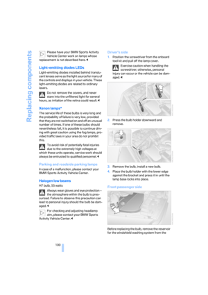 102
102 103
103 104
104 105
105 106
106 107
107 108
108 109
109 110
110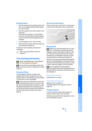 111
111 112
112 113
113 114
114 115
115 116
116 117
117 118
118 119
119 120
120 121
121 122
122 123
123 124
124 125
125 126
126 127
127 128
128 129
129 130
130 131
131 132
132