Page 1900 of 2893
 System Operation
21-21
99
(1)
140
196
(2)
28 3,138
(32)
455 kPa
(kgf/cm )
psi
V
4.575")
����
�µ�µ
�¦�µ �§ �¦ �§ �¦�§
�¦�§
A/C Pressure Sensor
A/C System Pressure Sensor Output
Voltage (V out) System Operation
21-21
99
(1)
140
196
(2)
28 3,138
(32)
455 kPa
(kgf/cm )
psi
V
4.575
0.684
0.425
0.2945
OUTPUT
VOLTAGE
(Vout)
Vcc 5 V Vout GND
A/C PRESSURE2
The A/C pressure sensor converts A/C pressure into electrical signals to the ECM/PCM.
Abnormally low pressure: Below 196 kPa
(2.0 kgf/cm , 28 psi)
Below 0.685 V The ECM/PCM disengages the compressor
clutch. The radiator and condenser fans
operate based on engine coolant temperature.
Normal operating pressure: Above 196 kPa (2.0 kgf/cm , 28 psi)
Below 1,470 kPa (15.0 kgf/cm , 213 psi) 0.686 V to 1.944 V The ECM/PCM cycles the compressor clutch
based on cooling demand. The radiator and
condenser fans operate at low speed unless
the engine coolant temperature exceeds 206 °F.
High operating pressure: Above 1,470 kPa (15.0 kgf/cm , 213 psi)
Below 3,138 kPa (32 kgf/cm , 455 psi) 1.945 V to 4.575 V The ECM/PCM cycles the compressor clutch
based on cooling demand. The radiator and
condenser fans operate at high speed.
Abnormally high pressure: More than
3,138 kPa (32 kgf/cm , 455 psi) Above 4.575 V The ECM/PCM disengages the compressor
clutch. The radiator and condenser fans
operate based on engine coolant temperature.
: The A/C system pressure can be monitored in the HDS PGM-FI Data List.
The response of the A/C pressure sensor is shown in the graph.
(cont’d)
222
2
2
2
08/08/21 14:41:00 61SNR030_210_0022
ProCarManuals.com
DYNOMITE -2009-
Page 1905 of 2893
����
21-26Climate Control
Circuit Diagram
PNK
RED/BLK
12
1 2
Q6
1 2
GRN/REDRED
IG2 HOT in ON (II)
CAN HI
CAN LO
FAN HI ACC L
FAN LO A14
A4
A5 13
A/C C")
�����(�#�'�����������
���������������������������)����
21-26Climate Control
Circuit Diagram
PNK
RED/BLK
12
1 2
Q6
1 2
GRN/REDRED
IG2 HOT in ON (II)
CAN HI
CAN LO
FAN HI ACC L
FAN LO A14
A4
A5 13
A/C COMPRESSOR
2
RED/WHT
BLU
F26 MICU
1
19
21
A37
A36
BLK
A9 A33 A16 A19 PNK
WHT RED
1
23
RED
LT GRN
5V
BLK
VCC6
ACPD
TW2 GRN12
SG BLK
No. 15
(7.5 A)
(20 A) No. 6 A/C DIODE A
GRY RED
WHT
LT GRN
BRN
42 3 5
1 IG2
BAT
ORNNo. 36 (10 A)
BRN
BLK RED
BLU
2
1
G301 ECM/PCM
BATTERY
No. 1 (BAT) (100 A)
24
2
3
PUR
13
41 No. 9 (40 A)
No. 2 (IG) (50 A)
1
3
42
WHT
BLK
G301
No.20(7.5A)
1
3
2
4
PUR
UNDER-HOOD FUSE/RELAY BOX IGNITION SWITCH
UNDER-DASH
FUSE/RELAY BOX
RADIATOR
FAN RELAY
FAN CONTROL
RELAY
A/C
CONDENSER
FAN RELAY A/C
COMPRESSOR
CLUTCH RELAY
BLOWER
MOTOR
RELAY
RADIATOR
FAN
MOTOR
PGM-FI
SUB
RELAY
A/C
CONDENSER
FAN
MOTOR
ENGINE
COOLANT
TEMPERATURE
(ECT) SENSOR 2A/C PRESSURE
SENSOR
GAUGE
CONTROL
MODULE
(TACH)
A/C
COMPRESSOR
CLUTCH
UNDER-DASH
FUSE/RELAY
BOX
THERMAL
PROTECTOR
A/C
DIODE B
H1 C3 Q16
G12
D1
F11 F14 F12 F2 F7 F20 E8 F1 J2 No. 7 (20 A)
08/08/21 14:41:03 61SNR030_210_0027
ProCarManuals.com
DYNOMITE -2009-
Page 1941 of 2893
����
�µ
�µ
�µ
�µ �µ
�µ
�µ
�µ
YES
NO
YES
NO YES
NO
YES
NO
21-62
Climate Control
A/C Compressor Clutch Circuit Troubleshooting
A/C")
�µ�µ�µ�µ
���
�(�#�'�����������
���
�
���
�
�����
���������)����
�µ
�µ
�µ
�µ �µ
�µ
�µ
�µ
YES
NO
YES
NO YES
NO
YES
NO
21-62
Climate Control
A/C Compressor Clutch Circuit Troubleshooting
A/C COMPRESSOR CLUTCH RELAY 4P SOCKET
NOTE:
It is normal for the A/C compressor to turn off under certain conditions, such as low idle, high engine
coolant temperature, or hard acceleration.
Do not use this troubleshooting procedure if the fans are also inoperative with the A/C on. Refer to the
symptom troubleshooting index.
Before doing any symptom troubleshooting, check for powertrain DTCs (see page 11-3).
1. Check the No. 20 (7.5 A) fuse in the under-hood fuse/relay box, and the No. 36 (10 A) fuse in the
under-dash fuse/relay box.
Go to step 2.
Replace the fuses and recheck. If the fuses
blow again, check for a short in the No. 20 (7.5 A)
and No. 36 (10 A) fuses circuit.
2. Connect the HDS to the DLC.
3. Start the engine.
4. Turn on the A/C.
5. Using the HDS, confirm the following values in the PGM-FI Data List at idle.
ECT Sensor 2 80 100 °C (176 212 °F)
TP Sensor About 0.5 V at idle
RPM More than 670
A/C Switch ON
A/C Clutch ON
A/C Pressure
Sensor 196 455 kPa (28 455 psi)
Go to step 6.
Troubleshoot the value that is not within the
specifications. 6. Turn the ignition switch to LOCK (0).
7. Remove the A/C compressor clutch relay from the
under-hood fuse/relay box, and test it (see page
22-70).
Go to step 8.
Replace the A/C compressor clutch relay.
8. Measure the voltage between the A/C compressor clutch relay 4P socket terminal No. 1 and body
ground.
Go to step 9.
Replace the under-hood fuse/relay box
(see page 22-65).
Ar e t he f uses OK ?
Are all the values within specif ications? Is the relay OK ?
Is there battery voltage?
08/08/21 14:43:32 61SNR030_210_0063
ProCarManuals.com
DYNOMITE -2009-
Page 2189 of 2893
�����
�����
22-239
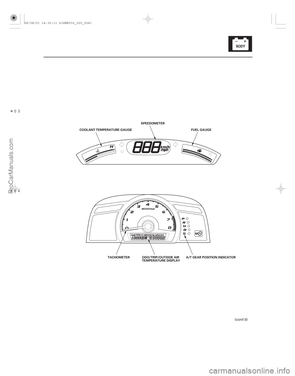
COOLANT TEMPERATURE GAUGESPEEDOMETER
FUEL GAUGE
TACHOMETER ODO/TRIP/OUTSIDE AIR
TEMPERATURE DISPLAY A/T GEAR POSITION INDICATOR
(cont’d)
08/08/21 14:35:11 61SNR030_220_0241
ProCarManuals.com
DYNOMITE -2009-
Page 2191 of 2893
����
Entering the self-diagnostic function with the HDS
Entering the self-diagnostic function (manual method)
22-241
Self-diagnostic Function
ON (I")
����
�(�#�'���������������
�����������������������)����
Entering the self-diagnostic function with the HDS
Entering the self-diagnostic function (manual method)
22-241
Self-diagnostic Function
ON (II)
OFF ON
OFF ON
Ignition
Switch
Lighting
Switch
SEL/RESET
Switch
5sec.
5sec.
LOCK (0)
Before troubleshooting the gauge system, refer to multiplex integrated control system B-CAN System Diagnosis Test
Mode A (see page 22-93).
The gauge control module (tach) has a self-diagnostic function shown, and also has a customizable reset function.
The beeper drive circuit check.
The indicator drive circuit check.
The switch input test.
The LCD segments check.
The gauges drive circuit check (Tachometer, Fuel gauge, Coolant temperature gauge).
The communication line check (B-CAN, F-CAN, and UART lines).
NOTE: Indicators are also controlled via the communication line.
Using the HDS, select Body Electrical, Gauges, then Function Test and do the self-diagnostic function.
Before doing the self-diagnostic function, check the No. 10 (7.5 A) fuse in the under-dash fuse/relay box and the No. 23
(10 A) fuse in the under-hood fuse/relay box. 1. Push and hold the SEL/RESET switch button.
2. Turn the headlights ON.
3. Turn the ignition switch to ON (II).
4. Within 5 sec., turn the headlights OFF, then ON and OFF again.
5. Within 5 sec., release the SEL/RESET switch button, and then push and release the button three times repeatedly.
NOTE: While in the self-diagnostic mode, the dash lights brightness controller operates normally.
While in the self-diagnostic mode, the SEL/RESET switch button is used to start the Beeper Drive Circuit Test and the Gauge Drive Circuit Check.
If the vehicle speed exceeds 2 km/h (1.2 mph) or the ignition switch is turned to LOCK (0), the self-diagnostic mode ends.
(cont’d)
Move to self-diagnostic mode.
08/08/21 14:35:11 61SNR030_220_0243
ProCarManuals.com
DYNOMITE -2009-
Page 2229 of 2893
����
Description
Outside Air Temperature Indicator Logic Update to the outside air temperature
indicator while driving
Troubleshooting
22-279
Ou")
�µ�µ�µ
�(�#�'���������������������
���������
�������)����
Description
Outside Air Temperature Indicator Logic Update to the outside air temperature
indicator while driving
Troubleshooting
22-279
Outside Air Temperature Indicator Calibration
The outside temperature sensor is located behind the
center of the front bumper. The gauge control module
(tach) uses measurements from this sensor to display
the outside air temperature.
Because of the location of the sensor, it may be affected
by heat reflection from the road, engine and radiator
heat or hot exhaust from surrounding traffic.
These conditions can heat soak the outside air
temperature sensor and cause inaccurate readings.
Logic has been written into the gauge control module
(tach) to help prevent abnormal or fluctuating outside
air temperature indicator readings.
Initial outside air temperature indication after the
ignition switch is turned to ON (II).
If the engine coolant temperature is 60 °C (140 °F) or higher when the ignition switch is turned to ON (II),
the outside air temperature indicated the last time the
key was turned off will be displayed regardless of the
current temperature measured by the outside air
temperature sensor.
If the engine coolant temperature is 59 °C (139 °F) or lower when the ignition switch is turned to ON (II), the
current temperature measured by the outside air
temperature sensor will be indicated. If the temperature measured by the outside air
temperature sensor is greater than the temperature on
the outside air temperature indicator, the outside air
temperature indicator will increase by 1 °C (1.8 °F) per
minute after the vehicle speed is greater than 30 km/h
(19 mph) for more than 1 minute and 30 seconds. It will
continue to increase until the current outside air
temperature is indicated. So, the first change to the
outside air temperature indicator is 1 minute and
30 seconds after the vehicle speed is greater than
30 km/h (19 mph). If the vehicle speed drops below
30 km/h (19 mph), the indicator will not update again
until the vehicle speed is increased to 30 km/h (19 mph)
or more for more than 1 minute and 30 seconds again.
If the outside air temperature is less than the indicated
temperature, the temperature will decrease 1 °C every
2 seconds (1 °F
every 1.1 seconds) until the current
outside air temperature is indicated regardless of
vehicle speed.
If the indicator displays ‘‘ ’’ for more than 2
seconds after selecting the outside air temperature
display mode, check the outside air temperature sensor
(see page 21-68), or gauge control module self-
diagnosis (see page 22-241).
(cont’d)
08/08/21 14:36:00 61SNR030_220_0281
ProCarManuals.com
DYNOMITE -2009-