Page 2723 of 2893
����
�µ
�´�µ �´
�´�µ
�µ
�´
24-43
WHT*
GRN* BLU* RED* RED*
GRY*
PUR*
LT GRN*
YEL*
BRN*
20
19
17 18
2
112
2P 2P
23
27 28
B 1
41 2
4P 2P
2
1
23 24
B SRS UNIT RIGHT SIDE
CURTAIN AIRBAG
INFLATOR
RIGHT SIDE
IMPACT
SENSOR
(SECOND)
RIGHT SIDE
IMPACT SENSOR (FIRST)
FRONT
PASSENGER’S
SIDE AIRBAG
INFLATOR
DRIVER’S
SIDE AIRBAG
INFLATOR FLOOR
WIRE
HARNESS
FLOOR
WIRE
HARNESS 2P BLU or BRN wire color
can be used for the SRS circuits
that have a * mark
LSA
LSA RSA RSA
RBS1 RBS1
RCA1
RCA1
08/08/21 13:55:37 61SNR030_240_0043
ProCarManuals.com
DYNOMITE -2009-
Page 2724 of 2893
���� ’07-09 models
24-44SRS
Circuit Diagram (cont’d)
GRN
BLU YEL
124 Q
E
G504
G602
BLK
LT GRN*
BLK*
BLK*
ORN*
LT BLU*
WHT*
RED* BLU*RED*
YEL*
2")
�Î�����(�#�'���������������������������������������)���� ’07-09 models
24-44SRS
Circuit Diagram (cont’d)
GRN
BLU YEL
124 Q
E
G504
G602
BLK
LT GRN*
BLK*
BLK*
ORN*
LT BLU*
WHT*
RED* BLU*RED*
YEL*
2 1
G506 5
22
23 13 BLU
MICURED
2
4 MICU
GRY
YEL
3
1
17 Vs
Vo
Vs
Vo
Vs
Vo
Vs
Vo BLU
BRN
5
10 15
GRY
123 3
21
LT GRN
16
11 6
GRY
BLU
GRN RED
4
914
WHT
123
321
BLK
13
83
RED
BRN MAIN CIRCUIT
VB
VA
WHT
GAUGE CONTROL MODULE (TACH)
BLK
412 SRS UNIT
ODS UNIT
7112 No. 9
(7.5 A) (7.5 A)
No. 10
No. 11
(10 A)
8
9 41
BRN
BLK
YEL
BLU GRN J
BATTERY
BAT
IG1
IGNITION SWITCH
UNDER-DASH FUSE/RELAY BOX
BLK
GRN
WHT BRN
A17
DRIVE CIRCUIT DRIVE CIRCUIT
F-CAN TRANSCEIVER
16 1 19
WHT RED
A
A6
24
ORN
LT BLU
A
11 12
17 18
UNDER-HOOD
FUSE/RELAY BOX
DATA LINK
CONNECTOR
(DLC)
JUNCTION
CONNECTOR
JUNCTION
CONNECTOR
SEAT BELT
REMINDER
INDICATOR
SIDE
AIRBAG
CUTOFF
INDICATOR
SRS
INDICATORJUNCTION
CONNECTOR
To
SRS
UNIT ODS
UNIT
HARNESS OPDS
SENSOR
JUNCTION
CONNECTOR DASHBOARD
WIRE
HARNESS
FRONT
PASSENGER’S
WEIGHT
SENSOR
(FRONT
INNER
SIDE) FRONT
PASSENGER’S
WEIGHT
SENSOR
(REAR
INNER
SIDE) FRONT
PASSENGER’S
WEIGHT
SENSOR
(FRONT
OUTER
SIDE)FRONT
PASSENGER’S
WEIGHT
SENSOR
(REAR
OUTER
SIDE)
DASHBOARD
WIRE
HARNESS
FLOOR
WIRE
HARNESS
DASHBOARD
WIRE
HARNESS
PASSENGER’S
AIRBAG CUTOFF
INDICATOR
JUNCTION
CONNECTOR
MEMORY
ERASE
SIGNAL
(MES)
CONNECTOR
(2P)
FRONT
PASSENGER’S
SEAT
WIRE
HARNESS
(With
seat heater) D 2
JUNCTION
CONNECTOR
2
C782
C783 18P CAN
HI
MES
CAN
LO
K-LINE SCS PTT
SRS
GND (2) SRS
GND (1)
8P
4P
a
08/08/21 13:55:38 61SNR030_240_0044
ProCarManuals.com
DYNOMITE -2009-
Page 2725 of 2893

RED/GRN
BLK/GRN
1
2 7 7
GRN* GRN : Shielding
G602
GRN*
RED*
GRN*
BRN* LT BLU*
ORN*
BLU*
LT GRN* YEL*
GRY* LT GRN* PUR")
�����
�µ�´
�µ �µ�´
�´ �µ
�´�µ �´�µ �´�µ�´
24-45
(With seat heater)
RED/GRN
BLK/GRN
1
2 7 7
GRN* GRN : Shielding
G602
GRN*
RED*
GRN*
BRN* LT BLU*
ORN*
BLU*
LT GRN* YEL*
GRY* LT GRN* PUR*
GRN*
BRN*
LT BLU*
YEL* LT GRN*
BLU*
LT BLU*
LT BLU*
BRN* GRN* RED*
C203
28
16
27 3
421
15 1
221
2P 2P
2 5BLK RED
41
1
6 14
16
15
3
2
1
BLK RED GRN3P
1
2
3
3P 4P 4P
2
1 12 12
3
3
78 4
4
4
3
A 4
3
910
SRS UNIT
B 1211
GRN RED BLK
4P
2
1
ON:
BUCKLED ON:
UN-
BUCKLED
DRIVER’S
SEAT
BELT
BUCKLE
SWITCH FRONT
PASSENGER’S
AIRBAG
FIRST
INFLATOR
FRONT
PASSENGER’S
AIRBAG
SECOND
INFLATOR
DRIVER’S
AIRBAG
FIRST
INFLATOR
DRIVER’S
AIRBAG
SECOND
INFLATOR
CABLE
REEL
DASHBOARD
WIRE HARNESS
ON:
UN-
BUCKLED ON:
BUCKLED
From
ODS
UNIT
JUNCTION
CONNECTOR
DRIVER’S
SEAT
POSITION
SENSOR DRIVER’S
SEAT
WIRE HARNESS
FLOOR
WIRE
HARNESS FLOOR
WIRE
HARNESS
RIGHT
FRONT
IMPACT
SENSOR
LEFT
FRONT
IMPACT
SENSOR
ENGINE
COMPARTMENT
WIRE
HARNESS
DASHBOARD
WIRE
HARNESS FLOOR
WIRE
HARNESS
UNDER-DASH
FUSE/RELAY BOX
DRIVER’S
SEAT POSITION
SENSOR HARNESS Q E
C602
C604 BLU or BRN wire color
can be used for the SRS circuits
that have a * mark
FRONT
PASSENGER’S
SEAT
BELT
BUCKLE
SWITCH
LFS
LFS
SS RFS RFS
LBSO LBSC
SS ODS
RA1
RA1 RA2
RA2 LA1
LA1 LA2
LA2
RBSC RBSO :CANline
a
(cont’d)
08/08/21 13:55:39 61SNR030_240_0045
ProCarManuals.com
DYNOMITE -2009-
Page 2726 of 2893
����
�´�µ
�´�µ �´�µ �´�µ�´
�µ
�´�µ
24-46SRS
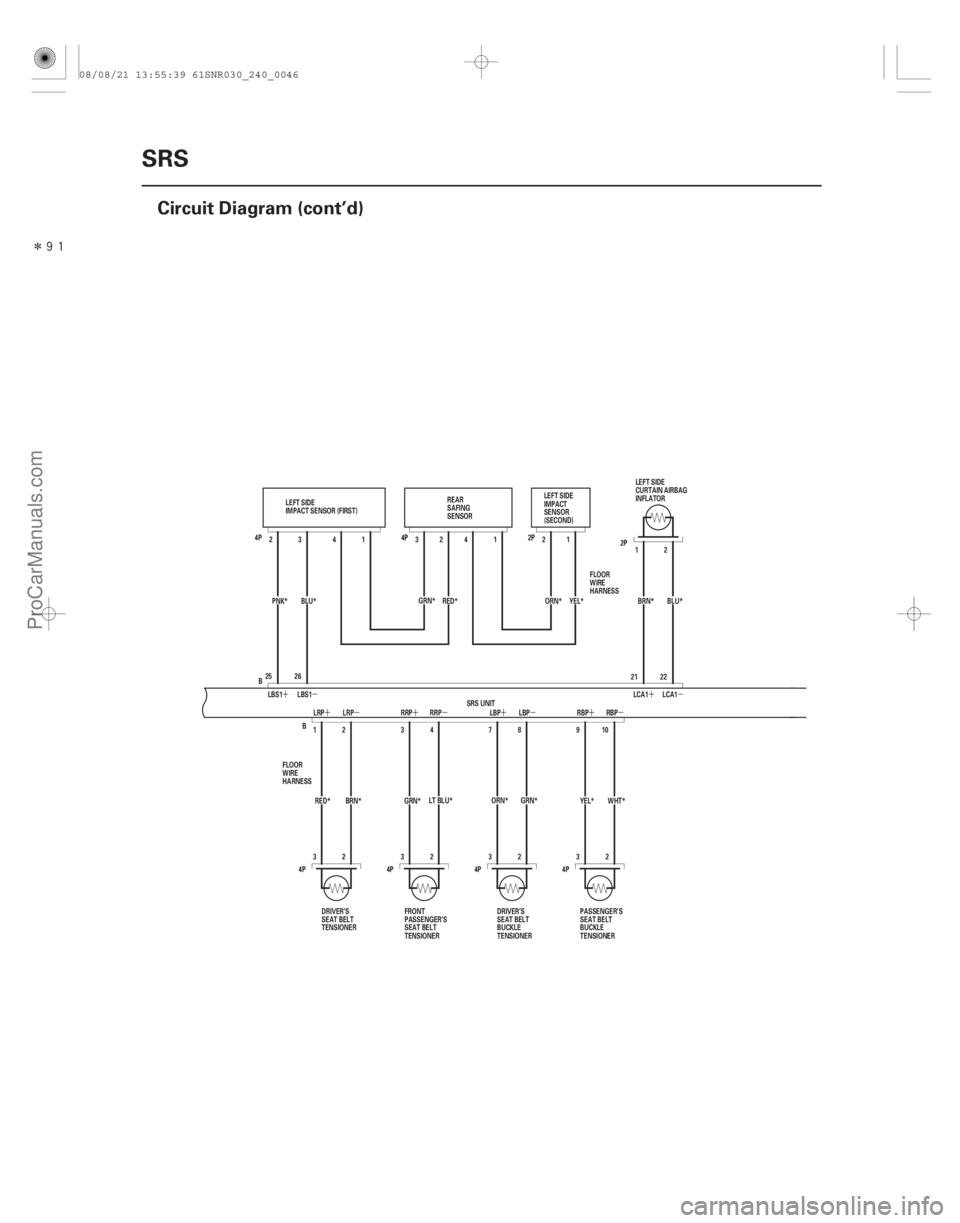
Circuit Diagram (cont’d)
GRN*
RED* LT BLU*
BRN* GRN*
WHT*
ORN*
YEL*BLU*
BRN*
ORN* YEL*
RED*
GRN*
PNK* BLU* 1
41 2
2P
4P
4P
4P
4P 2
3
32 8
7910 22
21 12
4P
4P
32
41
B 4
3
12
2
332
B
26
25 3
2
SRS UNIT
LEFT SIDE
IMPACT SENSOR (FIRST)
DRIVER’S
SEAT BELT
TENSIONER REAR
SAFING
SENSOR
LEFT SIDE
CURTAIN AIRBAG
INFLATOR
DRIVER’S
SEAT BELT
BUCKLE
TENSIONER
FRONT
PASSENGER’S
SEAT BELT
TENSIONER PASSENGER’S
SEAT BELT
BUCKLE
TENSIONER
LEFT SIDE
IMPACT
SENSOR
(SECOND)
FLOOR
WIRE
HARNESS2P
FLOOR
WIRE
HARNESS
LBS1
LRP
LRP RRP RRP LBP LBP RBPRBP
LBS1
LCA1 LCA1
08/08/21 13:55:39 61SNR030_240_0046
ProCarManuals.com
DYNOMITE -2009-
Page 2727 of 2893
����
�µ
�´�µ �´
�´�µ
�µ
�´
24-47
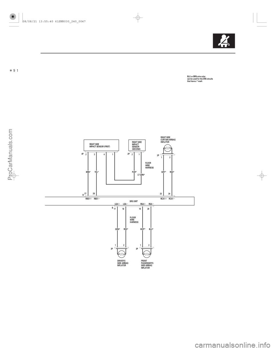
WHT*
GRN* BLU* RED* RED*
GRY*
PUR*
LT GRN*
YEL*
BRN*
20
19
17 18
2
112
2P 2P
23
27 28
B 1
41 2
4P 2P
2
1
23 24
B SRS UNIT RIGHT SIDE
CURTAIN AIRBAG
INFLATOR
RIGHT SIDE
IMPACT
SENSOR
(SECOND)
RIGHT SIDE
IMPACT SENSOR (FIRST)
FRONT
PASSENGER’S
SIDE AIRBAG
INFLATOR
DRIVER’S
SIDE AIRBAG
INFLATOR FLOOR
WIRE
HARNESS
FLOOR
WIRE
HARNESS 2P BLU or BRN wire color
can be used for the SRS circuits
that have a * mark
LSA
LSA RSA RSA
RBS1 RBS1
RCA1
RCA1
08/08/21 13:55:40 61SNR030_240_0047
ProCarManuals.com
DYNOMITE -2009-
Page 2800 of 2893
����
�µ
�µ
�µ
�µ �µ
�µ
DTC 41-1x (‘‘x’’ can be 0 thru 9 or A thru F):
Special Tools Required
YES
NO
YES
NO YES
NO
24-120SRS
DTC Tr")
���
����
�(�#�'��������� �����
�������'���
�
�-�������)����
�µ
�µ
�µ
�µ �µ
�µ
DTC 41-1x (‘‘x’’ can be 0 thru 9 or A thru F):
Special Tools Required
YES
NO
YES
NO YES
NO
24-120SRS
DTC Troubleshooting (cont’d)
A
SRS UNIT CONNECTOR A (28P)
No Signal From the Left Front Impact Sensor
SRS inflator simulator 07SAZ-TB4011A
SRS simulator lead L 070AZ-SNAA300
NOTE: Before doing this troubleshooting procedure,
review SRS Precautions and Procedures (see page
24-13), General Troubleshooting Information (see page
24-22), and Battery Terminal Disconnection and
Reconnection (see page 22-68). 1. Clear the DTC memory (see page 24-23).
2. Turn the ignition switch to ON (II), and check that the SRS indicator comes on for about 6 seconds
and then goes off.
Go to step 3.
Intermittent failure, system is OK at this time.
Go to Troubleshooting Intermittent Failures
(see page 24-24). If another DTC is indicated,
troubleshoot the DTC.
3. Turn the ignition switch to LOCK (0).
4. Disconnect the negative cable from the battery, then wait at least 3 minutes.
5. Check the connections between SRS unit connector A (28P) and the SRS unit, between the engine
compartment wire harness 2P connector and the
left front impact sensor (see page 24-11), and at
connector C203 (see page 22-22).
Go to step 6.
Repair the poor connections, clear the DTC,
and retest. If DTC 41-1x is still present, go to step 6. 6. Disconnect the engine compartment wire harness
2P connector (A) from the left front impact sensor.
7. Disconnect SRS unit connector A (28P) from the SRS unit (see step 9 on page 24-21).
8. Measure the resistance between SRS unit connector A (28P) terminals No. 15 and No. 27.
There should be an open circuit or at least 1 M .
Go to step 9.
Short in the engine compartment wire
harness or dashboard wire harness; replace the
faulty harness, then clear the DTC.
Wire side of female terminals
Does the SRS indicator stay on, and is DT C 41-1x indicated?
Ar e t he connect i ons OK ? Is the resistance as specif ied?
08/08/21 13:58:25 61SNR030_240_0120
ProCarManuals.com
DYNOMITE -2009-
Page 2802 of 2893
����
�µ
�µ �µ
�µ
�µ
�µ
YES
NO
Special Tools Required
YES
NO
YES
NO
DTC 42-1x (‘‘x’’ can be 0 thru 9 or A thru F):
24-12224-122SRS
DTC T")
����
�(�#�'��������� �����
�������'�����
�-�������)����
�µ
�µ �µ
�µ
�µ
�µ
YES
NO
Special Tools Required
YES
NO
YES
NO
DTC 42-1x (‘‘x’’ can be 0 thru 9 or A thru F):
24-12224-122SRS
DTC Troubleshooting (cont’d)
SRS UNIT CONNECTOR A (28P)
15. Measure the resistance between SRS unit
connector A (28P) terminals No. 15 and No. 27.
There should be less than 1.0 .
Faulty left front impact sensor or SRS unit;
replace the left front impact sensor (see page
24-210), then clear the DTC. If the problem is still
present, replace the SRS unit (see page 24-203).
Poor connection at C 203, open in engine
compartment wire harness, or open in dashboard
wire harness. Inspect C203 (see page 22-22). If it is
OK, replace the faulty harness, then clear the
DTC. SRS inflator simulator 07SAZ-TB4011A
SRS simulator lead L 070AZ-SNAA300
NOTE: Before doing this troubleshooting procedure,
review SRS Precautions and Procedures (see page
24-13), General Troubleshooting Information (see page
24-22), and Battery Terminal Disconnection and
Reconnection (see page 22-68).
1. Clear the DTC memory (see page 24-23).
2. Turn the ignition switch to ON (II), and check that the SRS indicator comes on for about 6 seconds
and then goes off.
Go to step 3.
Intermittent failure, system is OK at this time.
Go to Troubleshooting Intermittent Failures
(see page 24-24). If another DTC is indicated,
troubleshoot the DTC.
3. Turn the ignition switch to LOCK (0).
4. Disconnect the negative cable from the battery, then wait at least 3 minutes.
5. Check the connections between SRS unit connector A (28P) and the SRS unit, between the engine
compartment wire harness 2P connector and the
right front impact sensor (see page 24-11), and at
connector C203 (see page 22-22).
Go to step 6.
Repair the poor connections, clear the DTC,
and retest. If DTC 42-1x is still present, go to step 6.
No Signal From the Right Front Impact
Sensor
Wire side of female terminals
Is the resistance as specif ied?
Does the SRS indicator stay on, and is DT C 42-1xindicated?
Ar e t he connect i ons OK ?
08/08/21 13:59:39 61SNR030_240_0122
ProCarManuals.com
DYNOMITE -2009-
Page 2803 of 2893
 SRS UNIT CONNECTOR A (28P)
6. Disconnect the engine compartment wire harness
2P connector (A) from the right front impac")
���
��������
�µ
�µ �µ
�µ
YES
NO YES
NO
24-123
A
SRS UNIT CONNECTOR A (28P) SRS UNIT CONNECTOR A (28P)
6. Disconnect the engine compartment wire harness
2P connector (A) from the right front impact sensor.
7. Disconnect SRS unit connector A (28P) from the SRS unit (see step 9 on page 24-21).
8. Measure the resistance between SRS unit connector A (28P) terminals No. 16 and No. 28.
There should be an open circuit or at least 1 M .
Go to step 9.
Short in the engine compartment wire
harness or dashboard wire harness; replace the
faulty harness, then clear the DTC. 9. Measure the resistance between body ground and
SRS unit connector A (28P) terminals No. 16 and
No. 28, individually. There should be an open
circuitoratleast1M .
Go to step 10.
Short to ground in the dashboard wire
harness or the engine compartment wire harness;
replace the faulty harness, then clear the DTC.
10. Reconnect the negative cable to the battery.
11. Turn the ignition switch to ON (II).
(cont’d)
Wire side of female terminals Wire side of female terminals
Is the resistance as specif ied?
Is the resistance as specif ied?
08/08/21 13:59:40 61SNR030_240_0123
ProCarManuals.com
DYNOMITE -2009-