Page 1607 of 2893
�����
�´�´
�´
�´ �´
�´
�´
19-115
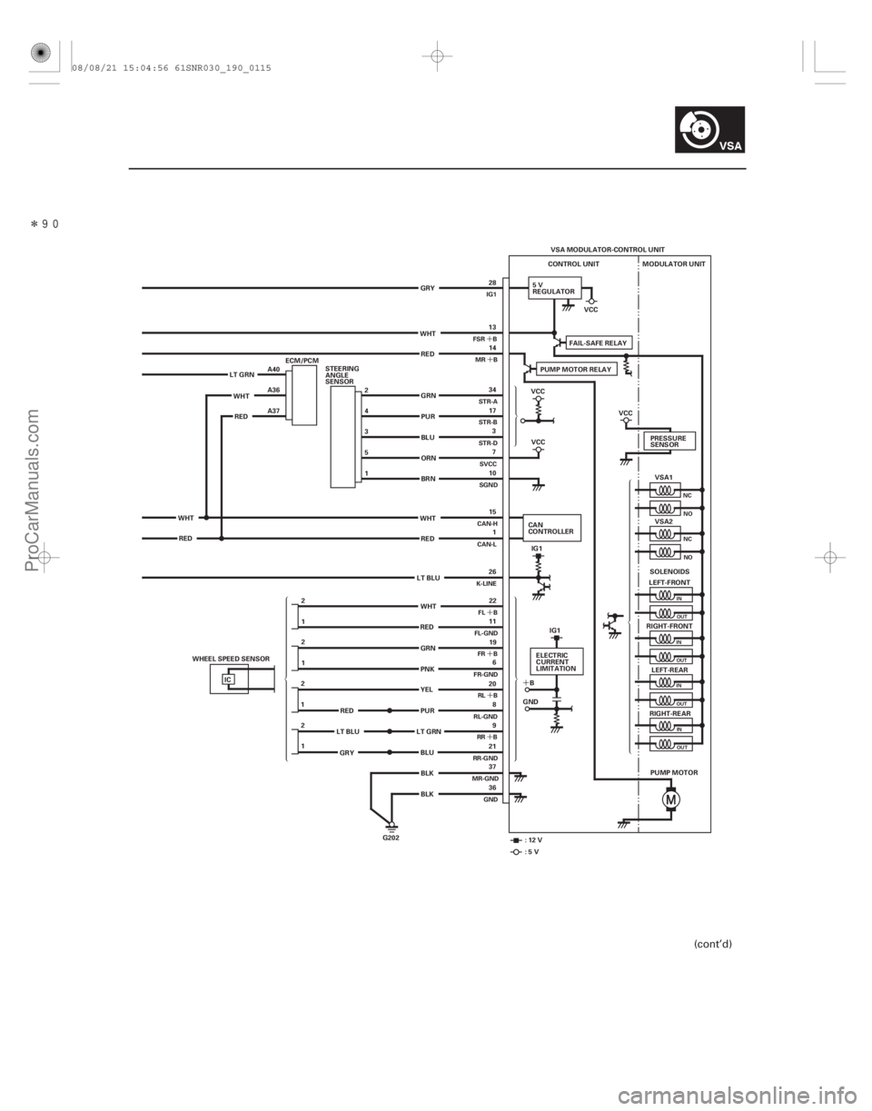
VSA MODULATOR-CONTROL UNIT
CONTROL UNIT
5V
REGULATOR MODULATOR UNIT
VSA1
VSA2
LEFT-FRONT
RIGHT-FRONT LEFT-REAR
RIGHT-REAR
PUMP MOTOR
G202 PRESSURE
SENSOR
SOLENOIDS
IC 13
14
22
11 19 6
20 8
9
21
37
36 34
17 3
7
10
15 1
26
1 2 1
2
2
1
1 2 28
WHT RED
GRN
PUR
BLU
ORN
BRN
WHT RED
LT BLU
GRN
PNK
BLK BLK
LT GRN
WHTRED A40
A36
A37
WHT RED 2
4
3
5
1
STEERING
ANGLE
SENSOR
PUR
LT GRN
RED
LT BLU
GRY PUMP MOTOR RELAY
FAIL-SAFE RELAY
VCC
VCC
IG1
CAN
CONTROLLER
:12V :5V VCC
ELECTRIC
CURRENT
LIMITATION
B
GND IG1
VCC
GRY
BLU YEL
RED
WHT
ECM/PCM
WHEEL SPEED SENSOR
NC NO
NCNO
IN
OUT
IN OUT
IN OUT
INOUT
FSR B MR B
FL B
FL-GND FR B
FR-GND
RL B
RL-GND RR B
RR-GND
MR-GND
GND
STR-A
STR-B
STR-D
SVCC
SGND
CAN-H
CAN-L
K-LINE IG1
(cont’d)
08/08/21 15:04:56 61SNR030_190_0115
ProCarManuals.com
DYNOMITE -2009-
Page 1608 of 2893
���
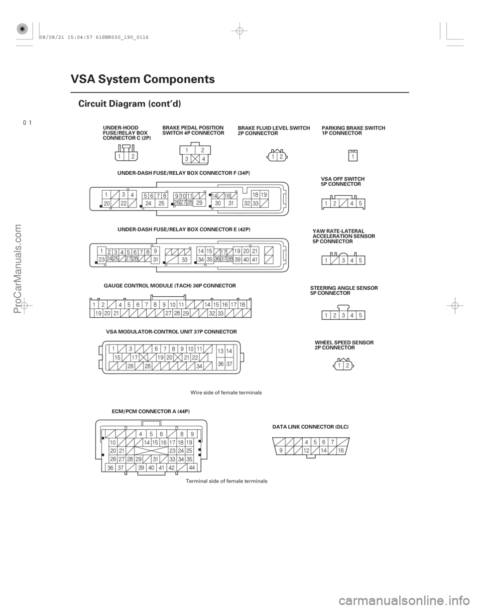
19-116VSA System Components
Circuit Diagram (cont’d)
BRAKE PEDAL POSITION
SWITCH 4P CONNECTOR
PARKING BRAKE SWITCH
1P CONNECTOR
DATA LINK CONNECTOR (DLC) VSA OFF SWITCH
5P CONNECTOR
YAW RATE-LATERAL
ACCELERATION SENSOR
5P CONNECTOR
STEERING ANGLE SENSOR
5P CONNECTOR
BRAKE FLUID LEVEL SWITCH
2P CONNECTOR
UNDER-HOOD
FUSE/RELAY BOX
CONNECTOR C (2P)
WHEEL SPEED SENSOR
2P CONNECTOR
ECM/PCM CONNECTOR A (44P)
GAUGE CONTROL MODULE (TACH) 36P CONNECTOR
VSA MODULATOR-CONTROL UNIT 37P CONNECTOR UNDER-DASH FUSE/RELAY BOX CONNECTOR F (34P)
UNDER-DASH FUSE/RELAY BOX CONNECTOR E (42P)
Wire side of female terminals
Terminal side of female terminals
08/08/21 15:04:57 61SNR030_190_0116
ProCarManuals.com
DYNOMITE -2009-
Page 1624 of 2893
����
�µ
�µ �µ
�µ
DTC 27-21:
DTC 27-22:
YES
NO YES
NO
19-132VSA System Components
DTC Troubleshooting (cont’d)
STEERING ANGLE SENSOR 5P C")
�´�µ
���
�(�#�'��������� �����
�������'�������
�������)����
�µ
�µ �µ
�µ
DTC 27-21:
DTC 27-22:
YES
NO YES
NO
19-132VSA System Components
DTC Troubleshooting (cont’d)
STEERING ANGLE SENSOR 5P CONNECTOR
STR-A (GRN) STR-B (PUR)
Steering Angle Sensor Stuck
Neutral Position
Steering Angle Sensor Stuck
Offset Position
1. Turn the ignition switch to ON (II).
2. Turn the steering wheel left and right 90 degrees or
more. Check the STEERING ANGLE in the VSA
DATA LIST with the HDS.
Intermittent failure, the system is OK at this
time. Check for loose terminals between the
steering angle sensor 5P connector and the VSA
modulator-control unit 37P connector. Refer to
intermittent failures troubleshooting (see page
19-98).
Go to step 3.
3. Turn the ignition switch to LOCK (0).
4. Disconnect the steering angle sensor 5P connector.
5. Disconnect the VSA modulator-control unit 37P connector (see step 2 on page 19- 171).6. Check for continuity between body ground and
steering angle sensor 5P connector terminals No. 2
and No. 4 individually.
Repair short to body ground in the wire
between the steering angle sensor and the VSA
modulator-control unit.
Go to step 7.
Wire side of female terminals
I s t her e 90 ° or mor e, and 90 ° or l ess?
Is there continuity?
08/08/21 15:05:54 61SNR030_190_0132
ProCarManuals.com
DYNOMITE -2009-
Page 1627 of 2893
�����(�#���������� �����
����������������������)����
�µ
�µ �µ
�µ
DTC 27-23: DTC 27-24:
YES
NO YES
NO
19-13519-135
Steering Angle Sensor Counter
Malf")
�(�#�'��������� �����
�������'���������������)�����(�#�'��������� �����
�������'���������������)����
�µ
�µ �µ
�µ
DTC 27-23: DTC 27-24:
YES
NO YES
NO
19-13519-135
Steering Angle Sensor Counter
Malfunction Steering Angle Sensor Exchange
Malfunction
1. Turn the ignition switch to ON (II).
2. Clear the DTC with the HDS.
3. Turn the ignition switch to LOCK (0), then turn it to
ON (II) again.
4. Turn the steering wheel from lock to lock.
5. Check for DTCs with the HDS.
Replace the steering angle sensor (see page
19-168).
Intermittent failure, the system is OK at this
time. 1. Turn the ignition switch to ON (II), and set the front
wheels to the straight ahead position.
2. Turn the steering wheel one turn to the left. Check the STEERING ANGLE in the VSA DATA LIST with
the HDS.
Intermittent failure, the system is OK at this
time.
Replace the steering angle sensor (see page
19-168).
Is DTC 27-23 indicated? Is t her e about 288 d egr ees t o 432 d egr ees
posi t i v e?
08/08/21 15:05:55 61SNR030_190_0135
ProCarManuals.com
DYNOMITE -2009-
Page 1647 of 2893
�����(�#���������� �����
������������
���������)����
�µ
�µ �µ
�µ
�µ
�µ
DTC 81-3D:
DTC 81-3E:
DTC 81-59: DTC 83-13:
DTC 83-14:
YES
NO YES
NO
YES
NO")
�(�#�'��������� �����
�������'���
�����������)�����(�#�'��������� �����
�������'�����
���������)����
�µ
�µ �µ
�µ
�µ
�µ
DTC 81-3D:
DTC 81-3E:
DTC 81-59: DTC 83-13:
DTC 83-14:
YES
NO YES
NO
YES
NO
19-15519-155
Central Processing Unit (CPU)
Internal Circuit Malfunction
Central Processing Unit (CPU)
Internal Circuit Malfunction
Central Processing Unit (CPU)
Internal Circuit Malfunction ECM/PCM Communication Error
ECM/PCM Communication Error
1. Turn the ignition switch to ON (II).
2. Clear the DTC with the HDS.
3. Start the engine.
4. Turn the steering wheel from lock to lock several
times.
5. Check for DTCs with the HDS.
Replace the VSA modulator-control unit
(see page 19-171).
Intermittent failure, the system is OK at this
time. 1. Turn the ignition switch to ON (II).
2. Clear the DTC with the HDS.
3. Test-drive the vehicle.
NOTE: Drive the vehicle on the road, not on a lift.
4. Check for DTCs with the HDS.
Go to step 5.
Intermittent failure, the system is OK at this
time. Check for loose terminals between the ECM/
PCM connector A (44P) and the VSA modulator-
control unit 37P connector. Refer to intermittent
failures troubleshooting (see page 19-98).
5. Turn the ignition switch to LOCK (0).
6. Update the ECM/PCM if it does not have the latest software (see page 11-227), or substitute a known-
good ECM/PCM (see page 11-7).
7. Turn the ignition switch to ON (II).
8. Clear the DTC with the HDS.
9. Test-drive the vehicle. NOTE: Drive the vehicle on the road, not on a lift.
10. Check for DTCs with the HDS.
Replace the VSA modulator-control unit
(see page 19-171).
If the ECM/PCM was updated, troubleshooting
is complete. If the ECM/PCM was substituted,
replace the original ECM/PCM (see page 11-228).
I s DT C 81-3D, 81-3E , or 81-5 9 i nd i cat ed ? I s DT C 83-13 or 83-14 i nd i cat ed ?
I s DT C 83-13 or 83-14 i nd i cat ed ?
08/08/21 15:06:41 61SNR030_190_0155
ProCarManuals.com
DYNOMITE -2009-
Page 1660 of 2893
����
19-168VSA System Components
Steering Angle Sensor Replacement
A
B
C
NOTE: Do not damage or drop the combination switch as the steering angle sens")
���
�(�#�'���������������
���������������
� �����)����
19-168VSA System Components
Steering Angle Sensor Replacement
A
B
C
NOTE: Do not damage or drop the combination switch as the steering angle sensor is sensitive to shock and vibration.
1. With the wheels in the straight-ahead position and the steering wheel centered, remove the steering wheel (see page 17-6).
2. Remove the steering column covers (see page 17-9) and the cable reel (see page 24-200).
3. Remove the combination switch assembly (see step 11 on page 17-11).
4. Remove the combination light switch (A) and the wiper/washer switch (B) from the combination switch body assembly (C).
5. Install the combination switch body assembly in the r everse order of removal.
NOTE: Do not remove the steering angle sensor from the combination switch body.
When installing the cable reel, set the turn signal canceling sleeve position so that the arrow points straight up (see page 24-201).
When installing the combination switch, tighten the m ounting screws to the specified torque and sequence
shown (see page 17-12).
08/08/21 15:06:45 61SNR030_190_0168
ProCarManuals.com
DYNOMITE -2009-
Page 1661 of 2893
���� ���
�(�#����������������
�����������������������)���
19-16919-169
Yaw Rate-Lateral Acceleration
Sensor Replacement VSA Sensor Neutral Position")
���
�(�#�'���������������
�������������
�
� �����)���� ���
�(�#�'���������������
�����������������������)���
19-16919-169
Yaw Rate-Lateral Acceleration
Sensor Replacement VSA Sensor Neutral Position
Memorization
AB
9.8 N·m
(1.0 kgf·m, 7.2 lbf·ft) A
NOTE:
Do not damage or drop the sensor as it is sensitive.
Do not use power tools when replacing the sensor.
1. Turn the ignition switch to LOCK (0).
2. Remove the center console (see page 20-92).
3. Remove the yaw rate-lateral acceleration sensor (A) mounting bolts.
4. Pull out the yaw rate-lateral acceleration sensor, then disconnect the sensor connector (B).
5. Install the yaw rate-lateral acceleration sensor in the reverse order of removal.
6. Do the VSA sensor neutral position memorization (see page 19-169). NOTE: Do not press the brake pedal during this
procedure.
1. Park the vehicle on a flat and level surface, with the steering wheel in the straight ahead position.
2. With the ignition switch in LOCK (0), connect the HDS to the data link connector (DLC) (A) under the
driver’s side of the dashboard.
3. Turn the ignition switch to ON (II).
4. Make sure the HDS communicates with the vehicle and the VSA modulator-control unit. If it doesn’t
troubleshoot the DLC circuit (see page 11-204).
5. Select VSA ADJUSTMENT with the HDS, and follow the screen prompts.
NOTE: See the HDS Help menu for specific
instructions.
6. Turn the ignition switch to LOCK (0).
08/08/21 15:06:46 61SNR030_190_0169
ProCarManuals.com
DYNOMITE -2009-
Page 1762 of 2893

Cushion tape B: P/N 91902-SNA-003 50x50mm(1.97x1.97in.)
20-86Interior Trim
Headliner Removal/Installation (cont’d)
B
Fastener Locati")
���
����
Cushion tape A: P/N 91903-SNA-003
100x50mm(3.94x1.97in.)
Cushion tape B: P/N 91902-SNA-003 50x50mm(1.97x1.97in.)
20-86Interior Trim
Headliner Removal/Installation (cont’d)
B
Fastener Locations
:Clip,2(White)
A B
C
B
C
F
Without moonroof
BD
C
D
C
D
A
ED
With moonroof
C
D
Fastener Locations
: Cushion tape, 8
BB
BB
B B
B
A
A, B
13. Lower the headliner (A).
–1 Remove the front door opening seals (B) andrear door opening seals (C) from each roof
portion.
–2 With the help of an assistant, detach the rear clips by pulling the rear portion of the
headliner down.
–3 With moonroof: Release the Velcro fastener (D) by lowering the headliner.
–4 With moonroof: Release the hook (E) of the moonroof by moving the headliner rearward.
14. Lower the front of the headliner below the steering wheel. Rotate the liner, and pull it along with the
roof wire harness (F) (without moonroof) out
through the passenger’s front door. Do not bend
the liner. Bending the liner will crease and damage
it. 15. If necessary, remove the cushion tape (A, B)
fastening the roof wire harness (C) to the headliner
(D), then remove them from the headliner.
08/08/21 15:01:41 61SNR030_200_0088
ProCarManuals.com
DYNOMITE -2009-