Page 1329 of 2893
����
17-6 Steering
Steering Wheel Removal
A
B
A
D B
C
SRS components are located in this area. Review the
SRS component locations (see page")
���
����
����
�(�#�'���������������������������
���
� �����)����
17-6 Steering
Steering Wheel Removal
A
B
A
D B
C
SRS components are located in this area. Review the
SRS component locations (see page 24-11) and the
precautions and procedures (see page 24-13) before
doing repairs or service.
1. Do the battery terminal disconnection procedure (see page 22-68).
2. Align the front wheels straight ahead, then remove the driver’s airbag from the steering wheel
(see page 24-188).
3. Disconnect the cable reel subharness connector (A).
4. Loosen the steering wheel bolt (B). 5. Install a commercially available steering wheel
puller (A) on the steering wheel (B). Free the
steering wheel from the steering column shaft by
turning the pressure bolt (C) of the puller.
Note these items when removing the steering
wheel: Do not tap on the steering wheel or the steering column shaft when removing the steering wheel.
If you thread the puller bolts (D) into the wheel hub more than five threads, the bolts will hit the
cable reel and damage it. To prevent this, install
a pair of jam nuts five threads up on each puller
bolt.
6. Remove the steering wheel puller, then remove the steering wheel bolt and steering wheel from the
steering column.
08/08/21 14:53:14 61SNR030_170_0007
ProCarManuals.com
DYNOMITE -2009-
Page 1330 of 2893
���
�(�#�'���������������������������
���
�"�����)����
�µ�´
17-7
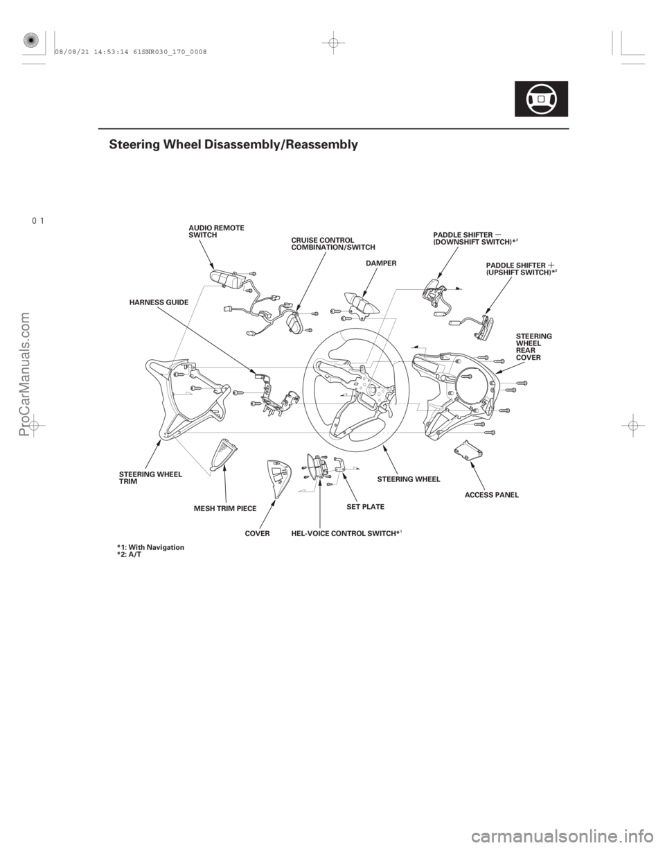
Steering Wheel Disassembly/Reassembly
DAMPER
CRUISE CONTROL
COMBINATION/SWITCH
AUDIO REMOTE
SWITCH
PADDLE SHIFTER
(DOWNSHIFT SWITCH)*
HARNESS GUIDE STEERING
WHEEL
REAR
COVER
STEERING WHEEL
TRIM MESH TRIM PIECECOVERHEL-VOICE CONTROL SWITCH* SET PLATESTEERING WHEEL
ACCESS PANELPADDLE SHIFTER
(UPSHIFT SWITCH)*
*1: With Navigation
*2: A/T
2
1 2
08/08/21 14:53:14 61SNR030_170_0008
ProCarManuals.com
DYNOMITE -2009-
Page 1331 of 2893
����
17-9
Column Cover Removal and Installation
I K
A B
C D
E
F
G
HK
J
B A
NOTE: Take care not to scratch or damage the column covers.
Do not")
���
����
�(�#�'��������������������������������� �����)����
17-9
Column Cover Removal and Installation
I K
A B
C D
E
F
G
HK
J
B A
NOTE: Take care not to scratch or damage the column covers.
Do not pry the cover surface with any tools.
1. Release the lock lever (A), and adjust the steering column to full tilt down position and to the full
telescopic out position.
2. Insert a suitable sized screwdriver or equivalent tool (B) along the guide rib (C) into the lever hole
(D) in the lower column cover (E).
3. Release the hook (F) located on the left side of the upper column cover (G). A right side hook (H) of the
upper column cover can’t be released from the
inside. 4. Turn the steering wheel to the left, and release the
left pawl (I) of the upper column cover while
pushing the lower column cover from the front side.
5. Turn the steering wheel to the right, and release the right pawl (J) of the upper column cover in the
same way as in step 4.
6. Remove the cover by lightly pulling it up by releasing the right side hook of the upper column
cover.
Carefully release the pawls, note the hooks (K)
may break when the upper column cover is
pulled up too hard.
7. Remove the three screws, then remove the lower column cover (A).
8. Install the upper and lower column cover in the reverse order of removal, and push the hooks into
place securely.
08/08/21 14:53:15 61SNR030_170_0010
ProCarManuals.com
DYNOMITE -2009-
Page 1332 of 2893
����
Removal
17-10 Steering
Steering Column Removal and Installation
Normal position
Out of position
A
A
A
A B
C D
SRS components are locate")
���
����
����
�(�#�'���������������������������
���
� �����)����
Removal
17-10 Steering
Steering Column Removal and Installation
Normal position
Out of position
A
A
A
A B
C D
SRS components are located in this area. Review the
SRS component locations (see page 24-11) and the
precautions and procedures (see page 24-13) before
doing repairs or service.
Be careful not to pull the bracket (A) on the front
side of the steering column out of its normal
position. If the bracket accidentally comes out,
replace the steering column as an assembly.
1. Do the battery terminal disconnection procedure (see page 22-68).
2. Remove the driver’s airbag (see page 24-188), and the steering wheel (see page 17-6).
3. Remove the driver’s dashboard undercover (see page 20-103).
4. Remove the column covers (see page 17-9). 5. Remove the steering joint cover (A).
6. Release the lock lever, and adjust the steering
column to the full tilt up position, and to the full
telescopic in position.
7. Tighten the lock lever.
8. Hold the lower slide shaft (A) on the column with a piece of wire (B) between the joint yoke (C) of the
lower slide shaft and joint yoke (D) of the upper
shaft to prevent the slider shaft from pulling out.
9. Release the lock lever, and adjust the steering column to the full telescopic out position, then
tighten the lock lever.
NOTE: Do not release the lock lever when removing
the steering column from the frame.
08/08/21 14:53:16 61SNR030_170_0011
ProCarManuals.com
DYNOMITE -2009-
Page 1335 of 2893
.
6. Install the steering wheel (see page 17-8), and thedriver’s airbag (see page 24-188).
7. Install the column covers (see page 17-9).
8. Instal")
����
17-13
A
5. Install the steering joint cover (A).
6. Install the steering wheel (see page 17-8), and thedriver’s airbag (see page 24-188).
7. Install the column covers (see page 17-9).
8. Install the driver’s dashboard undercover (see page 20-103). 9. Do the battery terminal reconnection procedure
(see page 22-68), and do these tasks:
Turn the ignition switch to ON (II), and check that the SRS indicator comes on for about 6 seconds
and then goes off.
Make sure the horn and turn signal switches work properly.
Make sure the steering wheel switches work properly.
10. After installation, do these checks: Check the steering wheel spoke angle. If thesteering spoke angles to the right and left are not
equal (steering wheel and rack are not centered),
correct the engagement of the joint/pinion shaft
splines.
Set the steering column to the center tilt position, and to the center telescopic position, then do the
front toe inspection (see page 18-5).
08/08/21 14:53:18 61SNR030_170_0014
ProCarManuals.com
DYNOMITE -2009-
Page 1336 of 2893
���
���
����
�(�#����������������������������
���
� �����)����
17-1417-14 Steering
Steering Column Inspection
Steering Lock Replacement
D
B A
E
F
B")
���
�(�#�'���������������������������
���
�"�����)���
���
����
�(�#�'���������������������������
���
� �����)����
17-1417-14 Steering
Steering Column Inspection
Steering Lock Replacement
D
B A
E
F
B C
A
B
1. Remove the steering column (see page 17-10).
2. Do these checks: Check the steering column ball bearing (A) andthe steering joint (B) for play and proper
movement. If any bearing is noisy or has
excessive play, replace the steering column as an
assembly.
Check the lower slide shaft (C) for smooth movement in and out. If the lower slide shaft is
removed, slip it into the upper shaft by aligning
the paint or stamped marks (D). If it sticks or
binds, replace the steering column as an
assembly.
Check the sliding capsules (E) for distortion or breakage. If there is distortion or breakage,
replace the steering column as an assembly.
Check the tilt mechanism and telescopic mechanism for movement and damage.
Check the absorbing plates (F) for distortion or breakage. If there is distortion or breakage,
replace the steering column as an assembly.
3. Install the steering column (see page 17-12). 1. Remove the steering column (see page 17-10).
2. Center-punch both of the two shear bolts, and drill
the heads of the bolts off with a 5 mm (0.20 in.) drill
bit. Be careful not to damage the switch body when
removing the shear bolts.
3. Remove the shear bolts from the switch body.
4. Install the switch body without the key inserted.
5. Loosely tighten the new shear bolts.
6. Insert the ignition key, and check for proper operation of the steering wheel lock and that the
ignition key turns freely.
7. Tighten the shear bolts (A) until the hex heads (B) twist off.
8. Rewrite the immobilizer control unit-receiver (see page 22-329), and make sure the immobilizer
system works properly.
9. Install the steering column (see page 17-12).
08/08/21 14:53:18 61SNR030_170_0015
ProCarManuals.com
DYNOMITE -2009-
Page 1337 of 2893
����
�
�
Special Tools Required
Specified return angle: 7 3 °
17-15
Rack Guide Adjustment
AB
07MAA-SL0020A
A
B A
73°
B
44 N·m
(4.5 kg")
���
��������
�(�#�'���������������������������
���
�"�����)����
�
�
Special Tools Required
Specified return angle: 7 3 °
17-15
Rack Guide Adjustment
AB
07MAA-SL0020A
A
B A
73°
B
44 N·m
(4.5 kgf·m, 33 lbf·ft)
Locknut wrench, 43 mm 07MAA-SL0020A1. Set the wheels in the straight ahead position.
2. Loosen the rack guide screw locknut (A) with the locknut wrench, then remove the rack guide screw
(B).
3. Remove the old sealant from the rack guide screw (A), and apply new sealant (Three Bond 1215 or
Loctite 5699) to the middle of the threads (B).
Loosely install the rack guide screw on the steering
gearbox.
NOTE: If more than 5 minutes has passed after
applying the sealant, remove the old sealant and
residue, and reapply new sealant. 4. Tighten the rack guide screw (A) to 25 N·m
(2.5 kgf·m, 18 lbf·ft), then loosen it.
5. Retighten the rack guide screw to 3.9 N·m (0.4 kgf·m, 2.9 lbf·ft), then back it off to the specified
angle.
6. Hold the rack guide screw stationary with a wrench, and tighten the locknut (B) by hand until it’s fully
seated.
7. Install the locknut wrench on the locknut, and hold the rack guide screw stationary with a wrench.
Tighten the locknut to the specified torque.
8. Check for unusual steering effort through the complete turning range.
9. Check the steering wheel rotational play (see page 17-4) and the power assist (see page 17-4).
08/08/21 14:53:19 61SNR030_170_0016
ProCarManuals.com
DYNOMITE -2009-
Page 1338 of 2893
���
Special Tools Required
17-16
Steering
Tie-rod End Ball Joint Boot Replacement
C
D
D
A
B
E A
B
07JAF-SH20330
Bushing base 07JAF-SH20330
1. Di")
���
����
�(�#�'�������������������������������
� �����)���
Special Tools Required
17-16
Steering
Tie-rod End Ball Joint Boot Replacement
C
D
D
A
B
E A
B
07JAF-SH20330
Bushing base 07JAF-SH20330
1. Disconnect the tie-rod end ball joint from the knuckle (see step 17 on page 17-67).
2. Remove the tie-rod end from the rack end.
3. Remove the tie-rod ball joint boot from the tie-rod end, and wipe the old grease off the ball pin.
4. Pack the lower area of the ball pin (A) with fresh multipurpose grease.
5. Pack the interior of the new tie-rod end ball joint boot (B) and lip (C) with fresh multipurpose grease.
Note these items when installing new grease: Keep grease off the boot mounting area (D) and the tapered section (E) of the ball pin.
Do not allow dust, dirt, or other foreign materials to enter the boot. 6. Install the new tie-rod end ball joint boot (A) using
the bushing base. The boot must not have a gap at
the boot installation sections (B). After insta lling the
boot, check the ball pin tapered section for grease
contamination, and wipe it if necessary.
7. Install the tie-rod end to the rack end.
8. Connect the tie-rod end ball joint to the knuckle (see step 25 on page 17-76).
9. Check the wheel alignment, and adjust it if necessary (see page 18-5).
08/08/21 14:53:19 61SNR030_170_0017
ProCarManuals.com
DYNOMITE -2009-