Page 2192 of 2893

OFF")
�´�µ
���
The Indicator Drive Circuit Check
Switch Input Check
The Beeper Drive Circuit Check
The LCD Segment Check
The Gauge Drive Circuit Check
22-242Gauges
Self-diagnostic Function (cont’d)
OFF ON
OFF ON
OFF ON
OFF ON
Gauge needles
Beeper
5sec.
Self-diagnostic
mode
SEL/RESET
SWITCH
When entering the self-diagnostic mode, the following indicators blink:
A/T gear position indicator, ABS indicator, brake system indicator, charging system indicator, cruise control indicator,
cruise main indicator, door indicator, DRL indicator, EPS indicator, fog light indicator , high beam indicator,
immobilizer indicator, lights-on indicator, low fuel indicator, low oil pressure indicator, low tire pressure indicator ,
maintenance minder indicator, malfunction indicator lamp (MIL), REV limit indicator (TYPE S model), seat belt
reminder indicator, security indicator, side airbag cutoff indicator, SRS indicator, TPMS indicator , trunk indicator,
VSA activation indicator , VSA indicator , and washer fluid level indicator.
1: ’07 TYPE S and ’08-09 models
2: ’08-09 models
3: TYPE S and ’08 Premium and ’09 models
At the initial stage of the self-diagnostic function, the beep sounds intermittently, the beeper sounds continuously
when any of the following switch inputs are switched from OFF to ON:
Cruise control main, dash lights brightness controller volume ( ), ( ) button, mph km/h switch, parking brake switch,
SEL/RESET switch, SET, RESUME, CANCEL switches, and VSA OFF switch . : ’07 TYPE S and ’08-09 models
When entering the self-diagnostic mode, the beeper sounds five times.
When entering the self-diagnostic mode, all the segments blink five times.
When entering the self-diagnostic mode, the tachometer needle sweeps from the minimum position to maximum
position, then returns to the minimum position.
NOTE:
After the beeper stops sounding and the gauge needle returns to the minimum position, pushing the SEL/RESET
switch starts the Beeper Drive Circuit Check (one beep) and the Gauge Drive Circuit Check again.
The check cannot be started again until the gauge needle returns to the minimum position.
If the needle fails to sweep, or the beeper does not sound, replace the gauge control module (tach).
3 2
2
11
The needle sweeps from the
minimum position to the
maximum position, then return
to the minimum position.
08/08/21 14:35:12 61SNR030_220_0244
ProCarManuals.com
DYNOMITE -2009-
Page 2194 of 2893
����
Except TYPE S model
22-244Gauges
Circuit Diagram - Gauge Control Module (Tach)
UART
WHT
IG1 HOT in ON (II) and START (III)
UNDER-HOOD FUSE/REL")
������(�#�'���������������
�����������������������)����
Except TYPE S model
22-244Gauges
Circuit Diagram - Gauge Control Module (Tach)
UART
WHT
IG1 HOT in ON (II) and START (III)
UNDER-HOOD FUSE/RELAY BOX
5V
MAIN CIRCUIT
MAIN CIRCUIT
MICU
LT GRN
20
21
PNK
124
CAN L
CAN H
CHIME
BRN
WHT BRN
RED 19
1
WHT No. 2 (IG) (50 A)
GAUGE CONTROL MODULE (TACH) 18 17 TACHOMETER ORN
IG1
BAT
BLU
WHT
No. 23 (10 A)
BATTERY
IGNITION SWITCH
No. 1 (BAT) (100 A)
(7.5 A) No. 10UNDER-DASH
FUSE/RELAY
BOX
GAUGE CONTROL
MODULE (SPEEDO)
DRIVE
CIRCUIT DIMMING
CIRCUIT
PARKING
BRAKE
REMINDER
SEAT
BELT
REMINDER
KEY-IN
REMINDER
F-CAN
TRANSCEIVER B-CAN
TRANSCEIVER
IMMOBILIZER-
KEYLESS
CONTROL UNIT GAUGE
CONTROL
MODULE
(SPEEDO) 10 V
STABILIZING
CIRCUIT
HIGH BEAM
INDICATOR
(LED)
LIGHTS-ON
REMINDER
CLIMATE CONTROL
UNIT
HANDSFREELINK
CONTROL UNIT*3 IMMOBILIZER
INDICATOR
(LED)
ON/OFF
5V
5V
CONTROL
CIRCUIT
H1
D4 G2D2
Q1 P5 P10 Q9
A
ECM/PCM
ABS MODULATOR-
CONTROL UNIT*1
VSA MODULATOR-
CONTROL UNIT*2
YAW RATE-LATERAL
ACCELERATION SENSOR*2
EPS CONTROL UNIT
TPMS CONTROL UNIT*2
DATA LINK CONNECTOR
SRS UNIT
MICU
08/08/21 14:35:12 61SNR030_220_0246
ProCarManuals.com
DYNOMITE -2009-
Page 2200 of 2893
����
TYPE S model
22-250Gauges
Circuit Diagram - Gauge Control Module (Tach) (cont’d)
UART
WHT
IG1 HOT in ON (II) and START (III)
UNDER-HOOD FUSE")
������(�#�'���������������
�����������������������)����
TYPE S model
22-250Gauges
Circuit Diagram - Gauge Control Module (Tach) (cont’d)
UART
WHT
IG1 HOT in ON (II) and START (III)
UNDER-HOOD FUSE/RELAY BOX
ECM
VSA MODULATOR-
CONTROL UNIT
YAW RATE-LATERAL
ACCELERATION SENSOR
EPS CONTROL UNIT
TPMS CONTROL UNIT*1
DATA LINK CONNECTOR
SRS UNIT MAIN CIRCUIT
MAIN CIRCUIT
MICU
GRY
2
21
PNK
124
CAN L
CAN H
CHIME
BRN
WHT BRN
RED 19
1
WHT No. 2 (IG) (50 A)
GAUGE CONTROL MODULE (TACH) 18 17 TACHOMETER ORN
IG1
BAT
BLU
WHT
No. 23 (10 A)
BATTERY
IGNITION SWITCH
No. 1 (BAT) (100 A)
(7.5 A) No. 10UNDER-DASH
FUSE/RELAY
BOX
GAUGE CONTROL
MODULE (SPEEDO)
DRIVE
CIRCUIT DIMMING
CIRCUIT
PARKING
BRAKE
REMINDER
SEAT
BELT
REMINDER
KEY-IN
REMINDER
F-CAN
TRANSCEIVER B-CAN
TRANSCEIVER
IMMOBILIZER-
KEYLESS
CONTROL UNIT GAUGE
CONTROL
MODULE
(SPEEDO) 10 V
STABILIZING
CIRCUIT
HIGH BEAM
INDICATOR
(LED)
LIGHTS-ON
REMINDER
CLIMATE CONTROL
UNIT
HANDSFREELINK
CONTROL UNIT*2 IMMOBILIZER
INDICATOR
(LED)
H1
D4 G2D2
Q1 P5 P10 Q9
A DRIVER DRIVERMAIN CIRCUIT
MICU
08/08/21 14:35:15 61SNR030_220_0252
ProCarManuals.com
DYNOMITE -2009-
Page 2232 of 2893
����
�µ�µ
�µ
22-282 Reminder Systems
Circuit Diagram
MICU
ORN
(10 A) No. 23
BLK1 2
SRS UNIT
G602
B11
A12
A11 YEL
WHT REDRED")
����
�(�#�'�������������������
�
�����������������)����
�µ�µ
�µ
22-282 Reminder Systems
Circuit Diagram
MICU
ORN
(10 A) No. 23
BLK1 2
SRS UNIT
G602
B11
A12
A11 YEL
WHT REDRED
WHT
ORN28
LT GRN BLK16
G504
INDICATOR DRIVE CIRCUIT
MICU
ECM/PCM MAIN CIRCUIT
21
PNK
124
CAN L
CAN H
CHIME
WHT
BRN
RED 19
1
WHT No. 2 (IG) (50 A)
GAUGE CONTROL MODULE (TACH) 18
17
IG1
BAT
BLU
WHT
UNDER-HOOD FUSE/RELAY BOX
BATTERY IGNITION SWITCH
No. 1 (BAT) (100 A)
(7.5 A) No. 10UNDER-DASH
FUSE/RELAY
BOX
DRIVE
CIRCUIT
PARKING
BRAKE
REMINDER
SEAT
BELT
REMINDER
KEY-IN
REMINDER
F-CAN
TRANSCEIVER B-CAN
TRANSCEIVERLIGHTS-ON
INDICATOR
(LED)
IG1 HOT in ON (II)
and START (III)
ABS MODULATOR-
CONTROL UNIT*1 LIGHTS-ON INDICATOR
DIMMING CIRCUIT
PARKING
BRAKE
SWITCH
(Closed:
Lever pulled)
DRIVER’S
SEAT BELT
BUCKLE
SWITCH
(Closed:
unbuckled) SEAT BELT
REMINDER
INDICATOR
(LED)
BRAKE
SYSTEM
INDICATOR
(LED)COMPULSORY
TURNING-ON
CIRCUIT
LIGHTS-ON
REMINDER
CLIMATE
CONTROL
UNIT
IMMOBILIZER-
KEYLESS
CONTROL UNIT
HANDSFREELINK
CONTROL UNIT*4
H1
D4 D2
Q1 Q9
G2 :CANline
1
VSA MODULATOR-
CONTROL UNIT*2
YAW RATE-LATERAL
ACCELERATION SENSOR*2
DATA LINK CONNECTOR
EPS CONTROL UNIT
TPMS CONTROL UNIT*3 10 V
STABILIZING
CIRCUIT
*1: ’06 07 Touring and Premium models
*2: ’07 TYPE S and ’08 09 models
*3: ’08 09 models
*4: ’09 model with navigation system
MICU
A
B
08/08/21 14:36:02 61SNR030_220_0284
ProCarManuals.com
DYNOMITE -2009-
Page 2233 of 2893
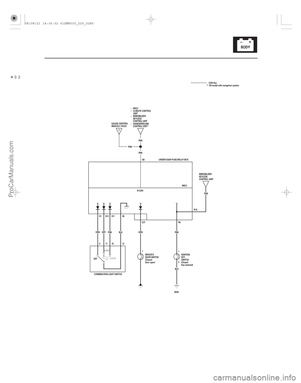
�����
22-283
R16
PNK
Q6
PNK
PNK
B-CAN PNK
R6
G504 BLK
2 1
PNK
GRN E37 MICU
UNDER-DASH FUSE/RELAY BOX
9 S1
ORN S5
S11S13
BLK
PNK
GRY
12
(
()
1011
)
OFF
COMBINATION LIGHT SWITCH DRIVER’S
DOOR SWITCH
(Closed :
Door open)
IGNITION
KEY
SWITCH
(Closed :
Key inserted)IMMOBILIZER-
KEYLESS
CONTROL UNIT
GAUGE CONTROL
MODULE (TACH)
MICU
CLIMATE CONTROL
UNIT
IMMOBILIZER-
KEYLESS
CONTROL UNIT
HANDSFREELINK
CONTROL UNIT*
1 : CAN line
*: ’09 model with navigation system
A
08/08/21 14:36:02 61SNR030_220_0285
ProCarManuals.com
DYNOMITE -2009-
Page 2264 of 2893
����
������(�#�'���������������������������������������)����
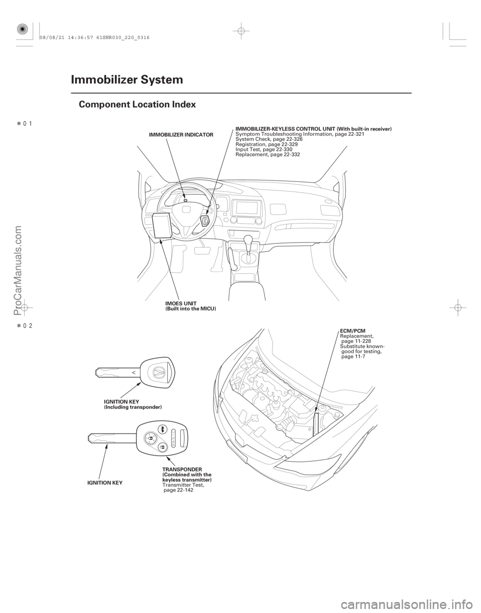
22-314Immobilizer System
Component Location Index
IMMOBILIZER INDICATOR
IMMOBILIZER-KEYLESS CONTROL UNIT (With built-in receiver)
IMOES UNIT
(Built into the MICU)
TRANSPONDER
(Combined with the
keyless transmitter)
IGNITION KEY IGNITION KEY
(Including transponder)
ECM/PCM
Symptom Troubleshooting Information, page 22-321
System Check, page 22-326
Registration, page 22-329
Input Test, page 22-330
Replacement, page 22-332
Transmitter Test, page 22-142 Replacement,
page 11-228
Substitute known- good for testing,
page 11-7
08/08/21 14:36:57 61SNR030_220_0316
ProCarManuals.com
DYNOMITE -2009-
Page 2265 of 2893
����
22-315
System Description
Mechanical key
(Including transponder) Immobilizer key
MICU
(Imoes circuit) Mechanical key
Steering lock assembly Immob")
���
�(�#�'���������������������������������������)����
22-315
System Description
Mechanical key
(Including transponder) Immobilizer key
MICU
(Imoes circuit) Mechanical key
Steering lock assembly Immobilizer-keyless
control unit
ECM/PCMTransmitter
(Including
transponder)
The vehicle is equipped with a type VI immobilizer system that will disable the vehicle unless a programmed ignition
key is used.
This system consists of a transponder combined with a keyless transmitter, immob
ilizer-keyless control unit, the MICU
(has built-in imoes unit), immobilizer indicator, and the ECM/PCM.
When the immobilizer key (programmed by the HDS) is inserted into the ignition switch and turned to ON (II), the
immobilizer-keyless control unit sends power to the trans ponder in the ignition key. The transponder then sends a
coded signal back to the immobilizer-keyless control unit which then sends a coded signal to the ECM/PCM and the
MICU (imoes unit). The ECM/PCM and MICU (imoes unit) identify this code signal, then fuel power is supplied.
NOTE: The transmitter is automatically programmed to the vehicle when a transponder is programmed by the HDS.
If the wrong key has been used or the code was not received or recognized by the unit, the indicator will come on for
about 2 seconds, then it will blink until the ignition switch is turned to LOCK (0). When the ignition switch is turned to
LOCK (0), the indicator will blink ten times to signal that the unit has reset correctly, then the indicator will go off.
08/08/21 14:36:58 61SNR030_220_0317
ProCarManuals.com
DYNOMITE -2009-
Page 2266 of 2893
����
�µ
�µ
�µ
22-316Immobilizer System
Circuit Diagram
LT GRN
PNK R9
F8 LT GRN
28
21
PNK
F24 G2D2
Q1
R12
PNK R6 R16 PNK
BRN/YEL C40
BRN/YEL LG1")
����
�(�#�'���������������������������������������)����
�µ
�µ
�µ
22-316Immobilizer System
Circuit Diagram
LT GRN
PNK R9
F8 LT GRN
28
21
PNK
F24 G2D2
Q1
R12
PNK R6 R16 PNK
BRN/YEL C40
BRN/YEL LG1
LG2
BRN/YEL C44 B-CAN
Q6
G504 BLK
2 1
BRN/YEL IG1
2
YEL MICU
B-CAN
VBU
K-LINE
IGKEYSW
LG
7
BLK
BRN
IG1 C36
BLK/GRN
5
LT BLU
WHT
A44
B1
B36 PG2
PG1
BLK
G101 PNK
BRN
PNK
1
No. 2 (15 A)
WHT
KEY
IMOCD
ECM/PCM UNDER-DASH FUSE/RELAY BOX
ORN IG1
BAT
BLU
No. 23 (10 A)
UNDER-HOOD FUSE/RELAY BOX
No. 2 (IG) (50 A)
BATTERY IGNITION SWITCH
No. 1 (BAT) (100 A)
IMMOBILIZER-KEYLESS CONTROL UNIT6
3 4
PGM-FI
MAIN RELAY 2
(FUEL PUMP)
DATA LINK
CONNECTOR
IGNITION
KEY SWITCH
(Closed: Key inserted)
IG1 HOT in ON (II)
and START (III)
GAUGE CONTROL
MODULE (TACH)
UNDER-DASH
FUSE/RELAY BOX IMMOBILIZER
INDICATOR
(LED)
PARKING
BRAKE
SWITCH
(Closed:
Lever pulled)
UNDER-DASH
FUSE/RELAY
BOX
D4
H1
1: CAN line
: Other communication line
*1: ’06 07 models
*2: ’07 09 models
*3: ’08 09 models
ORN
IMOES UNIT
(Built into the MICU) MICU
BLK*2
IMOCD
BLK/RED*1 BLK*3
08/08/21 14:36:58 61SNR030_220_0318
ProCarManuals.com
DYNOMITE -2009-