Page 2062 of 2893

Panic Mode
Keyless Entry System
22-115
The panic mode sounds the alarm in order to attract attention. When the PANIC button on the transmitter is pressed
and held for 2 seconds, the horn sounds and the exterior lights flash for about 20 seconds.
The panic mode can be cancelled at anytime by pressing any button on the transmitter or by turning the ignition
switch to ON (II). The panic mode will not function if the ignition switch is to ON (II).
The keyless entry system is integrated with the multiplex integrated control system. The multiplex integrated control
unit (MICU) receives LOCK, UNLOCK and PANIC signals from the immobilizer-keyless control unit (keyless receiver).
The keyless entry system allows you to lock and unlock the vehicle with the transmitter.
When the switch for the ceiling light is in the center (DOOR) position, it will come on when the UNLOCK button is
pressed. If a door is not opened, the light will go off in about 30 seconds, and the doors will relock. If the doors are
locked with the transmitter within 30 seconds, the light will go off immediately.
08/08/21 14:25:09 61SNR030_220_0117
ProCarManuals.com
DYNOMITE -2009-
Page 2064 of 2893
�����
22-117
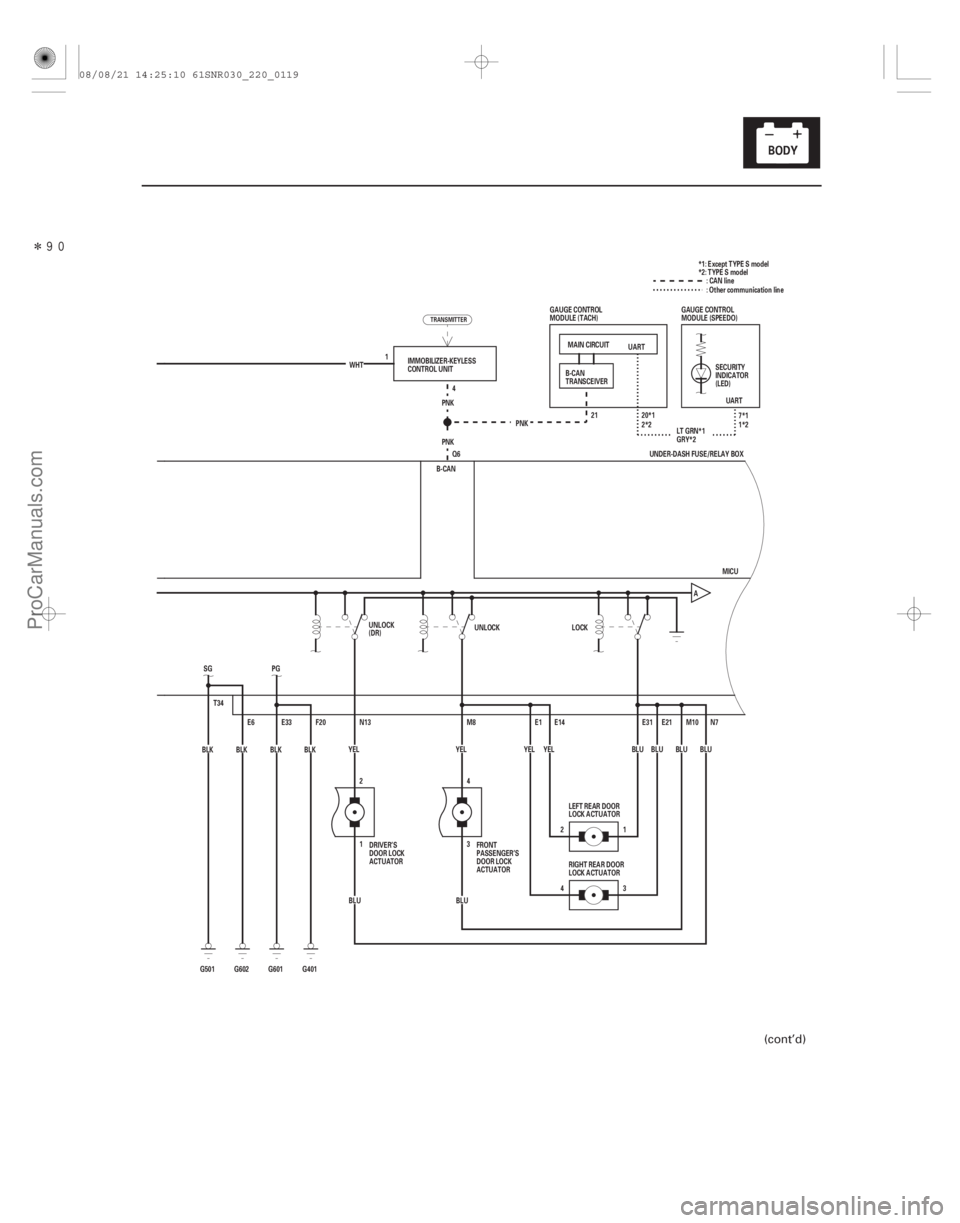
UART
UART
MAIN CIRCUIT
PNK PNK 20*1
21
LT GRN*1
T34 E6
G501 BLK
SG
BLK
G602 PG
F20
E33
G601 BLK BLK
G401 YEL
BLU
BLU
BLU
B-CAN
M10
E21E31
BLU
E1 E14
YEL
43 1
2 N7
YEL M8
4
BLU 3
N13
1
BLU 2
YEL A
MICU
1
Q6 4
PNK
WHT
IMMOBILIZER-KEYLESS
CONTROL UNIT
DRIVER’S
DOOR LOCK
ACTUATOR FRONT
PASSENGER’S
DOOR LOCK
ACTUATORLEFT REAR DOOR
LOCK ACTUATOR
RIGHT REAR DOOR
LOCK ACTUATOR SECURITY
INDICATOR
(LED)
B-CAN
TRANSCEIVER
GAUGE CONTROL
MODULE (TACH)
GAUGE CONTROL
MODULE (SPEEDO):CANline
2*2 7*1
1*2
GRY*2 *1: Except TYPE S model
*2: TYPE S model
: Other communication line
UNDER-DASH FUSE/RELAY BOX
UNLOCK
(DR) UNLOCK
LOCK
TRANSMITTER
(cont’d)
08/08/21 14:25:10 61SNR030_220_0119
ProCarManuals.com
DYNOMITE -2009-
Page 2065 of 2893
����
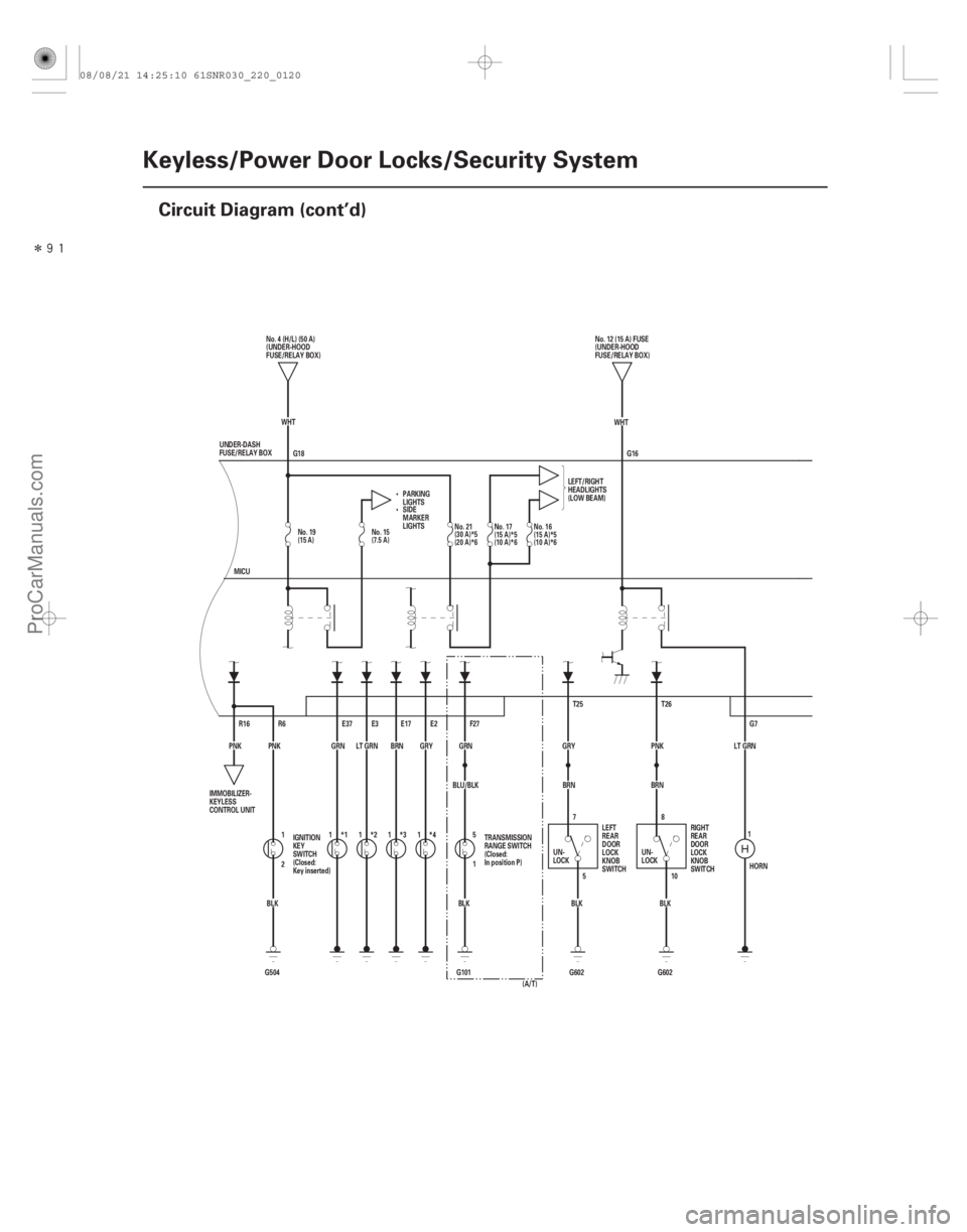
22-118Keyless/Power Door Locks/Security System
Circuit Diagram (cont’d)
G18
HORN
LT GRN
G7
G16
T26
PNK
BRN
G602BLK8
10
5
7
BLK
G602
BRN
GRY T25
BLU/BLK GRN
F27
5
1
BLK
G101
E2
GRY
*4
E17
BRN
*3
E3
LT GRN
*2
*1
GRN
E37
G504 BLK
2 1
PNK
R6
PNK R16 WHT
WHT
MICU No. 4 (H/L) (50 A)
(UNDER-HOOD
FUSE/RELAY BOX)
PARKING
LIGHTS LEFT/RIGHT
HEADLIGHTS
(LOW BEAM)
UNDER-DASH
FUSE/RELAY BOX No. 12 (15 A) FUSE
(UNDER-HOOD
FUSE/RELAY BOX)
IMMOBILIZER-
KEYLESS
CONTROL UNIT IGNITION
KEY
SWITCH
(Closed:
Key inserted) TRANSMISSION
RANGE SWITCH
(Closed:
In position P)
UN-
LOCKLEFT
REAR
DOOR
LOCK
KNOB
SWITCH RIGHT
REAR
DOOR
LOCK
KNOB
SWITCH
UN-
LOCK
SIDE
MARKER
LIGHTS
(A/T)
1111
1
No. 19
(15 A)No. 15
(7.5 A) No. 21
(30 A)*5
(20 A)*6No. 17
(15 A)*5
(10 A)*6No. 16
(15 A)*5
(10 A)*6
08/08/21 14:25:10 61SNR030_220_0120
ProCarManuals.com
DYNOMITE -2009-
Page 2074 of 2893
����
�µ
�µ
�µ
�µ �µ
�µ
�µ
�µ
Keyless operation does not work (LOCK,
UNLOCK, PANIC)
YES
NO
YES
NO YES
NO
YES
NO
22-127
IMMOBILIZER-KEYLES")
���
����
�(�#�'���������������������������������������)����
�µ
�µ
�µ
�µ �µ
�µ
�µ
�µ
Keyless operation does not work (LOCK,
UNLOCK, PANIC)
YES
NO
YES
NO YES
NO
YES
NO
22-127
IMMOBILIZER-KEYLESS CONTROL UNIT 7P CONNECTOR
VBU (WHT)
IGNITION KEY SWITCH 6P CONNECTOR GND
IG KEY SW
NOTE:
Before troubleshooting, check the B-CAN DTCs. If any DTC is indicated, troubleshoot the indicated DTC first.
Before troubleshooting, do the keyless transmitter test (see page 22-142).
1. Turn the ignition switch to ON (II).
2. Try to start the engine.
ThesystemisOK,gotostep3.
Go to the immobilizer symptom
troubleshooting (see page 22- 323).
3. Turn the ignition switch to LOCK (0).
4. Connect the HDS to the data link connector.
5. Close all doors, then turn the ignition switch to ON (II).
6. Enter the BODY ELECTRICAL menu, and check the door switch parameters.
Go to step 7.
Faulty door switch, or shorted door switch
wire. Repair as necessary.
7. Remove the ignition key from the ignition switch.
8. Disconnect the immobilizer-keyless control unit 7P connector. 9. Measure the voltage between immobilizer-keyless
control unit 7P connector terminal No. 1 and body
ground.
Go to step 10.
Check the fuse No. 23 (10 A) in the under-
hood fuse/relay box. If the fuse is blown, replace
the fuse and repair a short to ground in the wire. If
the fuse is OK, repair an open in the wire.
10. Disconnect the ignition key switch 6P connector.
11. At the ignition key switch side, check for continuity between ignition key switch 6P connector terminals
No. 1 and No. 2.
Faulty ignition key switch or short to ground,
replace the steering lock assembly (see page 17-14).
Go to step 12. (cont’d)
Wire side of female terminals
Terminal side of male terminals
Doestheenginestart? Do al l d oor sw i t ches i nd i cat e OF F ? Is there battery voltage?
Is there continuity?
08/08/21 14:26:03 61SNR030_220_0129
ProCarManuals.com
DYNOMITE -2009-
Page 2075 of 2893

IGNITION KEY SWITCH 6P CONNECTOR
GND
IG KEY SW
IGNITION KEY")
����
��������
�µ
�µ
�µ
�µ �µ
�µ
YES
NO
YES
NO YES
NO
22-128Keyless/Power Door Locks/Security System
Symptom Troubleshooting (cont’d)
IGNITION KEY SWITCH 6P CONNECTOR
GND
IG KEY SW
IGNITION KEY SWITCH 6P CONNECTOR
IMMOBILIZER-KEYLESS CONTROL UNIT 7P CONNECTOR IG KEY SW (PNK)
IG KEY SW (PNK) IMMOBILIZER-KEYLESS CONTROL UNIT 7P CONNECTOR
IG KEY SW (PNK)
12. Insert the ignition key into the ignition switch.
13. At the ignition key switch side, check for continuitybetween ignition key switch 6P connector terminals
No. 1 and No. 2.
Go to step 14.
Faulty ignition key switch, replace the
steering lock assembly (see page 17-14).
14. Check for continuity between immobilizer-keyless control unit 7P connector terminal No. 6 and
ignition key switch 6P connector terminal No. 1.
Go to step 15.
Repair an open in the wire. 15. Check for continuity between immobilizer-keyless
control unit 7P connector terminal No. 6 and body
ground.
Repair a short to ground in the wire.
Replace the immobilizer-keyless control unit
(see page 22-332).
Terminal side of male terminals
Wire side of female terminalsWire side of female terminals Wire side of female terminals
Is there continuity?
Is there continuity? Is there continuity?
08/08/21 14:26:04 61SNR030_220_0130
ProCarManuals.com
DYNOMITE -2009-
Page 2091 of 2893

����
Without HDS
22-143
7. Use a different known-good keyless transmitterand repeat steps 3 and 4.
NOTE: The keyless transmitter does not need to be
programmed to the vehicle for this test.
If (DIFFERENT) KEYLESS ENTRY TRANSMITTER CODE IS RECEIVED is indicated, replace the
keyless transmitter and do the immobilizer
system registration (see page 22-329).
If KEYLESS ENTRY TRANSMITTER CODE IS NOT RECEIVED is indicated, the immobilizer-keyless
control unit is faulty, replace it and do the
immobilizer system registration (see page
22-329).
NOTE: As the keyless transmitter is combined with
the immobilizer transponder, when the
transponder is registered by the HDS, the keyless
transmitter programming is completed
automatically. 1. Start the engine.
If the engine does not start, go to the immobilizersymptom troubleshooting (see page 22-323).
If the engine starts, go to step 2.
2. Press the lock or unlock button five or six times to reset the transmitter.
If the locks work, the transmitter is OK.
If the locks don’t work, go to step 3.
3. Open the transmitter and check for water damage. If you find any water damage, replace thetransmitter.
If there is no water damage, go to step 4.
(cont’d)
08/08/21 14:26:07 61SNR030_220_0145
ProCarManuals.com
DYNOMITE -2009-
Page 2092 of 2893
����
22-144Keyless/Power Door Locks/Security System
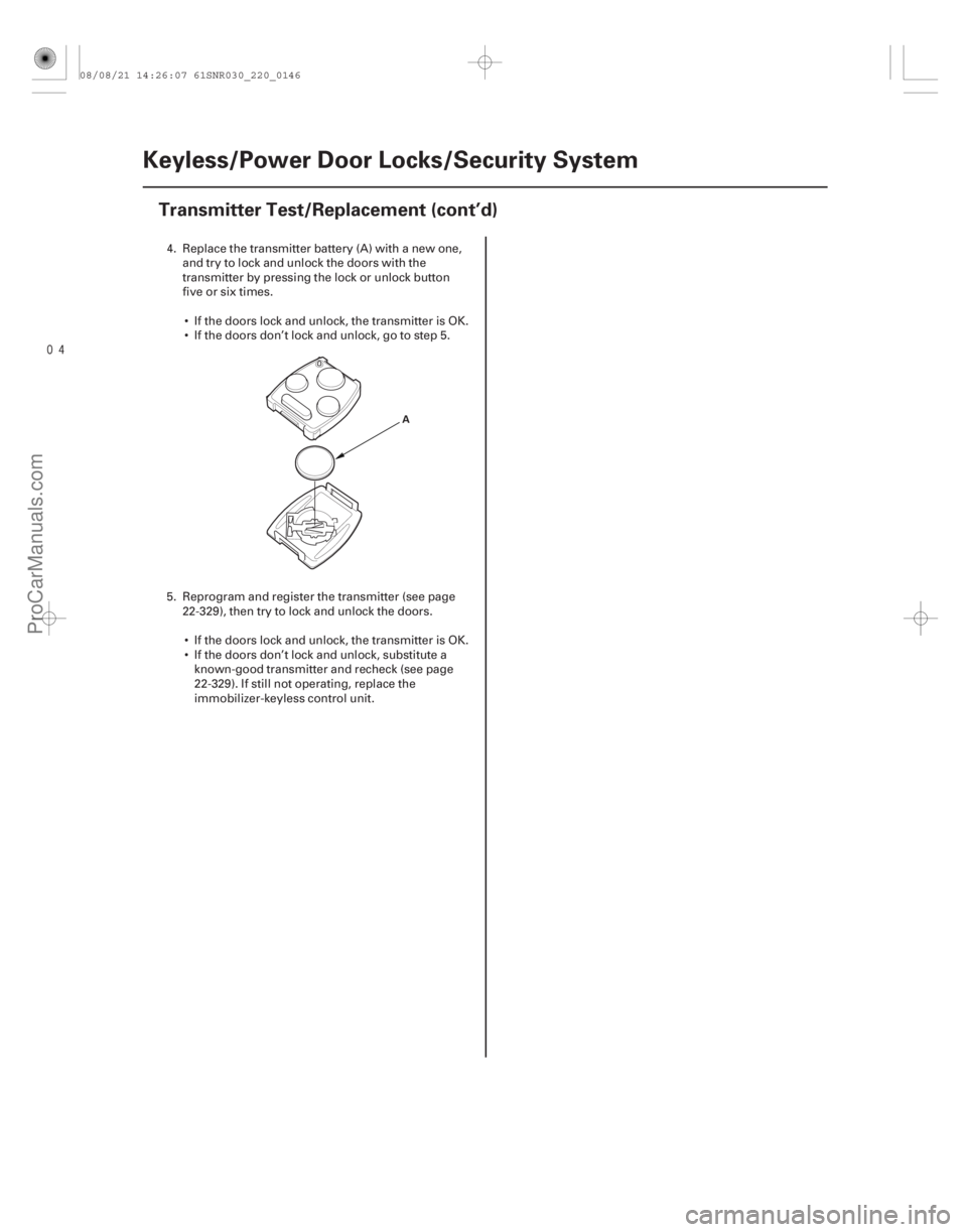
Transmitter Test/Replacement (cont’d)
A
4. Replace the transmitter battery (A) with a new one,
and try to lock and unlock the doors with the
transmitter by pressing the lock or unlock button
five or six times.
If the doors lock and unlock, the transmitter is OK.
If the doors don’t lock and unlock, go to step 5.
5. Reprogram and register the transmitter (see page 22-329), then try to lock and unlock the doors.
If the doors lock and unlock, the transmitter is OK.
If the doors don’t lock and unlock, substitute a known-good transmitter and recheck (see page
22-329). If still not operating, replace the
immobilizer-keyless control unit.
08/08/21 14:26:07 61SNR030_220_0146
ProCarManuals.com
DYNOMITE -2009-
Page 2153 of 2893
����
�µ
�µ
22-203
Circuit Diagram
5 6
R13
ORN
LT BLU
BLK5
7
G501 LOCK
WHT
T23
BRN T24
LT GRN
6
4
UNDER-DASH FUSE/RELAY BOX 7*2
1*1 8*1
9*2K5
G3 D")
����
�(�#�'���������������������������������������)����
�µ
�µ
22-203
Circuit Diagram
5 6
R13
ORN
LT BLU
BLK5
7
G501 LOCK
WHT
T23
BRN T24
LT GRN
6
4
UNDER-DASH FUSE/RELAY BOX 7*2
1*1 8*1
9*2K5
G3 D2
PG
SG
PNKR16
G501 BLK
T34
BLK
G401 F20
E2
GRY
LT BLU LT BLU
CEILING LIGHT BLU
PNK FRONT
INDIVIDUAL
MAP LIGHTS
PNKDOOR
IG1Q6
B-CAN
No. 22 (7.5 A)
No. 2 (IG) (50 A)
No. 1 (BAT) (100 A)
OFFUNDER-DASH FUSE/RELAY BOX
(7.5 A) No. 10
PNK
PNK RED
BLU
BRN E17
E33 R6
G601 BLK
E6
BLK
G602 K4
MICU
E3
E37
GRN LT GRN
G504BLKPNK
1
2
WHT
IG1
BAT
UNDER-HOOD FUSE/RELAY BOX
BATTERY IGNITION SWITCH
IG1 HOT in ON (II)
and START (III)
INTERIOR
LIGHT
SWITCH IMMOBILIZER-
KEYLESS CONTROL
UNIT
DRIVER’S
DOOR
SWITCH
(Closed:
Door open) FRONT
PASSENGER’S
DOOR SWITCH
(Closed:
Door open) LEFT
REAR DOOR
SWITCH
(Closed:
Door open)RIGHT
REAR DOOR
SWITCH
(Closed:
Door open) IGNITION
KEY
SWITCH
(Closed:
Key inserted)IMMOBILIZER-
KEYLESS
CONTROL
UNIT
DRIVER’S
DOOR
LOCK
KNOB
SWITCH
UN-
LOCK
IGNITION
KEY LIGHT
(LED)
H1
D2
1 111 :CANline
*1: ’06 07 models
*2: ’08 09 models
TRANSMITTER
08/08/21 14:27:54 61SNR030_220_0205
ProCarManuals.com
DYNOMITE -2009-