Page 1432 of 2893
���� Special Tools Required
Removal/Installation
18-2218-22 Front Suspension
Lower Ball Joint Replacement
(cont’d)
Lower Arm Removal/Installation
A")
���
�(�#�'�������������������������������
� �����)���� Special Tools Required
Removal/Installation
18-2218-22 Front Suspension
Lower Ball Joint Replacement
(cont’d)
Lower Arm Removal/Installation
A
10x1.25mm
34 N·m
(3.5 kgf·m,
25 lbf·ft)
B C
D
7. Install the lower ball joint in the reverse order of removal, and note these items:
First install all of the components, and lightly tighten the bolts and the nuts, then raise the
suspension to load it with the vehicle’s weight
before fully tightening to the specified torque
values.
Be careful not to damage the ball joint boot when connecting the knuckle.
Before connecting the lower ball joint to the knuckle, degrease the threaded section and the
tapered portion of the ball joint pin, the ball joint
connecting hole, the threaded section, and the
mating surfaces of the castle nut.
Torque the castle nut to the lower torque specification, then tighten it only far enough to
align the slot with the ball joint pin hole. Do not
align the castle nut by loosening it.
Use a new spindle nut during reassembly.
Before installing the wheel, clean the mating surfaces of the brake disc and the inside of the
wheel.
8. Check the wheel alignment, and adjust it if necessary (see page 18-5). Bushing driver 07AAF-SVAA100
Receiver set 07AAF-SVAA200
1. Raise the front of the vehicle, and support it with safety stands in the proper locations (see page
1-11).
2. Remove the front wheels.
3. Remove the flange nut (A) while holding the joint pin (B) with a hex wrench (C), then disconnect both
sides of the stabilizer link from the lower arm (D).
NOTE: Use the new flange nut during reassembly.
4. Turn the stabilizer bar backward to gain easier access to the front side of the lower arm mounting
bolt.
Replace.
08/08/21 14:57:35 61SNR030_180_0022
ProCarManuals.com
DYNOMITE -2009-
Page 1433 of 2893

C
12x1.25mm
59N·m(6.0kgf·m,43lbf·ft) A
D
12x1.25mm
59 N·m (6.0 kgf·m, 43 lbf·ft) E D
C
B
12x1.25mm
64 N·m
(6.5 kgf·m, 47 lbf·ft)
A")
���
����
18-23
B
12x1.25mm
59 N·m (6.0 kgf·m, 43 lbf·ft)
C
12x1.25mm
59N·m(6.0kgf·m,43lbf·ft) A
D
12x1.25mm
59 N·m (6.0 kgf·m, 43 lbf·ft) E D
C
B
12x1.25mm
64 N·m
(6.5 kgf·m, 47 lbf·ft)
A
14x1.5mm
83 N·m
(8.5 kgf·m, 61 lbf·ft)
5. Remove the flange bolt and the self-locking nuts
from the lower arm (A).
NOTE: During installation, install the new flange
bolt and the new self-locking nuts. After lightly
tightening all three fasteners, tighten them to the
specified torque in the following order, the nut on
the front (B), the nut on the rear (C), then the bolt
(D).
6. Disconnect the lower ball joint (E) from the lower arm. 7. Remove the front side of the lower arm mounting
bolt (A).
NOTE: Use the new mounting bolt during
reassembly.
8. Remove the rear side of the lower arm mounting bolt (B), then remove the lower arm (C) from the
front suspension subframe (D).
NOTE: Use the new mounting bolt during
reassembly.
9. Install the lower arm in the reverse order of removal, and note these items:
First install all of the components, and lightly tighten the bolts and the nuts, then raise the
suspension to load it with the vehicle’s weight
before fully tightening to the specified torque
values.
Before installing the wheel, clean the mating surfaces of the brake disc and the inside of the
wheel.
10. Check the wheel alignment, and adjust it if necessary (see page 18-5).
(cont’d)
Replace.
Replace.
Replace. Replace.
Replace.
08/08/21 14:57:36 61SNR030_180_0023
ProCarManuals.com
DYNOMITE -2009-
Page 1434 of 2893

A
B
Press
07AAF-SVAA100
07AAF-SVAA200
(Attachment A) B
A
Press
07AAF-SVAA100
07AAF-SVAA200
(A")
����
��������
����
�
Bushing Replacement
18-24Front Suspension
Lower Arm Removal/Installation (cont’d)
A
B
Press
07AAF-SVAA100
07AAF-SVAA200
(Attachment A) B
A
Press
07AAF-SVAA100
07AAF-SVAA200
(Attachment B)
B
07AAF-SVAA200
(Attachment A)
C
21°20’ 3°
A
FRONT
A
B
CNOTE: Replace the lower arm (A) as an assembly if the
lower arm has the paint mark (B) around the hole near
the front bushing. The paint mark can also be seen
around a hole on the bottom side of the lower arm in
the same area. Paint marks indicate a oversize bushing
has been installed.
1. Press out the bushing (A) with the bushing driver, receiver set (attachment A), and a hydraulic press,
and remove the bushing from the lower arm (B).
NOTE: Be careful not to damage the inside of the
bushing hole when pressing on the bushing.
2. Clean the mating surfaces of the new bushing and the lower arm. 3. Position the tab (A) of the bushing (B) with the
lower arm (C) as shown.
4. Using a hydraulic press, bushing driver, and receiver set (attachments A and B), press in the
bushing into the lower arm.
5. Using a yellow oil-based paint marker, paint a mark (A) around the hole (B) near the front bushing (C).
Also paint a mark around the hole on the bottom
side of the lower arm in the same area.
NOTE: These marks are used to identify a lower
arm that has had the bushing replaced. Do not
replace the bushing in a lower arm with there paint
marks; you must replace the lower arm.
08/08/21 14:57:37 61SNR030_180_0024
ProCarManuals.com
DYNOMITE -2009-
Page 1436 of 2893
����
Removal
18-26 Front Suspension
Damper/Spring Removal and Installation
A
B
8x1.25mm
A
14x1.5mm
B A
B
C
10x1.25mm
A
1. Turn the igni")
����
���
����
����
�(�#�'�����������������������
���
���
� �����)����
Removal
18-26 Front Suspension
Damper/Spring Removal and Installation
A
B
8x1.25mm
A
14x1.5mm
B A
B
C
10x1.25mm
A
1. Turn the ignition switch to ON (II), then turn on thewindshield wipers. Turn the ignition switch to
LOCK (0) when the wipers are near the A-pillars.
2. Raise the front of the vehicle, and support it with safety stands in the proper locations (see page
1-11).
3. Remove the front wheel.
4. Remove the wheel speed sensor harness clip (A) and the brake hose bracket (B) from the damper. Do
not disconnect the wheel speed sensor connector.
5. Remove the damper pinch bolts (A) and the self- locking nuts (B) from the damper.
NOTE: Do not allow the knuckle to rotate too far
outward. This may allow the driveshaft inboard
joint come apart. 6. Remove the service cap (A) and the lid (B).
7. Remove the three flange nuts (C) from top of the
damper.
8. Remove the damper/spring (A). NOTE: The left and right damper springs are different. Mark the springs L and R before you continue.
Be careful not to damage the body.
Replace.
Replace. Replace.
08/08/21 14:57:38 61SNR030_180_0026
ProCarManuals.com
DYNOMITE -2009-
Page 1437 of 2893

’06-08 models type S model:
10x1.25mm
59N·m(6.0kgf·m,43lbf·ft)
�")
�
��
����
����
�
��
Installation
18-27
FRONT
A
B
C
A
’06-08 models except Type S model:
10x1.25mm
44N·m(4.5kgf·m,33lbf·ft)
’06-08 models type S model:
10x1.25mm
59N·m(6.0kgf·m,43lbf·ft)
’09 model:
10x1.25mm
59N·m(6.0kgf·m,43lbf·ft)
A
14x1.5mm
90 N·m
(9.2 kgf·m,
67 lbf·ft)
C
B
A
B
C
8x1.25mm
22 N·m
(2.2 kgf·m, 16 lbf·ft)1. Install the damper/spring (A) onto the frame. Note
the direction of the damper mounting base as
shown.
NOTE: Be careful not to damage the body.
2. Loosely install the new flange nuts (A). NOTE: Install the service cap (B) and the lid (C) after
tightening the flange nuts to the specified torque
value. 3. Loosely install the new damper pinch bolts (A) and
the new self-locking nuts (B) to the damper (C).
4. Raise the front suspension with a floor jack to load the suspension with the vehicle’s weight.
5. Tighten the flange nuts on top of the damper to the specified torque value.
6. Tighten the damper pinch bolts to the specified torque value.
7. Install the wheel speed sensor harness clip (A) and the brake hose bracket (B) to the damper (C).
8. Install the service cap and the lid.
9. Clean the mating surfaces of the brake disc and the inside of the wheel, then install the front wheel.
10. Check the wheel alignment, and adjust it if necessary (see page 18-5).
11. Turn the ignition switch to ON (II), then turn the windshield wipers to the default positions, and turn
the ignition switch to LOCK (0).
Replace.
Replace.
Replace.
Replace.
Replace.
08/08/21 14:57:39 61SNR030_180_0027
ProCarManuals.com
DYNOMITE -2009-
Page 1438 of 2893
����
�(�#�'�����������������������
���
���
�"�����)����
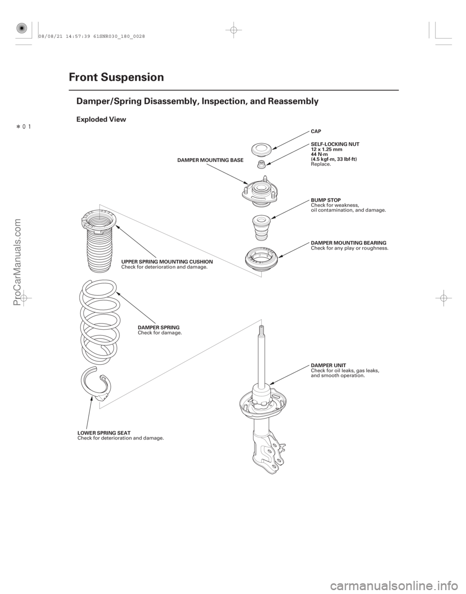
Exploded View
18-28Front Suspension
Damper/Spring Disassembly, Inspection, and Reassembly
DAMPER MOUNTING BEARING
BUMP STOP
DAMPER UNIT CAP
SELF-LOCKING NUT
12x1.25mm
44 N·m
(4.5 kgf·m, 33 lbf·ft)
UPPER SPRING MOUNTING CUSHION DAMPER SPRING DAMPER MOUNTING BASE
LOWER SPRING SEAT Check for any play or roughness.
Check for weakness,
oil contamination, and damage.
Check for oil leaks, gas leaks,
andsmoothoperation. Replace.
Check for deterioration and damage. Check for damage.
Check for deterioration and damage.
08/08/21 14:57:39 61SNR030_180_0028
ProCarManuals.com
DYNOMITE -2009-
Page 1440 of 2893

A
B
C
D
A B
C FRONT
FRONT
44 °24 ’ 3 °
A C
B
D
C
A
Left
Right
A
12")
�Ú
����
�
�� �����
����
�
Reassembly
18-30Front Suspension
Damper/Spring Disassembly, Inspection, and Reassembly (cont’d)
A
B
C
D
A B
C FRONT
FRONT
44 °24 ’ 3 °
A C
B
D
C
A
Left
Right
A
12 x 1.25 mm
44 N·m (4.5 kgf·m, 33 lbf·ft)
C
07AAA-SVAA100
B
1. Install the damper spring (A) on the upper springmounting cushion (B) by aligning the upper end (C)
of the damper spring with the ledge portion (D) of
the upper spring mounting cushion.
2. Compress the damper spring.
3. Install all the parts except the self-locking nut and the cap onto the damper unit (A) by referring to the
Exploded View.
4. Align the bottom of the spring (B) and the stepped part of the lower spring seat (C) on the damper unit. 5. Align the damper bracket (A) and the damper
mounting base (B) so that the ‘‘ ’’ stamp (C) points
toward the front.
6. Align the angle of the stud bolt (D) on the damper bracket as shown.
7. Install the new self-locking nut (A).
8. Hold the damper shaft using a hex wrench (B), and tighten the self-locking nut using the strut nut
adapter (C) and a torque wrench to the specified
torque value.
9. Remove the damper/spring from the strut spring compressor.
10. Install the cap.
Replace.
08/08/21 14:57:40 61SNR030_180_0030
ProCarManuals.com
DYNOMITE -2009-
Page 1441 of 2893
����
�(�#�'���������������
���������������
� �����)����
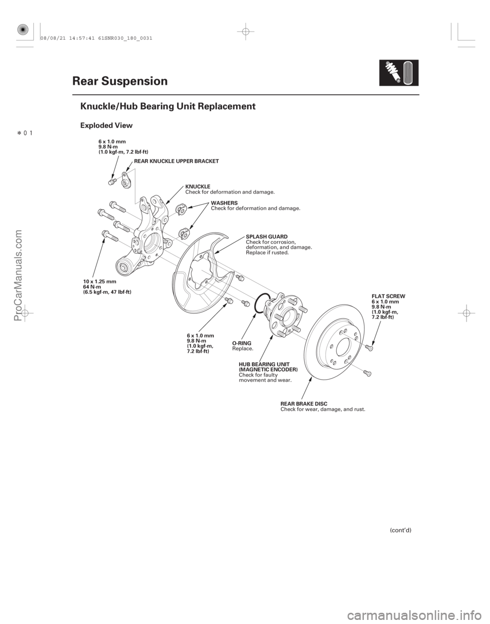
Exploded View
18-31
Rear Suspension
Knuckle/Hub Bearing Unit Replacement
KNUCKLE
6x1.0mm
9.8 N·m
(1.0 kgf·m, 7.2 lbf·ft)
WASHERS
10x1.25mm
64 N·m
(6.5 kgf·m, 47 lbf·ft) O-RINGFLAT SCREW
6x1.0mm
9.8 N·m
(1.0 kgf·m,
7.2 lbf·ft)
HUB BEARING UNIT
(MAGNETIC ENCODER) REAR BRAKE DISC
SPLASH GUARD
6x1.0mm
9.8 N·m
(1.0 kgf·m,
7.2 lbf·ft)
REAR KNUCKLE UPPER BRACKET
(cont’d)
Check for deformation and damage.
Check for deformation and damage.
Replace.Check for faulty
movement and wear.
Check for wear, damage, and rust.
Check for corrosion,
deformation, and damage.
Replace if rusted.
08/08/21 14:57:41 61SNR030_180_0031
ProCarManuals.com
DYNOMITE -2009-