Page 639 of 2893
����
�(�#�'���������������������������������������)����
11-311
Fuel Supply System
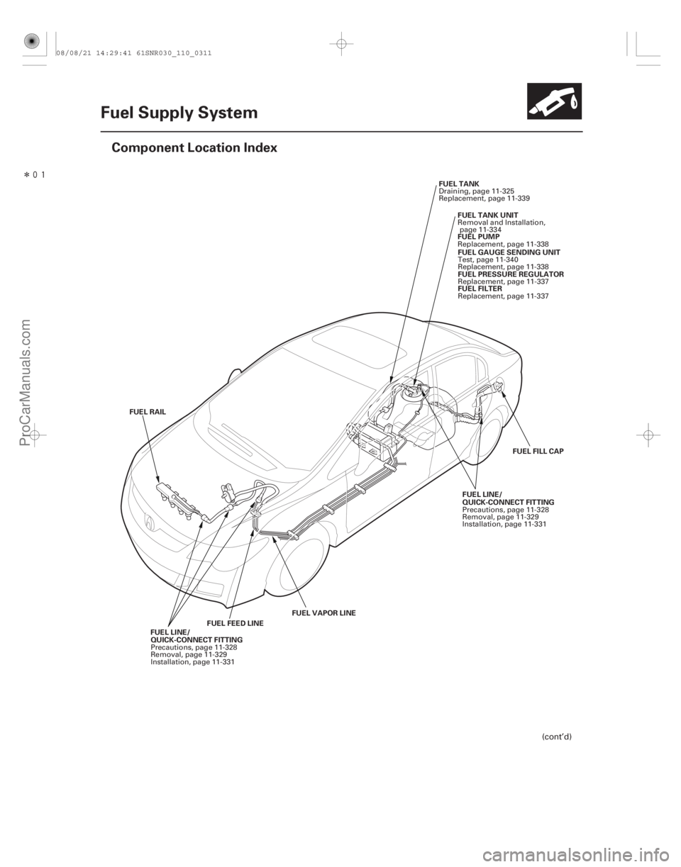
Component Location Index
FUEL FEED LINE
FUEL VAPOR LINE
FUEL RAIL
QUICK-CONNECT FITTING QUICK-CONNECT FITTING
FUEL FILL CAP
FUEL TANK
FUEL PUMPFUEL GAUGE SENDING UNIT
FUEL PRESSURE REGULATOR
FUEL FILTER
FUEL TANK UNIT
FUEL LINE/
FUEL LINE/
(cont’d)
Precautions, page 11-328
Removal, page 11-329
Installation, page 11-331 Precautions, page 11-328
Removal, page 11-329
Installation, page 11-331
Draining, page 11-325
Replacement, page 11-339
Replacement, page 11-338Test, page 11-340
Replacement, page 11-338Replacement, page 11-337
Replacement, page 11-337
Removal and Installation,
page 11-334
08/08/21 14:29:41 61SNR030_110_0311
ProCarManuals.com
DYNOMITE -2009-
Page 640 of 2893
�����
�����
11-312Fuel Supply System
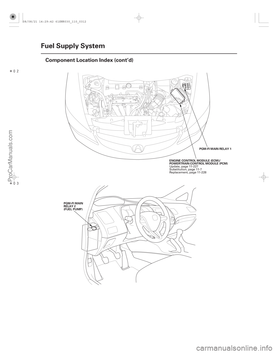
Component Location Index (cont’d)
PGM-FI MAIN RELAY 1
ENGINE CONTROL MODULE (ECM)/
POWERTRAIN CONTROL MODULE (PCM)
PGM-FI MAIN
RELAY 2
(FUEL PUMP) Update, page 11-227
Substitution, page 11-7
Replacement, page 11-228
08/08/21 14:29:42 61SNR030_110_0312
ProCarManuals.com
DYNOMITE -2009-
Page 646 of 2893
���� �µ
�µ
YES
NO
11-318 Fuel Supply System
Fuel Pump Circuit Troubleshooting
A
PGM-FI MAIN RELAY 2 (FUEL PUMP) 4P CONNECTOR IGP U")
����
���
����
����
�(�#�'���������������������������������������)���� �µ
�µ
YES
NO
11-318 Fuel Supply System
Fuel Pump Circuit Troubleshooting
A
PGM-FI MAIN RELAY 2 (FUEL PUMP) 4P CONNECTOR IGP UNDER-DASH FUSE/RELAY BOX CONNECTOR G (21P)
IGP (ORN)
JUMPER WIRE
UNDER-HOOD FUSE/RELAY BOX CONNECTOR E (10P) IGP (ORN)
If you suspect a problem with the fuel pump, check that
the fuel pump actually runs; when it is on, you will hear
some noise if you listen to the fuel fill port with the fuel
fill cap removed. The fuel pump should run for
2 seconds when the ignition switch is first turned on. If
the fuel pump does not make noise, check as follows:1. Turn the ignition switch to LOCK (0).
2. Remove the under-dash fuse/relay box (see page 22-66), then remove PGM-FI main relay 2 (FUEL
PUMP) (A) from the under-dash fuse/relay box.
3. Reinstall the under-dash fuse/relay box.
4. Turn the ignition switch to ON (II).
5. Measure the voltage between PGM-FI main relay 2 (FUEL PUMP) 4P connector terminal No. 4 and
body ground. Go to step 12.
Go to step 6.
6. Turn the ignition switch to LOCK (0).
7. Disconnect the under-hood fuse/relay box connector E (10P).
8. Disconnect the C101 connector at left side of engine compartment (see page 22-16).
9. Disconnect under-dash fuse/relay box connector G (21P).
10. Connect under-dash fuse/relay box connector G (21P) terminal No. 4 to body ground with a jumper
wire.
11. Check for continuity between under-hood fuse/ relay box connector E (10P) terminal No. 5 and
body ground.
Terminal side of female terminals Wire side of female terminals
Wire side of female terminals
Is there battery voltage?
08/08/21 14:29:45 61SNR030_110_0318
ProCarManuals.com
DYNOMITE -2009-
Page 647 of 2893
 4P CONNECTORIG1 PGM-FI MAIN RELAY 2 (FUEL PUMP) 4P CONNECTOR
IMOFPRJUMPER WIRE
IMOFPR (BRN)
ECM/PCM CO")
��������
����
�µ
�µ
�µ
�µ
�µ
�µ
YES
NO
YES
NO
YES
NO
11-319
PGM-FI MAIN RELAY 2 (FUEL PUMP) 4P CONNECTORIG1 PGM-FI MAIN RELAY 2 (FUEL PUMP) 4P CONNECTOR
IMOFPRJUMPER WIRE
IMOFPR (BRN)
ECM/PCM CONNECTOR A (44P)
Replace PGM-FI main relay 1.
If needed, replace the under-hood fuse/relay box
(see page 22-65).
Repair open in the wire between the under-
hood fuse/relay box and the under-dash fuse/relay
box.
12. Measure the voltage between PGM-FI main relay 2 (FUEL PUMP) 4P connector terminal No. 1 and
body ground.
Go to step 13.
ChecktheNo.2FUELPUMP(15A)fuseinthe under-dash fuse/relay box.
If needed, replace the under-dash fuse/relay box (see page 22-66).
13. Turn the ignition switch to LOCK (0). 14. Connect PGM-FI main relay 2 (FUEL PUMP) 4P
connector terminal No. 3 to body ground with a
jumper wire.
15. Jump the SCS line with the HDS.
16. Disconnect ECM/PCM connector A (44P).
17. Check for continuity between body ground and ECM/PCM connector terminal A15.
Go to step 18.
Repair open in the wire between PGM-FI main
relay 2 (FUEL PUMP) and the ECM/PCM (A15).
18. Remove the under-dash fuse/relay box (see page 22-66), then reinstall PGM-FI main relay 2 (FUEL
PUMP).
19. Reinstall the under-dash fuse/relay box (see page 22-66).
(cont’d)
Terminal side of female terminals Terminal side of female terminals
Terminal side of female terminals
Is there continuity?
Is there battery voltage? Is there continuity?
08/08/21 14:29:46 61SNR030_110_0319
ProCarManuals.com
DYNOMITE -2009-
Page 648 of 2893

MRLY (GRN)
JUMPER WIRE
ECM/PCM CONNECTOR A (44P)
IMOFPR (BRN)
ECM/")
����
�����
��
�
�
�µ
�µ �µ
�µ
�µ
�µ
YES
NO YES
NO
YES
NO
11-320Fuel Supply System
Fuel Pump Circuit Troubleshooting (cont’d)
MRLY (GRN)
JUMPER WIRE
ECM/PCM CONNECTOR A (44P)
IMOFPR (BRN)
ECM/PCM CONNECTOR A (44P)UNDER-DASH FUSE/RELAY BOX CONNECTOR F (34P)
IMOFPR (BRN)
IMOFPR (BRN)
UNDER-DASH FUSE/RELAY BOX CONNECTOR F (34P)
20. Connect ECM/PCM connector terminal A6 to body
ground with a jumper wire.
21. Turn the ignition switch to ON (II).
22. Measure the voltage between ECM/PCM connector terminal A15 and body ground.
Go to step 23.
Replace PGM-FI main relay 2 (FUEL PUMP).
23. Turn the ignition switch to LOCK (0).
24. Reconnect ECM/PCM connector A (44P).
25. Open the SCS line with the HDS.
26. Turn the ignition switch to LOCK (0). 27. Turn the ignition switch to ON (II), and measure the
voltage between under-dash fuse/relay box
connector F (34P) terminal No. 10 and body ground
within 2 seconds.
Update the ECM/PCM if it does not have the
latest software (see page 11-227), or substitute a
known-good ECM/PCM (see page 11-7), then
recheck. If the symptom/indication goes away with
a known-good ECM/PCM, replace the original ECM/
PCM (see page 11-228).
Go to step 28.
28. Turn the ignition switch to ON (II), and measure the voltage between under-dash fuse/relay box
connector F (34P) terminal No. 10 and body ground
after 2 seconds.
Go to step 29.
If needed replace the under-dash fuse/relay
box (see page 22-66), then go to step 29.
Terminal side of female terminals
Terminal side of female terminalsWire side of female terminals
Wire side of female terminals
Is there battery voltage? Is there battery voltage?
Is there battery voltage?
08/08/21 14:29:46 61SNR030_110_0320
ProCarManuals.com
DYNOMITE -2009-
Page 649 of 2893

PGM-FI MAIN RELAY 2 (FUEL PUMP) 4P CONNECTOR FUEL PUMP IG1
JUMPER WIRE FUEL TANK UNIT")
�
��
�
���
��
�
��
�µ
�µ �µ
�µ
�µ
�µ
YES
NO
YES
NO
YES
NO
11-321
FUEL TANK UNIT 4P CONNECTOR
FUEL PUMP
(GRN)
PGM-FI MAIN RELAY 2 (FUEL PUMP) 4P CONNECTOR FUEL PUMP IG1
JUMPER WIRE FUEL TANK UNIT 4P CONNECTOR
FUEL PUMP
(GRN)
GND (BLK)
FUEL TANK UNIT 4P CONNECTOR
29. Turn the ignition switch to LOCK (0).
30. Remove the rear seat cushion (see page 20-131).
31. Remove the rear floor upper cross-member, then
remove the access panel from the floor (see page
11-334).
32. Turn the ignition switch to ON (II), and measure the voltage between fuel tank unit 4P connector
terminal No. 2 and body ground within 2 seconds.
Go to step 37.
Go to step 33.
33. Turn the ignition switch to LOCK (0).
34. Remove PGM-FI main relay 2 (FUEL PUMP).
35. Connect PGM-FI main relay 2 (FUEL PUMP) 4P connector terminals No. 1 and No. 2 with a jumper
wire. 36. Turn the ignition switch to ON (II), and measure the
voltage between fuel tank unit 4P connector
terminal No. 2 and body ground.
Replace PGM-FI main relay 2
(FUEL PUMP).
Repair open in the wire between PGM-FI main
relay 2 (FUEL PUMP) and the fuel tank unit 4P
connector.
37. Turn the ignition switch to LOCK (0).
38. Check for continuity between fuel tank unit 4P connector terminal No. 4 and body ground.
Replace the fuel pump (see page 11-338).
Repair open in the wire between the fuel tank
unit 4P connector and G601 (see page 22-34).
Wire side of female terminals
Terminal side of female terminals Wire side of female terminals
Wire side of female terminals
Is there battery voltage?
Is there battery voltage?
Is there continuity?
08/08/21 14:29:47 61SNR030_110_0321
ProCarManuals.com
DYNOMITE -2009-
Page 650 of 2893
���
With the HDS
11-322 Fuel Supply System
Fuel Pressure Relieving
A
A
A
Before disconnecting fuel lines or hoses, relieve
pressure from th")
���
����
����
�(�#�'���������������������������������"�����)���
With the HDS
11-322 Fuel Supply System
Fuel Pressure Relieving
A
A
A
Before disconnecting fuel lines or hoses, relieve
pressure from the system by disabling the fuel pump
and then disconnecting the fuel tube/quick connect
fitting in the engine compartment. 1. Turn the ignition switch to LOCK (0).
2. Connect the HDS to the data link connector (DLC) (A) located under the driver’s side of the dashboard.
3. Turn the ignition switch to ON (II).
4. Make sure the HDS communicates with the ECM/ PCM. If it doesn’t, go to the DLC circuit
troubleshooting (see page 11- 204).
5. Turn the ignition switch to LOCK (0).
6. Remove the fuel fill cap to relieve the pressure in the fuel tank.
7. Turn the ignition switch to ON (II).
8. From the INSPECTION MENU of the HDS, select Fuel Pump OFF, then start the engine, and let it idle
until it stalls.
NOTE: Do not allow the engine to idle above 1,000 rpm or the ECM/PCM will continue to operate the fuel
pump.
A DTC or a Temporary DTC may be set during this procedure. Check for DTCs, and clear them
as needed (see page 11-4). 9. Turn the ignition switch to LOCK (0).
10. Do the battery terminal disconnection procedure (see page 22-68).
11. Remove the quick-connect fitting cover (A).
12. Check the fuel quick-connect fitting for dirt, and clean it if needed.
13. Place a rag or shop towel over the quick-connect fitting (A).
08/08/21 14:29:48 61SNR030_110_0322
ProCarManuals.com
DYNOMITE -2009-
Page 651 of 2893
: Hold the
connector (B) with one hand, and squeeze the
retainer tabs (C) with the other hand to release
them")
��������
Without the HDS
11-323
A
B C
E
D
A
14. Disconnect the quick-connect fitting (A): Hold the
connector (B) with one hand, and squeeze the
retainer tabs (C) with the other hand to release
them from the locking tabs (D). Pull the connector
off.
NOTE: Be careful not to damage the line (E) or other parts.
Do not use tools.
If the connector does not move, keep the retainer tabs pressed down, and alternately pull and push
the connector until it comes off easily.
Do not remove the retainer from the line; once removed, the retainer must be replaced with a
new one.
15. After disconnecting the quick-connect fitting, check it for dirt or damage (see step 4 on page 11-330).
16. Do the battery terminal reconnection procedure (see page 22-68). 1. Remove the under-dash fuse/relay box (see page
22-66), then remove PGM-Fl main relay 2 (FUEL
PUMP) (A) from the under-dash fuse/relay box.
2. Reinstall the under-dash fuse/relay box.
3. Start the engine, and let it idle until it stalls. NOTE: If any DTCs are stored, clear and ignore
them.
4. Turn the ignition switch to LOCK (0).
5. Remove the fuel fill cap.
6. Do the battery terminal disconnection procedure (see page 22-68).
(cont’d)
08/08/21 14:29:48 61SNR030_110_0323
ProCarManuals.com
DYNOMITE -2009-