Page 2672 of 2893
�����(�#������#�����
���������������������������)�
���µ
�µ
�µ
�µ
�µ
�µ
The HFL system is locked and the pass code
has been lost or forgotten HFL me")
�(�#�'�����#�����
���������������������������)�����(�#�'�����#�����
���������������������������)�
���µ
�µ
�µ
�µ
�µ
�µ
The HFL system is locked and the pass code
has been lost or forgotten HFL message cannot be heard or are weak
YES
NO
YES
NO
YES
NO
23-38323-383
1. Connect the HDS to the DLC.
2. Turn the ignition switch to ON (II).
3. From the Body Electrical menu, select
HandsFreeLink.
4. Select Miscellaneous Tests, then select Pass code reset.
5. Follow the HDS prompts to reset the pass code. 1. Turn the ignition switch to ON (II).
2. Check that the audio system is operating normally,
and the speaker sound l evels from different audio
sources (AM/FM, CDs, etc.).
Go to step 3.
Refer to the audio system symptom
troubleshooting.
3. Check the navigation voice recognition system.
Go to step 4.
Refer to the navigation system
troubleshooting.
4. Check the audio system when HFL messages are played.
Go to step 5.
Go to step 10.
5. Turn the ignition switch to LOCK (0).
6. Disconnect navigation unit connector B (24P) and the HandsFreeLink control unit 28P connector.
(cont’d)
Does the audio system work normally, and is theaud i o out put f r om t he speak er nor mal w henpl ay i ng v ar i ous aud i o sour ces?
Does the voice recognition system work properly?
Dose t he aud i o sy st em mut e w hen H F L messagesar e bei ng pl ay ed ?
08/08/21 14:18:42 61SNR030_230_0386
ProCarManuals.com
DYNOMITE -2009-
Page 2693 of 2893
����
General PrecautionsSteering-related Precautions
Cable Reel Alignment
24-13
Precautions and Procedures
NOTE: Some systems store data in memory tha")
���
�(�#�'���������������������������������������)����
General PrecautionsSteering-related Precautions
Cable Reel Alignment
24-13
Precautions and Procedures
NOTE: Some systems store data in memory that is lost
when the battery is disconnected. Before disconnecting
the battery, refer to Battery Terminal Disconnection and
Reconnection (see page 22-68).
Please read the following precautions carefully before
servicing the airbag system. If the instructions
described in this manual are not properly followed, or
the airbags could accidentally deploy and cause
damage or injuries. Except when doing electrical inspections, always turn the ignition switch to LOCK (0), disconnect the
negative cable from the battery, then wait at least
3 minutes before starting work.
NOTE: The SRS memory is not cleared even if the
ignition switch is turned to LOCK (0), or the battery
cables are disconnected from the battery.
Use replacement parts which are manufactured to the same standards and quality as the original parts. Do
not install used SRS parts. Use only new parts when
making SRS repairs.
Carefully inspect any SRS part before you install it. Do not install any part that shows signs of being
dropped or improperly handled, such as dents, cracks
or deformation.
Before disconnecting the SRS unit connectors, always disconnect the appropriate SRS parts
connectors. Use only a digital multimeter to check the system. If it
is not a Honda multimeter, make sure its output is
10 mA (0.01 A) or less when switched to the lowest
value in the ohmmeter range. A tester with a higher
output could cause accidental deployment and
possible injury.
Do not put objects on the front passenger’s airbag.
The original audio and navigation system have a coded theft protection circuit. Make sure you have the
anti-theft codes for the audio system or navigation
system (if equipped), then write down the audio
presets before disconnecting the negative cable from
the battery.
Before returning the vehicle to the client, enter the anti-theft codes for the audio system or navigation
system (if equipped), then enter the audio presets; set
the clock.
Misalignment of the cable reel could cause an open in the wiring, making the SRS system, remote steering
wheel controls, or the horn inoperative. Center the
cable reel whenever you do the following (see step 6
on page 24-202).
– Installation of the steering wheel
– Installation of the cable reel
– Installation of the steering column
– Other steering-related adjustment or installation
Do not disassemble the cable reel.
Do not apply grease to the cable reel.
If the cable reel shows any signs of damage, replace it with a new one. For example, if the cable reel does
not rotate smoothly, replace it.
(cont’d)
08/08/21 13:54:18 61SNR030_240_0013
ProCarManuals.com
DYNOMITE -2009-
Page 2870 of 2893
����
Removal
24-189
Front Passenger’s Airbag Replacement
A A
B
CC
NOTE: If replacing the front passenger’s airbag after
deployment, refe")
���
����
����
�(�#�'�����������������������
��������� �����)����
Removal
24-189
Front Passenger’s Airbag Replacement
A A
B
CC
NOTE: If replacing the front passenger’s airbag after
deployment, refer to Component Replacement/
Inspection After Deployment (see page 24-185) for a
complete list of other parts that must also be replaced.1. Do the battery terminal disconnection procedure (see page 22-68), then wait at least 3 minutes
before starting work.
2. Remove the glove box (see page 20-104).
3. Disconnect the front passenger’s airbag 4P connector (A) from the dashboard wire harness.
4. Remove the center panel: Navigation unit, with navigation system.– ’06-08 models (see page 23-256)
– ’09 model (see page 23-355)
Audio unit, without navigation system. – ’06-08 models (see page 23-80)
– ’09 model (see page 23-155) 5. Remove the three mounting nuts (A) from the
bracket. Cover the front passenger’s lid and
dashboard with a cloth, and pry carefully with a
screwdriver to lift the front passenger’s airbag
assembly (B) out of the dashboard. If you replacing
only the front passenger’s lid, go to step 6.
NOTE: The front passenger’s lid has pawls (C) on
each side which attach it to the dashboard.
(cont’d)
08/08/21 14:01:55 61SNR030_240_0189
ProCarManuals.com
DYNOMITE -2009-
Page 2893 of 2893
����
�(�#�'�����������������������
���������������)����
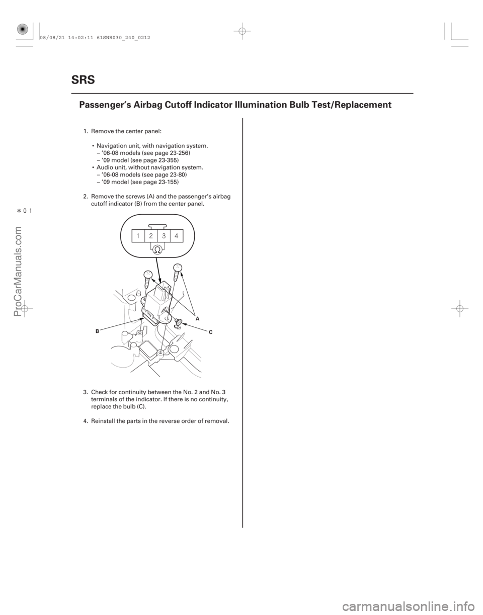
24-212SRS
Passenger’s Airbag Cutoff Indicator Illumination Bulb Test/Replacement
B
A
C
1. Remove the center panel: Navigation unit, with navigation system.– ’06-08 models (see page 23-256)
– ’09 model (see page 23-355)
Audio unit, without navigation system. – ’06-08 models (see page 23-80)
– ’09 model (see page 23-155)
2. Remove the screws (A) and the passenger’s airbag cutoff indicator (B) from the center panel.
3. Check for continuity between the No. 2 and No. 3 terminals of the indicator. If there is no continuity,
replace the bulb (C).
4. Reinstall the parts in the reverse order of removal.
08/08/21 14:02:11 61SNR030_240_0212
ProCarManuals.com
DYNOMITE -2009-