Page 2110 of 2893

COMBINATION LIGHT SWITCH 12P CONNECTOR
COMBI GND (BLK)
H/L ON
SW (PNK) UNDER-DASH FUSE/RELAY B")
�Î�����µ
�µ
�µ
�µ �µ
�µ
YES
NO
YES
NO YES
NO
22-162
Exterior Lights
DTC Troubleshooting (cont’d)
COMBINATION LIGHT SWITCH 12P CONNECTOR
COMBI GND (BLK)
H/L ON
SW (PNK) UNDER-DASH FUSE/RELAY BOX CONNECTOR S (20P)
COMBI GND
(BLK)
H/L ON SW (PNK) PASSING
SW (RED)
PASSING
SW (RED)
DIMMER SW (LT BLU) DIMMER SW
(LT BLU)
17. Turn the ignition switch to LOCK (0).
18. Do the combination light switch test (see page
22-166).
Go to step 19.
Replace the combination light switch.
19. Disconnect under-dash fuse/relay box connector S (20P).
20. Check for continuity between under-dash fuse/relay box connector S (20P) terminals and the
combination light switch 12P connector terminals
as shown:
Under-dash fuse/
relay box connector S (20P) Combination light
switch 12P connector
512
11 10
12 6
16 4
Go to step 21.
Repair an open in the wire. 21. Check for continuity between under-dash fuse/relay
box connector S (20P) terminals as shown:
From terminal To terminal 12 1, 11, 13, 16
16 1, 11, 13
Repair a short between the wires.
Faulty MICU; replace the under-dash fuse/
relay box (see page 22-66).
Wire side of female terminals
Wire side of female terminals
I s t he combi nat i on l i ght sw i t ch OK ?
Is there continuity? Is there continuity?
08/08/21 14:26:58 61SNR030_220_0164
ProCarManuals.com
DYNOMITE -2009-
Page 2111 of 2893
����
22-163
MICU Input Test
UNDER-DASH FUSE/RELAY BOX CONNECTOR E (42P)
BLK RED
GRN WHT
ORN
PNKPUR
WHT
GRY LT BLU UNDER-DASH FUSE/RELAY BOX CONNECT")
����
�(�#�'���������������
���������
�����
�������)����
22-163
MICU Input Test
UNDER-DASH FUSE/RELAY BOX CONNECTOR E (42P)
BLK RED
GRN WHT
ORN
PNKPUR
WHT
GRY LT BLU UNDER-DASH FUSE/RELAY BOX CONNECTOR F (34P)
UNDER-DASH FUSE/RELAY BOX CONNECTOR G (21P)
UNDER-DASH FUSE/RELAY BOX CONNECTOR S (20P) UNDER-DASH FUSE/RELAY BOX CONNECTOR T (34P) BLK
BLK BLK
RED
RED
RED ORN
PNK BLK
NOTE:
The MICU turns on the headlights (high beams) in a dimming mode for the Daytime Running Lights under the following conditions:
– With the ignition switch turned to ON (II)
– The headlight switch OFF
– The parking brake is released (parking brake switch OFF)
The DRL indicator will come on when one of the headlight (high beams) bulbs is blown, or if the high beam wiring has an open circuit with the daytime running lights ON.
If the vehicle is equipped with an optional remote control engine start system, the daytime running lights will not function when started with the remote start.
1. Before testing the lighting system, troubleshoot the system using B-CAN System Diagnosis Test Mode A (see page 22-93).
2. Check the No. 12 (10 A), No. 13 (10 A), No. 15 (7.5 A), No. 16 (15 A) , (10 A) , No. 17 (15 A) , (10 A) , No. 18 (20 A), No. 19 (15 A), No. 21 (30 A) , (20 A) , and No. 37 (7.5 A) fuses in the under-dash fuse/relay box. If any fuse
is blown, replace it and go to step 3.
1: With HID
2: Without HID
3. Disconnect under-dash fuse/relay box connectors E, F, G, S, and T. NOTE: All connector views are shown from wire side of female terminals.
(cont’d)
1212
12
08/08/21 14:26:58 61SNR030_220_0165
ProCarManuals.com
DYNOMITE -2009-
Page 2113 of 2893

Cavity WireTest condition Test: Desired result Possible cause if desired result is not
obtained
22-165
6. Reconnect the connectors to the under-dash fuse/relay box, and do these input tests at the following connectors.
If any test indicates a problem, find and correct the cause, then recheck the system.
If all the input tests prove OK, the MICU must be faulty; replace the under-dash fuse/relay box.
G2 ORN Under all conditions Measure the voltage between
terminal G2 and body ground:
There should be battery voltage.Blown No. 23 (10 A) fuse in the under-
hood fuse/relay box
An open in the wire
G18 WHT Under all conditions Measure the voltage between terminal G18 and body ground:
There should be battery voltage.Blown No. 4 (50 A) fuse in the under-
hood fuse/relay box
An open in the wire
E6 BLK Under all conditions Measure the voltage to ground: There should be less than 0.5 V.Poor ground (G602)
An open in the wire
E33 BLK Under all conditions Measure the voltage to ground: There should be less than 0.5 V.Poor ground (G601)
An open in the wire
F20 BLK Under all conditions Measure the voltage to ground: There should be less than 0.5 V.Poor ground (G401)
An open in the wire
T34 BLK Under all conditions Measure the voltage to ground: There should be less than 0.5 V.Poor ground (G501)
An open in the wire
S1 ·
S5 ORN
·
BLK Combination light switch OFF Measure the voltage between
terminals S1 and S5:
There should be less than 1 V. Faulty combination light switch
An open in the wire
Combination light switch in any
other position than OFF Measure the voltage between
terminals S1 and S5:
There should be more than 5 V. Faulty combination light switch
A short to ground in the wire
S11 ·
S5 PNK
·
BLK Combination light switch
(Headlight position) ON
Measure the voltage between
terminals S11 and S5:
There should be less than 1 V. Faulty combination light switch
An open in the wire
Combination light switch OFF Measure the voltage between terminals S11 and S5:
There should be more than 5 V. Faulty combination light switch
A short to ground in the wire
S12 ·
S5 RED
·
BLK Combination light switch lever
pulled (Passing)
Measure the voltage between
terminals S12 and S5:
There should be less than 1 V. Faulty combination light switch
An open in the wire
Combination light switch lever
released from passing position Measure the voltage between
terminals S12 and S5:
There should be more than 5 V. Faulty combination light switch
A short to ground in the wire
S13 ·
S5 GRY
·
BLK Combination light switch
(SMALL position) ON
Measure the voltage between
terminals S13 and S5:
There should be less than 1 V. Faulty combination light switch
An open in the wire
Combination light switch OFF Measure the voltage between terminals S13 and S5:
There should be more than 5 V. Faulty combination light switch
A short to ground in the wire
S16 ·
S5 LT BLU
·
BLK Combination light switch
(Dimmer) in high beam position
Measure the voltage between
terminals S16 and S5:
There should be less than 1 V. Faulty combination light switch
An open in the wire
Combination light switch
(Dimmer) in low beam position Measure the voltage between
terminals S16 and S5:
There should be more than 5 V. Faulty combination light switch
A short to ground in the wire
C3 ORN Ignition switch ON (II) Measure the voltage between terminal C3 and body ground:
There should be battery voltage.Faulty ignition switch
An open in the wire
08/08/21 14:26:58 61SNR030_220_0167
ProCarManuals.com
DYNOMITE -2009-
Page 2118 of 2893
����
�µ
�µ �µ
�µ
Special Tools Required
YES
NO YES
NO
22-170Exterior Lights
HID Lamp System Troubleshooting
A
B
A transient high tension (25,000")
���
�(�#�'�����!���������
�����
�����������������)����
�µ
�µ �µ
�µ
Special Tools Required
YES
NO YES
NO
22-170Exterior Lights
HID Lamp System Troubleshooting
A
B
A transient high tension (25,000 V) occurs at the
bulb sockets or the high intensity discharge (HID)
lamps when the combination light switch is turned
ON, it may cause serious electrical shock or
electrocution if you do not observe the cautions.
Never turn on the combination light switch before fitting the HID bulbs to their bulb sockets
and completing the reassembly of the headlight
assembly.
Do not service the headlights assembly in wet conditions, such as rain or snow, near a sprinkler
system, or when your hands are wet to prevent
electrocution.
Do not touch the surface of the HID bulbs with your bare hands and do not stain it with any oils
and fats.
Do not disassemble the inverter unit and the igniter unit.
Do not turn on the HID bulb by using a power source other than the battery mounted on your
vehicle.
HID bulb test light 07AAJ-S3MA100
NOTE: Before troubleshooting the HID Lamp System,
do the multiplex integrated control system
troubleshooting using B-CAN System Diagnosis Test
Mode A (see page 22-93). 1. Check the No. 16 (15 A), No. 17 (15 A), and No. 21 (30 A) fuses in the under-dash fuse/relay box.
Go to step 2.
Replace the fuse(s), and recheck.
2. Turn the combination light switch OFF.
3. Do the battery terminal disconnection procedure (see page 22-68). 4. Remove the socket from the HID bulb (see page
22-168).
5. Check for corrosion (A) and traces of electrical arcing (B) at the socket mating part.
Go to step 7.
Replace the socket, and recheck.
Ar e f uses OK ? I s t he sock et cor r od ed or bur nt ?
08/08/21 14:27:00 61SNR030_220_0172
ProCarManuals.com
DYNOMITE -2009-
Page 2120 of 2893

HID UNIT 2P CONNECTOR
LEFT HEADLIGHT (PUR)
RIGHT HEADLIGHT (")
��������
����
�µ
�µ
�µ
�µ
YES
NO
LEFT HEADLIGHT
RIGHT HEADLIGHT
YES
NO
22-172Exterior Lights
HID Lamp System Troubleshooting (cont’d)
HID UNIT 2P CONNECTOR
LEFT HEADLIGHT (PUR)
RIGHT HEADLIGHT (GRN)
HID UNIT 2P CONNECTOR (LEFT HEADLIGHT)PUR
UNDER-DASH FUSE/RELAY BOX CONNECTOR G (21P)
UNDER-DASH FUSE/RELAY BOX CONNECTOR F (34P) HID UNIT 2P CONNECTOR (RIGHT HEADLIGHT) GRN
16. Measure the voltage between the HID unit 2P
connector terminal No. 2 and body ground.
Substitute a known-good HID unit, and
recheck. If the symptom/indication goes away,
replace the original HID unit.
Go to step 17.
17. Disconnect under-dash fuse/relay box connector G (21P) and/or F (34P) .1: Left headlight
2: Right headlight 18. Check for continuity between under-dash fuse/relay
box G (21P) terminal No. 17 or F (34P) terminal
No. 4 and HID unit 2P connector terminal No. 2.
Replace the under-dash fuse/relay box.
Repair an open in the wire between the
under-hood fuse/relay box and the HID unit.
12
Wire side of female terminals
Wire side of female terminalsWire side of female terminals
Wire side of female terminals Wire side of female terminals
Is there battery voltage?
Is there continuity?
08/08/21 14:27:00 61SNR030_220_0174
ProCarManuals.com
DYNOMITE -2009-
Page 2132 of 2893
����
�(�#�'���������������
�����������������������)����
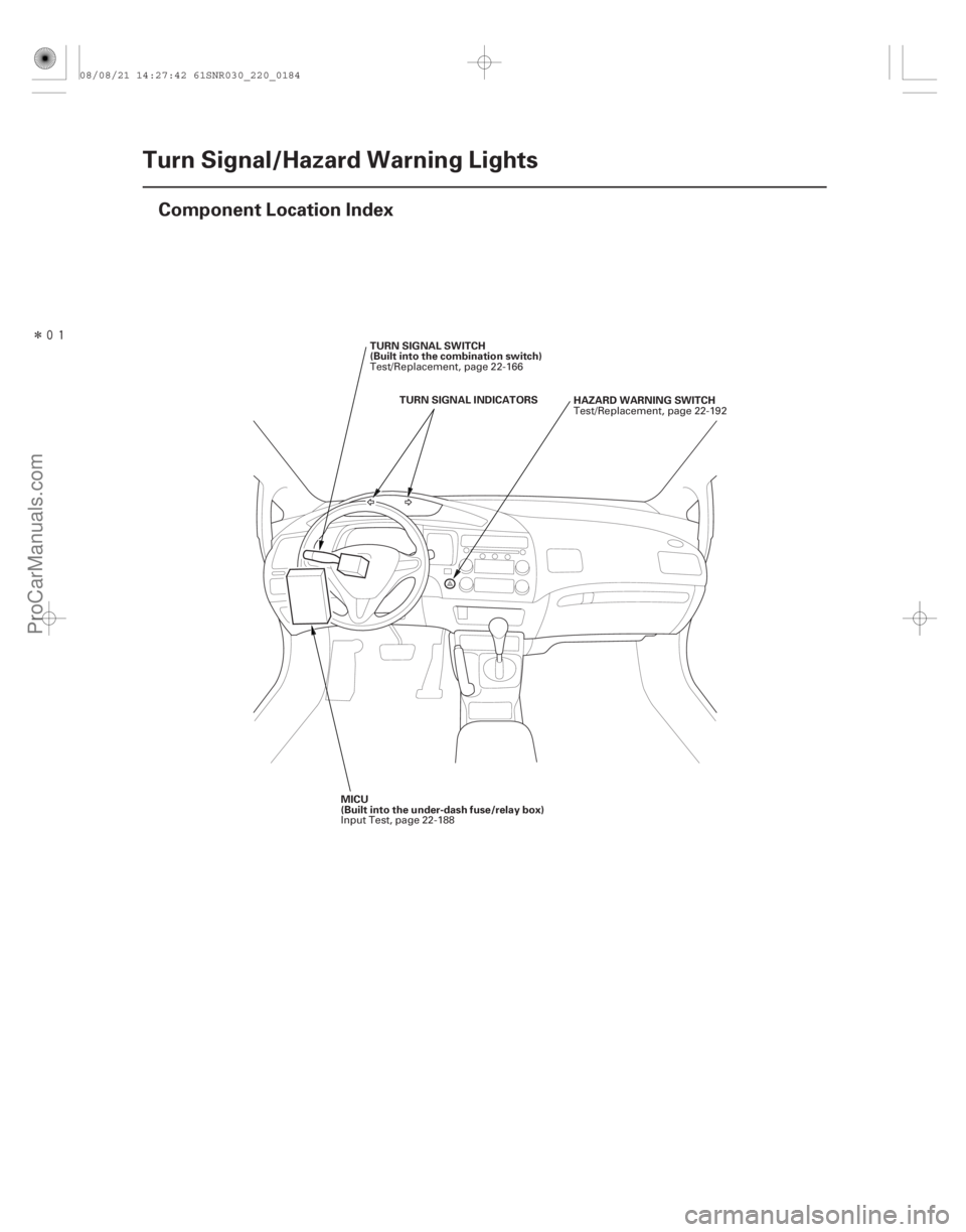
22-182Turn Signal/Hazard Warning Lights
Component Location Index
HAZARD WARNING SWITCH
TURN SIGNAL INDICATORS
TURN SIGNAL SWITCH
(Built into the combination switch)
MICU
(Built into the under-dash fuse/relay box) Test/Replacement, page 22-192
Test/Replacement, page 22-166
Input Test, page 22-188
08/08/21 14:27:42 61SNR030_220_0184
ProCarManuals.com
DYNOMITE -2009-
Page 2134 of 2893
������(�#�'���������������
�����������������������)����
�´
22-184Turn Signal/Hazard Warning Lights
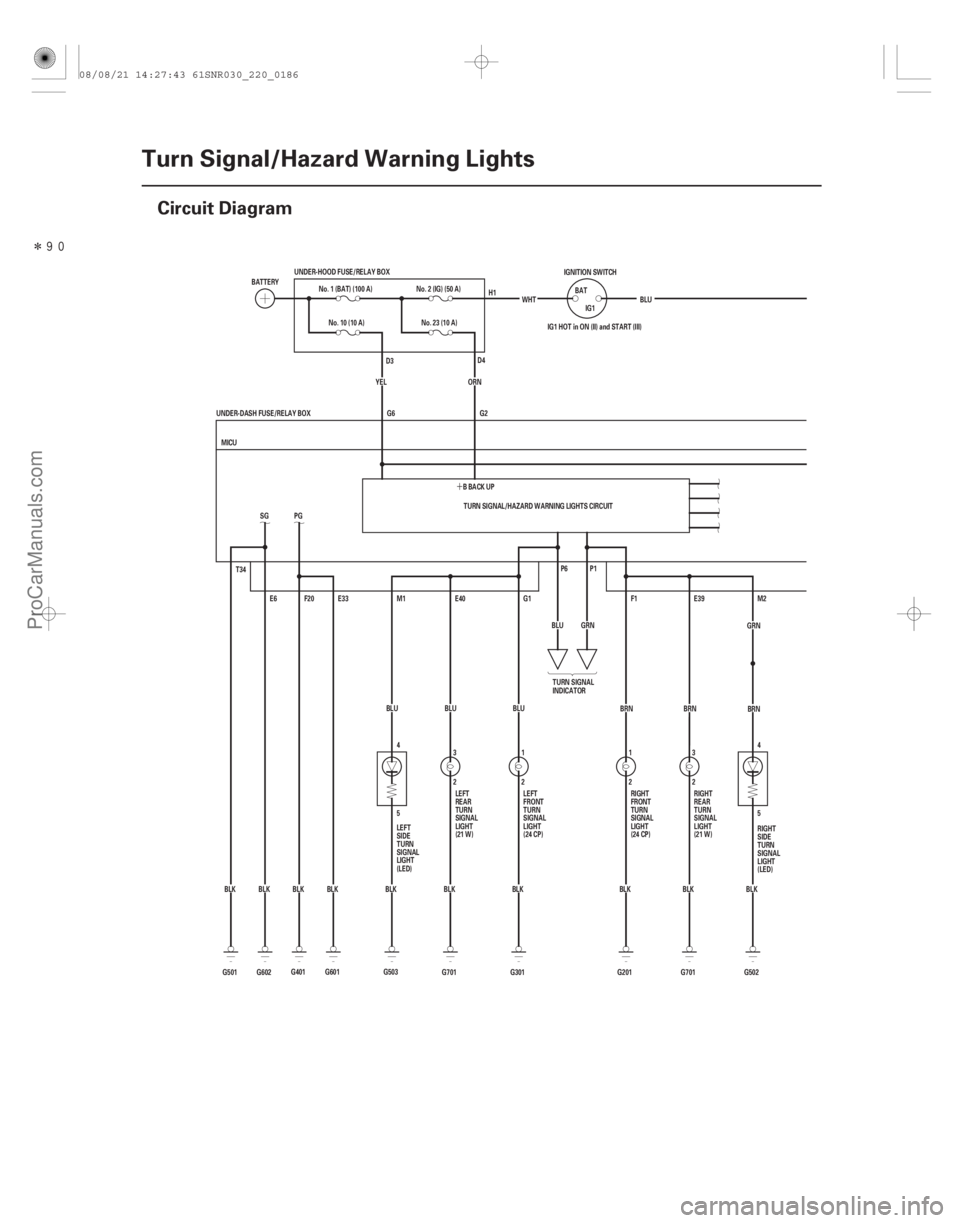
Circuit Diagram
4
5
5 4
G701BLU
3
2E40
BLK E39
2 3
BRN
G701 BLK
T34
G602BLKSG
E6
G501 BLK TURN SIGNAL/HAZARD WARNING LIGHTS CIRCUIT
G2
G6
BLK
BLK
BLK
BLK
BLK WHT
IG1 HOT in ON (II) and START (III)
P1
P6
M2
G502
F1
G201 2
1
BRN
GRN
BLU
G1
G301 BLU
1
2
MICU
UNDER-DASH FUSE/RELAY BOX IG1
BAT
IGNITION SWITCH
BLU
No. 10 (10 A)
E33
F20
PG
G601 BBACKUP
ORN
M1
YEL
BLK
G401 BLUNo. 23 (10 A)
BATTERY
No. 1 (BAT) (100 A)
UNDER-HOOD FUSE/RELAY BOX
No. 2 (IG) (50 A)
G503 TURN SIGNAL
INDICATOR
LEFT
SIDE
TURN
SIGNAL
LIGHT
(LED) RIGHT
SIDE
TURN
SIGNAL
LIGHT
(LED)
RIGHT
FRONT
TURN
SIGNAL
LIGHT
(24 CP)
LEFT
FRONT
TURN
SIGNAL
LIGHT
(24 CP) RIGHT
REAR
TURN
SIGNAL
LIGHT
(21 W)
LEFT
REAR
TURN
SIGNAL
LIGHT
(21 W) H1
D4
D3
BRN
GRN
08/08/21 14:27:43 61SNR030_220_0186
ProCarManuals.com
DYNOMITE -2009-
Page 2135 of 2893
�����
22-185
D2
COMBINATION LIGHT SWITCH 5
2 4
1
12 2 1
BLK S5
BRNS18
S19
LT GRN
LEFT RIGHT MICU
UNDER-DASH FUSE/RELAY BOX BLU
Q11 REDGRY
WHT
GRN
R1
DASH LIGHTS
BRIGHTNESS
CONTROLLER
TURN
SIGNAL
SWITCH HAZARD
WARNING
SWITCH
No. 10
(7.5 A)
LIGHT
(0.56 W)
No.14(7.5A)FUSE
(UNDER-DASH
FUSE/RELAY BOX)
08/08/21 14:27:43 61SNR030_220_0187
ProCarManuals.com
DYNOMITE -2009-