Page 2046 of 2893
����
22-99
Sleep and Wake-up Mode Test
1. Shift to the sleep mode:Turn the ignition switch to LOCK (0), and remove the key. If the MICU receives no signal")
�(�#�'���������������������������������������)����
22-99
Sleep and Wake-up Mode Test
1. Shift to the sleep mode:Turn the ignition switch to LOCK (0), and remove the key. If the MICU receives no signals from the inputs listed
below, it will go into sleep mode in less than 40 seconds.
Driver’s door lock switch (LOCK or UNLOCK)
Driver’s door key cylinder switch (LOCK or UNLOCK)
Front passenger’s door lock switch (LOCK or UNLOCK)
Trunk lid latch switch (Trunk lid closed)
Hazard warning switch (OFF)
2. Confirm the sleep mode: Measure the frequency on the B-CAN communication line (PNK wire); there should be 0 Hz when the system is in
the sleep mode. Check the parasitic draw at the battery while shifting into the sleep mode; the amperage should
change from about 200 mA to less than 35 mA.
3. Shift to the wake up mode: When the ignition switch is turned to ON (II), the MICU, gauge control module, immob ilizer-keyless control unit,
and ECM/PCM wake up at the same time without ‘‘talking’’ to each other through the communication lines. When
any switch in the multiplex integrated control system is turned on, it wakes up its related control unit which, in
turn, wakes up the other units. After confirming the sleep mode, look in the following table for the switch most
related to the problem. Operate that switch and see if its control unit wakes up.
NOTE: If any control unit is faulty and will not wake up, several circuits in the system will malfunction at the same
time. In the table below, the control unit is followed by a list of the switches and input signals that can wake it up.
Door switches (door open)
Driver’s door lock switch (LOCK or UNLOCK)
Driver’s door lock knob switch (LOCK or UNLOCK)
Driver’s door key cylinder switch (LOCK or UNLOCK)
Front passenger’s door lock switch (LOCK or UNLOCK)
Front passenger’s door lock knob switch (LOCK or UNLOCK)
Left rear door lock knob switch
Right rear door lock knob switch
Trunk lid latch switch (Trunk lid open)
Hood switch (with security) (hood open)
Hazard warning switch (ON)
Combination light switch (Parking, Headlight, Dimmer, Passing ON)
Ignition key switch (key inserted)
08/08/21 14:25:00 61SNR030_220_0101
ProCarManuals.com
DYNOMITE -2009-
Page 2132 of 2893
����
�(�#�'���������������
�����������������������)����
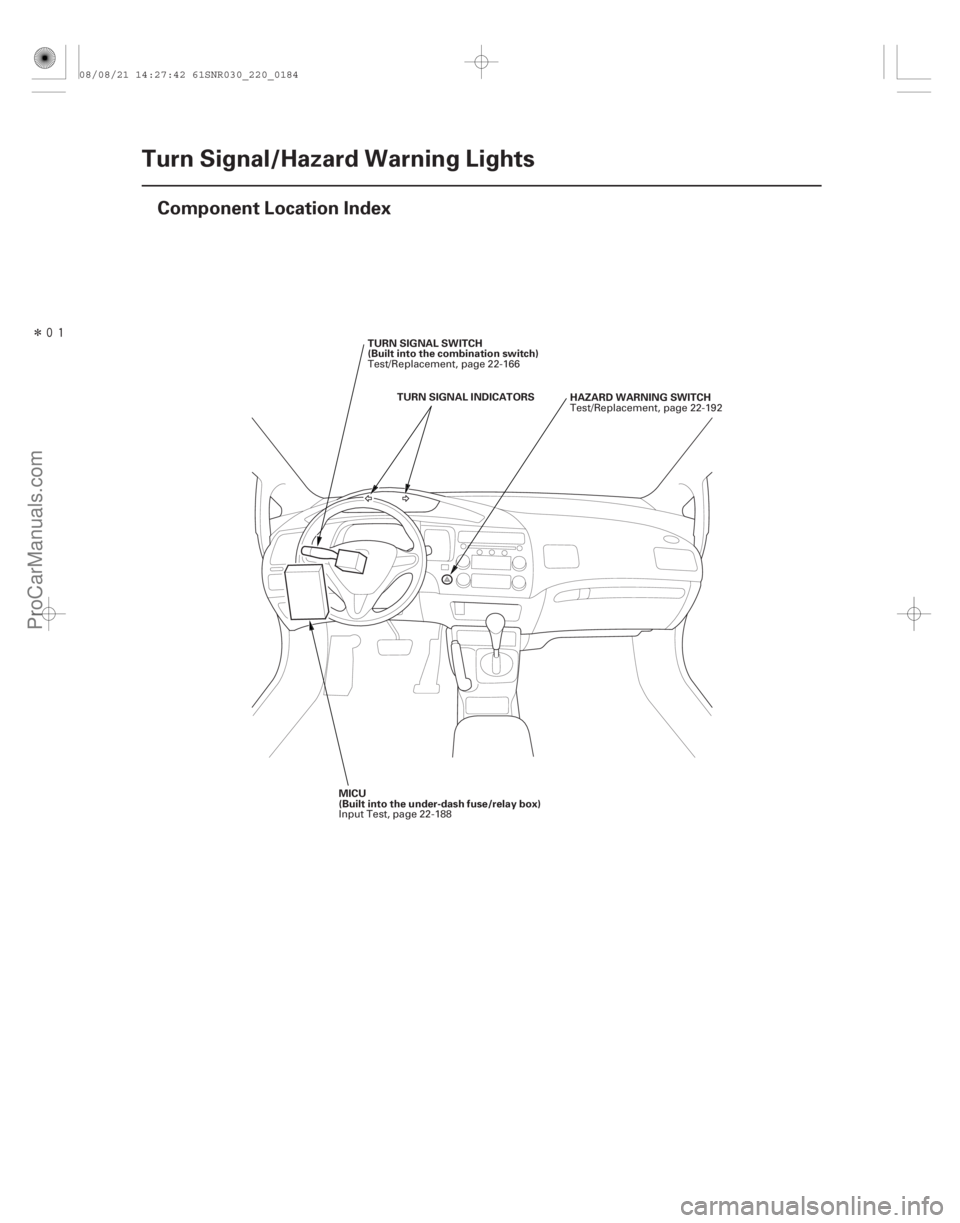
22-182Turn Signal/Hazard Warning Lights
Component Location Index
HAZARD WARNING SWITCH
TURN SIGNAL INDICATORS
TURN SIGNAL SWITCH
(Built into the combination switch)
MICU
(Built into the under-dash fuse/relay box) Test/Replacement, page 22-192
Test/Replacement, page 22-166
Input Test, page 22-188
08/08/21 14:27:42 61SNR030_220_0184
ProCarManuals.com
DYNOMITE -2009-
Page 2134 of 2893
������(�#�'���������������
�����������������������)����
�´
22-184Turn Signal/Hazard Warning Lights
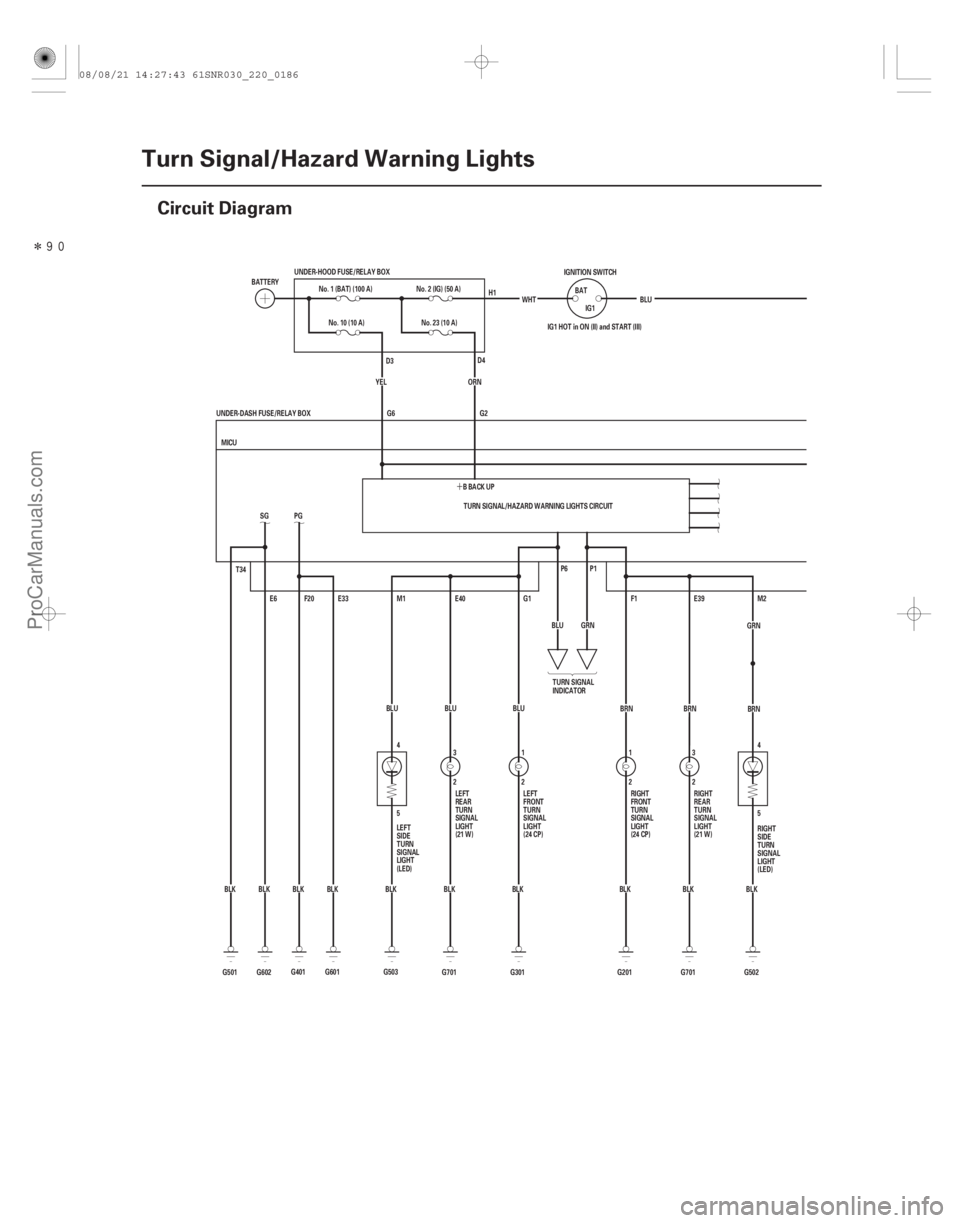
Circuit Diagram
4
5
5 4
G701BLU
3
2E40
BLK E39
2 3
BRN
G701 BLK
T34
G602BLKSG
E6
G501 BLK TURN SIGNAL/HAZARD WARNING LIGHTS CIRCUIT
G2
G6
BLK
BLK
BLK
BLK
BLK WHT
IG1 HOT in ON (II) and START (III)
P1
P6
M2
G502
F1
G201 2
1
BRN
GRN
BLU
G1
G301 BLU
1
2
MICU
UNDER-DASH FUSE/RELAY BOX IG1
BAT
IGNITION SWITCH
BLU
No. 10 (10 A)
E33
F20
PG
G601 BBACKUP
ORN
M1
YEL
BLK
G401 BLUNo. 23 (10 A)
BATTERY
No. 1 (BAT) (100 A)
UNDER-HOOD FUSE/RELAY BOX
No. 2 (IG) (50 A)
G503 TURN SIGNAL
INDICATOR
LEFT
SIDE
TURN
SIGNAL
LIGHT
(LED) RIGHT
SIDE
TURN
SIGNAL
LIGHT
(LED)
RIGHT
FRONT
TURN
SIGNAL
LIGHT
(24 CP)
LEFT
FRONT
TURN
SIGNAL
LIGHT
(24 CP) RIGHT
REAR
TURN
SIGNAL
LIGHT
(21 W)
LEFT
REAR
TURN
SIGNAL
LIGHT
(21 W) H1
D4
D3
BRN
GRN
08/08/21 14:27:43 61SNR030_220_0186
ProCarManuals.com
DYNOMITE -2009-
Page 2135 of 2893
�����
22-185
D2
COMBINATION LIGHT SWITCH 5
2 4
1
12 2 1
BLK S5
BRNS18
S19
LT GRN
LEFT RIGHT MICU
UNDER-DASH FUSE/RELAY BOX BLU
Q11 REDGRY
WHT
GRN
R1
DASH LIGHTS
BRIGHTNESS
CONTROLLER
TURN
SIGNAL
SWITCH HAZARD
WARNING
SWITCH
No. 10
(7.5 A)
LIGHT
(0.56 W)
No.14(7.5A)FUSE
(UNDER-DASH
FUSE/RELAY BOX)
08/08/21 14:27:43 61SNR030_220_0187
ProCarManuals.com
DYNOMITE -2009-
Page 2138 of 2893
���
�(�#�'���������������
���������
�����
�������)����
22-188Turn Signal/Hazard Warning Lights
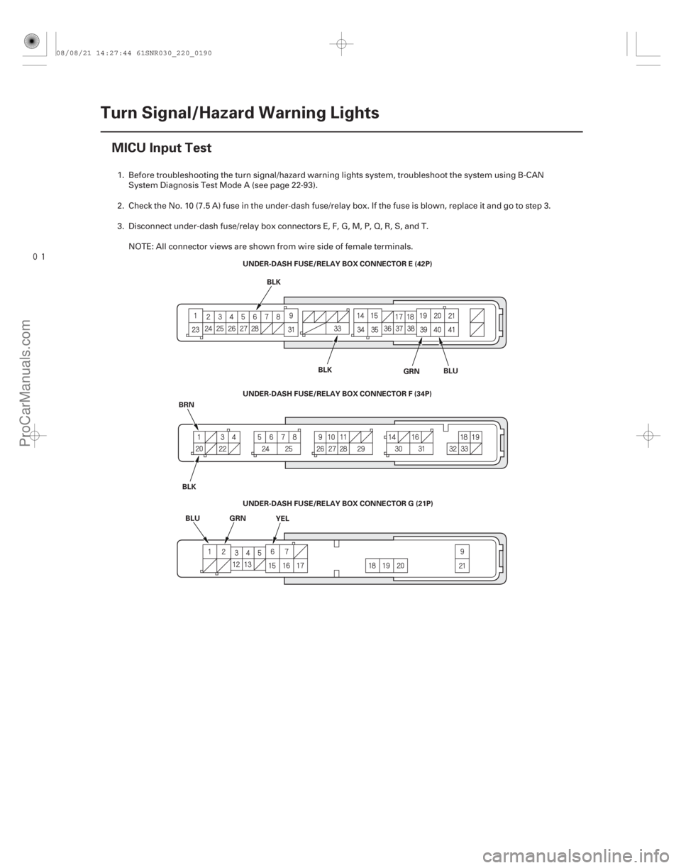
MICU Input Test
UNDER-DASH FUSE/RELAY BOX CONNECTOR E (42P)
BLK
BRN BLU UNDER-DASH FUSE/RELAY BOX CONNECTOR F (34P)
UNDER-DASH FUSE/RELAY BOX CONNECTOR G (21P)
YEL BLK
BLK BLU
GRN GRN
1. Before troubleshooting the turn signal/hazard warning lights system, troubleshoot the system using B-CAN
System Diagnosis Test Mode A (see page 22-93).
2. Check the No. 10 (7.5 A) fuse in the under-dash fuse/relay box. If the fuse is blown, replace it and go to step 3.
3. Disconnect under-dash fuse/relay box connectors E, F, G, M, P, Q, R, S, and T. NOTE: All connector views are shown from wire side of female terminals.
08/08/21 14:27:44 61SNR030_220_0190
ProCarManuals.com
DYNOMITE -2009-
Page 2140 of 2893

5. With the connectors still disconne")
Cavity Wire Test conditionTest: Desired result Possible cause if result desired is
not obtained
22-190Turn Signal/Hazard Warning Lights
MICU Input Test (cont’d)
5. With the connectors still disconnected, do these input tests at the following connectors.
If any test indicates a problem, find and correct the cause, then recheck the system.
If all the input tests prove OK, go to step 6.
E39 BRN Under all conditions Connect terminals G2 and E39
with a jumper wire:
The right rear turn signal light
should come on.Poor ground (G701)
Blown bulb
An open in the wire
E40 BLU Under all conditions Connect terminals G2 and E40 with a jumper wire:
The left rear turn signal light
should come on.Poor ground (G701)
Blown bulb
An open in the wire
F1 BRN Under all conditions Connect terminals G2 and F1 with a jumper wire:
The right front turn signal light
should come on.Poor ground (G201)
Blown bulb
An open in the wire
G1 BLU Under all conditions Connect terminals G2 and G1 with a jumper wire:
The left front turn signal light
should come on.Poor ground (G301)
Blown bulb
An open in the wire
M1 BLU Under all conditions Connect terminals G2 and M1 with a jumper wire:
The left side turn signal light
should come on.Poor ground (G503)
Blown LED
An open in the wire
M2 GRN Under all conditions Connect terminals G2 and M2 with a jumper wire:
The right side turn signal light
should come on.Poor ground (G502)
Blown LED
An open in the wire
P1 GRN Under all conditions Connect terminals G2 and P1 with a jumper wire:
The right turn signal indicator
should come on.Poor ground (G504)
Faulty gauge control module
(speedo)
An open in the wire
P6 BLU Under all conditions Connect terminals G2 and P6 with a jumper wire:
The left turn signal indicator
should come on.Poor ground (G504)
Faulty gauge control module
(speedo)
An open in the wire
08/08/21 14:27:44 61SNR030_220_0192
ProCarManuals.com
DYNOMITE -2009-
Page 2141 of 2893

Cavity Wire Test conditionTest: Desired result Possible cause if desired result is
not obtained
22-191
6. Reconnect connectors to the under-dash fuse/relay box, and do these input tests at the following connectors.
If any test indicates a problem, find and correct the cause, then recheck the system.
If all the input tests prove OK, the MICU must be faulty; replace the under-dash fuse/relay box.
G2 ORN Under all conditions Measure the voltage between
terminal G2 and body ground:
There should be battery voltage.Blown No. 23 (10 A) fuse in the
under-hood fuse/relay box
An open in the wire
G6 YEL Under all conditions Measure the voltage between terminal G6 and body ground:
There should be battery voltage.Blown No. 10 (10 A) fuse in the
under-hood fuse/relay box
An open in the wire
E6 BLK Under all conditions Measure the voltage to ground: There should be less than 0.5 V.Poor ground (G602)
An open in the wire
E33 BLK Under all conditions Measure the voltage to ground: There should be less than 0.5 V.Poor ground (G601)
An open in the wire
F20 BLK Under all conditions Measure the voltage to ground: There should be less than 0.5 V.Poor ground (G401)
An open in the wire
T34 BLK Under all conditions Measure the voltage to ground: There should be less than 0.5 V.Poor ground (G501)
An open in the wire
R1 WHT Under all conditions Measure the voltage to ground: There should be battery voltage.Faulty under-dash fuse/relay box
Q11 GRN Hazard warning switch ON Measure the voltage to ground:
There should be battery voltage. Blown No. 23 (10 A) fuse in the
under-hood fuse/relay box
Faulty hazard warning switch
An open in the wire
S18 ·
S5 BRN
·
BLK Turn signal switch in
right position
Measure the voltage between
terminals S18 and S5:
There should be less than 0.5 V. Faulty combination light switch
An open in the wire
Turn signal switch in
left or neutral
position Measure the voltage between
terminals S18 and S5:
There should be 5 V or more. Faulty combination light switch
A short to ground in the wire
S19 ·
S5 LT
GRN ·
BLK Turn signal switch in
left position
Measure the voltage between
terminals S19 and S5:
There should be less than 0.5 V. Faulty combination light switch
An open in the wire
Turn signal switch in
right or neutral
position Measure the voltage between
terminals S19 and S5:
There should be 5 V or more. Faulty combination light switch
A short to ground in the wire
08/08/21 14:27:44 61SNR030_220_0193
ProCarManuals.com
DYNOMITE -2009-
Page 2142 of 2893
���� ���
����
�(�#����������������
����������������� �����)���
22-19222-192 Turn Signal/Hazard Warning Lights
Hazard Warning Switch Test/")
���
����
�����(�#�'���������������
���������
�����
�������)���� ���
����
�(�#�'���������������
����������������� �����)���
22-19222-192 Turn Signal/Hazard Warning Lights
Hazard Warning Switch Test/
Replacement
Side Turn Signal Light Replacement
A
A
Terminal
Position 12
4
5
OFF ON A
A
B
1. Remove the center panel. With audio:– ’06-08 models (see page 23-80)
– ’09 model (see page 23-256)
With navigation: – ’06-08 models (see page 23-155)
– ’09 model (see page 23-355)
2. Remove the screws and the hazard warning switch (A).
3. Check for continuity between the terminals in each switch position according to the table.
4. If the continuity is not as specified, replace the bulb (A) or the hazard warning switch.
5. Install the hazard warning switch in the reverse order of removal. 1. Remove the mirror holder (see page 20-34).
2. Remove the four screws and the mirror visor (A).
3. Disconnect the 2P connector (A) from the side turn
signal light (B), then remove the side turn signal
light.
4. Install the side turn signal light in the reverse order of removal.
08/08/21 14:27:45 61SNR030_220_0194
ProCarManuals.com
DYNOMITE -2009-