Page 2205 of 2893
�����
�µ
22-255
B
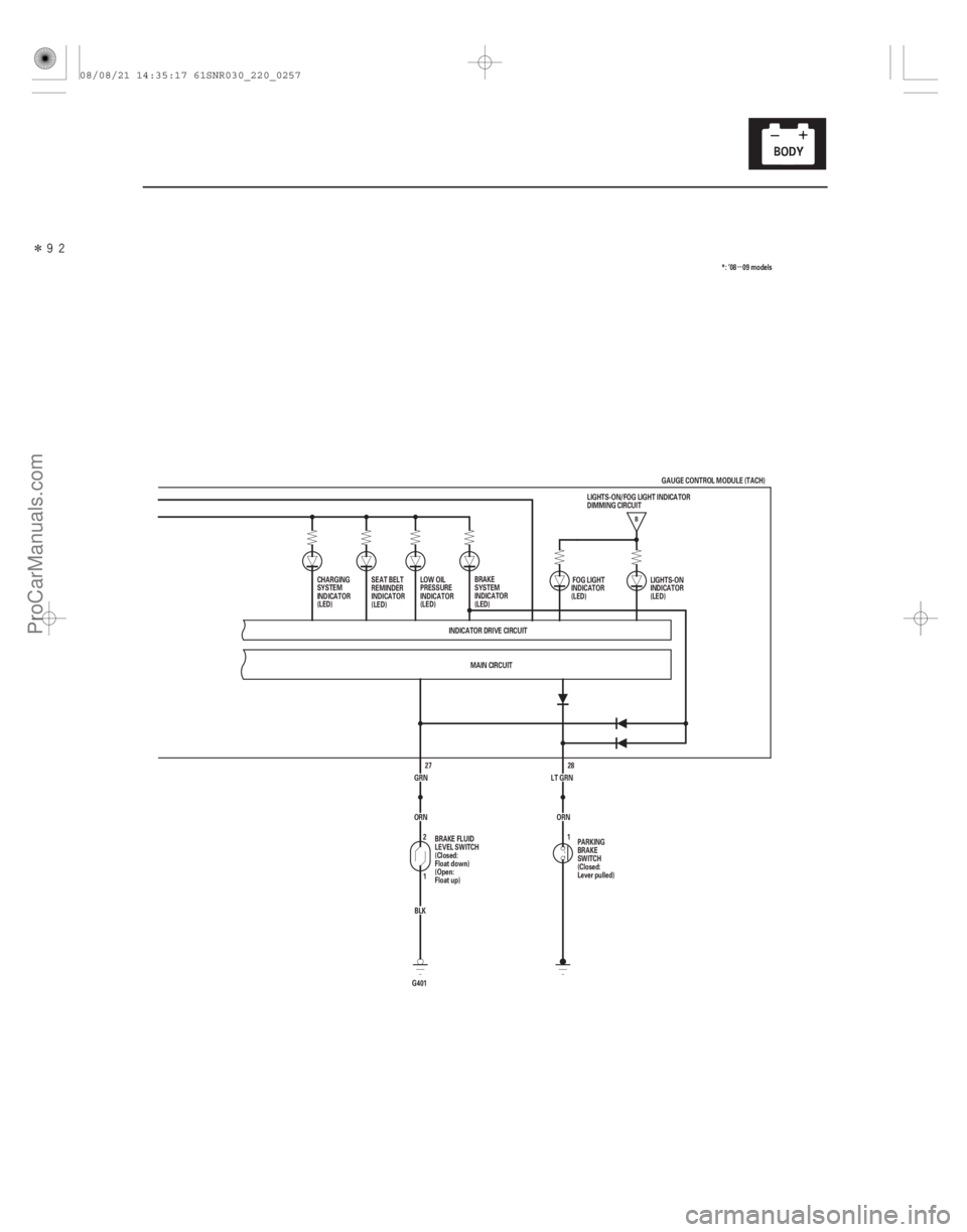
28
LT GRN
MAIN CIRCUIT
INDICATOR DRIVE CIRCUIT
SEAT BELT
REMINDER
INDICATOR
(LED)
LOW OIL
PRESSURE
INDICATOR
(LED)
PARKING
BRAKE
SWITCH
(Closed:
Lever pulled)LIGHTS-ON
INDICATOR
(LED)
1 FOG LIGHT
INDICATOR
(LED)
BRAKE
SYSTEM
INDICATOR
(LED) *: ’08 09 models
GRN BLK
G401 1 2
ORN 27
BRAKE FLUID
LEVEL SWITCH
(Closed:
Float down)
(Open:
Float up) ORN
CHARGING
SYSTEM
INDICATOR
(LED)
GAUGE CONTROL MODULE (TACH)
LIGHTS-ON/FOG LIGHT INDICATOR
DIMMING CIRCUIT
08/08/21 14:35:17 61SNR030_220_0257
ProCarManuals.com
DYNOMITE -2009-
Page 2206 of 2893
����
�µ
�´
�µ
22-256 Gauges
Circuit Diagram - Dash Lights Brightness Controller
RED
GRY
BRN45
YEL 6
BLU 7
PUR
BLK
2176
4
G501 13
RED
14
16
BLK B")
����
�(�#�'���������������������
�����������������)����
�µ
�´
�µ
22-256 Gauges
Circuit Diagram - Dash Lights Brightness Controller
RED
GRY
BRN45
YEL 6
BLU 7
PUR
BLK
2176
4
G501 13
RED
14
16
BLK BLK
G503
13
RED
16
BLK BLK
G504 15
MAIN CIRCUIT
WHT BRN
No. 2 (IG) (50 A)
GAUGE CONTROL MODULE (TACH) 18 17
ORN
IG1
BAT
BLU
WHT
No. 23 (10 A)
BATTERY
IGNITION SWITCH
No. 1 (BAT) (100 A)
(7.5 A) No. 10
UNDER-DASH
FUSE/RELAY
BOX IG1 HOT in ON (II)
and START (III)
DASH LIGHTS BRIGHTNESS CONTROLLER and
ODOMETER SELECT/RESET SWITCH
No. 14 (7.5 A) FUSE
(UNDER-DASH
FUSE/RELAY BOX)
GAUGE CONTROL
MODULE (TACH) km/h
mph
SEL/
RESET
ILLUMI
()
ILLUMI
()
H1
D4 G2D2
UNDER-HOOD FUSE/RELAY BOX
5
3LIGHTS
(LED) Q1 Q9
MICU A/T GEAR POSITION INDICATOR
PANEL LIGHT
AMBIENT LIGHT
SEAT HEATER SWITCHES LIGHT
DRIVER’S FOOTWELL LIGHT*1
FRONT PASSENGER’S
FOOTWELL LIGHT*1
CLIMATE CONTROL UNIT*2
DASH LIGHTS BRIGHTNESS
CONTROLLER*2
FRONT PASSENGER’S
AIRBAG CUTOFF INDICATOR*2
VSA OFF SWITCH*2
AUDIO UNIT
NAVIGATION UNIT
HAZARD WARNING SWITCH LIGHT
MOONROOF SWITCH LIGHT
STEERING SWITCHES LIGHT
CLIMATE CONTROL UNIT*1
DASH LIGHTS BRIGHTNESS
CONTROLLER*1
FRONT PASSENGER’S
AIRBAG CUTOFF INDICATOR*1
VSA OFF SWITCH*1
*1: TYPE S model
*2: Except TYPE S model
08/08/21 14:35:17 61SNR030_220_0258
ProCarManuals.com
DYNOMITE -2009-
Page 2209 of 2893
�����
22-259
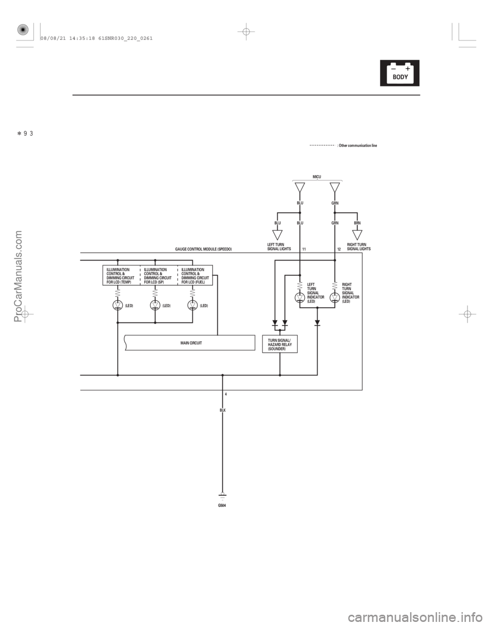
MICU
BLU GRN
BLU GRN
(LED)
(LED)
(LED)
G504G504 12
BRN
BLU
MAIN CIRCUIT BLK4
GAUGE CONTROL MODULE (SPEEDO) 11
ILLUMINATION
CONTROL &
DIMMING CIRCUIT
FOR LCD (TEMP) ILLUMINATION
CONTROL &
DIMMING CIRCUIT
FOR LCD (SP) ILLUMINATION
CONTROL &
DIMMING CIRCUIT
FOR LCD (FUEL)
LEFT
TURN
SIGNAL
INDICATOR
(LED)RIGHT
TURN
SIGNAL
INDICATOR
(LED)
TURN SIGNAL/
HAZARD RELAY
(SOUNDER) RIGHT TURN
SIGNAL LIGHTS
LEFT TURN
SIGNAL LIGHTS : Other communication line
08/08/21 14:35:18 61SNR030_220_0261
ProCarManuals.com
DYNOMITE -2009-
Page 2211 of 2893
�����
22-261
MICU
BLU GRN
BLU GRN
(LED)
(LED)
(LED)
G504G504 12
BRN
BLU
MAIN CIRCUIT BLK4
GAUGE CONTROL MODULE (SPEEDO) 11
ILLUMINATION
CONTROL &
DIMMING CIRCUIT
FOR LCD (TEMP) ILLUMINATION
CONTROL &
DIMMING CIRCUIT
FOR LCD (SP) ILLUMINATION
CONTROL &
DIMMING CIRCUIT
FOR LCD (FUEL)
LEFT
TURN
SIGNAL
INDICATOR
(LED)RIGHT
TURN
SIGNAL
INDICATOR
(LED)
TURN SIGNAL/
HAZARD RELAY
(SOUNDER) RIGHT TURN
SIGNAL LIGHTS
LEFT TURN
SIGNAL LIGHTS : Other communication line
08/08/21 14:35:19 61SNR030_220_0263
ProCarManuals.com
DYNOMITE -2009-
Page 2222 of 2893

�¦�§ �¦ �§�¦ �§
�¦�§
�¦�§
�µ
�µ
Cavity Wire Test condition
Test: Desired result Possible cause if desired result
is not obtained
Cavity Wire Test condition Test: Desired result Possible cause if desired result
is not obtained
22-272Gauges
Gauge Control Module (Tach) Input Test (cont’d)
4. With the connector still disconnected, do these input tests at the following connector.
If any test indicates a problem, find and correct the cause, then recheck the system.
If all the input tests prove OK, go to step 5.
20
2 LT GRN
GRY Disconnect the
gauge control
module (speedo)
12P connector Check for continuity between
terminal No. 20 No. 2 and
gauge control module (speedo)
12P connector terminal No. 7
No. 1 :
There should be continuity. An open in the wire
Check for continuity to ground:
There should be no continuity. A short to ground in the wire
13 RED Combination light switch ON Attach to ground:
The illuminations of the seat
heater switches and the
ambient light should come on
full bright. Faulty LEDs
An open in the wire
14 RED Combination light switch ON Attach to ground:
The illuminations of the dash
lights, the audio unit, the
steering wheel switches, and
the climate control unit lights
should come on full bright. Faulty LEDs
An open in the wire
: TYPE S model
5. Reconnect the connector to the gauge control module (tach), and do these input tests at the following connector. If any test indicates a problem, find and correct the cause, then recheck the system.
If all the input tests prove OK, the gauge control module (tach) must be faulty; replace it.
15 BLK Under all
conditions Measure the voltage to ground:
There should be less than 0.5 V. Poor ground (G503)
An open in the wire
16 BLK Under all conditions Measure the voltage to ground:
There should be less than 0.5 V. Poor ground (G504)
An open in the wire
17 BRN Ignition switch ON (II) Measure the voltage to ground:
There should be battery voltage. Blown No. 10 (7.5 A) fuse in
the under-dash fuse/relay box
An open in the wire
18 WHT Under all conditions Measure the voltage to ground:
There should be battery voltage.
An open in the wire
4 BRN Ignition switch ON (II), ILLUMI ( )
button pressed Measure the voltage to ground:
There should be less than 1 V.
Poor ground (G501)
Faulty dash light brightness
controller and odometer
select/reset switch
An open in the wire
Ignition switch ON
(II), ILLUMI ( )
button released Measure the voltage to ground:
There should be more than 5 V.
Faulty dash light brightness
controller and odometer
select/reset switch
A short to ground in the wire
Blown No. 23 (10 A) fuse in the
under-hood fuse/relay box
08/08/21 14:35:58 61SNR030_220_0274
ProCarManuals.com
DYNOMITE -2009-
Page 2225 of 2893

�¦�§ �¦ �§�¦ �§
�¦�§ �¦�§
�¦�§ Cavity Wire Test condition
Test: Desired result Possible cause if desired result
is not obtained
Cavity Wire Test condition Test: Desired result Possible cause if desired result
is not obtained
22-275
4. With the connector still disconnected, do these input tests at the following connector.
If any test indicates a problem, find and correct the cause, then recheck the system.
If all the input tests prove OK, go to step 5.
11 BLU Ignition switch ON,
turn signal switch
in LEFT Measure the voltage to ground:
There should be battery voltage
when the lights are flashing. Faulty MICU
Faulty combination light
switch
An open in the wire
12 GRN Ignition switch ON, turn signal switch
in RIGHT Measure the voltage to ground:
There should be battery voltage
when the lights are flashing. Faulty MICU
Faulty combination light
switch
An open in the wire
7
1 LT GRN
GRY Disconnect the
gauge control
module (tach) 36P
connector Check for continuity between
terminal No. 7 No. 1 and
gauge control module (tach)
36P connector terminal No. 20
No. 2 :
There should be continuity. An open in the wire
Check for continuity between
terminal No. 7 No. 1 and
body ground (gauge control
module (tach) 36P connector
disconnected):
There should be no continuity. A short to ground in the wire
: TYPE S model
5. Reconnect the connector to the gauge control module (speedo), and do these input tests at the following connector.
If any test indicates a problem, find and correct the cause, then recheck the system.
If all the input tests prove OK, the gauge control module (speedo) must be faulty; replace it.
6 WHT Under all
conditions Measure the voltage to ground:
There should be battery voltage. Blown No. 23 (10 A) fuse in
the under-hood fuse/relay
box
An open in the wire
5 BRN Ignition switch ON (II) Measure the voltage to ground:
There should be battery voltage. Blown No. 10 (7.5 A) fuse in
the under-dash fuse/relay box
An open in the wire
4 BLK Under all conditions Measure the voltage to ground:
There should be less than 0.5 V. Poor ground (G504)
An open in the wire
08/08/21 14:35:59 61SNR030_220_0277
ProCarManuals.com
DYNOMITE -2009-
Page 2228 of 2893
���
����
�(�#�'���������������������
�
�������
�������)����
�´
�µ
22-278Gauges
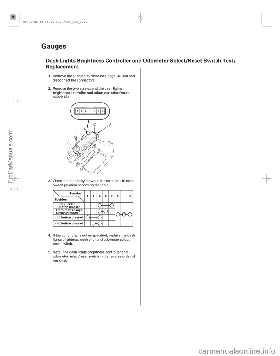
Dash Lights Brightness Controller and Odometer Select/Reset Switch Test/
Replacement
A
Terminal
Position SEL/RESET
button pressed
( ) button pressed km/h-mph change
button pressed
( ) button pressed 12
467
35
1. Remove the subdisplay visor (see page 20-
100) and
disconnect the connectors.
2. Remove the two screws and the dash lights brightness controller and odometer select/reset
switch (A).
3. Check for continuity between the terminals in each switch position according the table.
4. If the continuity is not as specified, replace the dash lights brightness controller and odometer select/
reset switch.
5. Install the dash lights brightness controller and odometer select/reset switch in the r everse order of
removal.
08/08/21 14:36:00 61SNR030_220_0280
ProCarManuals.com
DYNOMITE -2009-
Page 2232 of 2893
����
�µ�µ
�µ
22-282 Reminder Systems
Circuit Diagram
MICU
ORN
(10 A) No. 23
BLK1 2
SRS UNIT
G602
B11
A12
A11 YEL
WHT REDRED")
����
�(�#�'�������������������
�
�����������������)����
�µ�µ
�µ
22-282 Reminder Systems
Circuit Diagram
MICU
ORN
(10 A) No. 23
BLK1 2
SRS UNIT
G602
B11
A12
A11 YEL
WHT REDRED
WHT
ORN28
LT GRN BLK16
G504
INDICATOR DRIVE CIRCUIT
MICU
ECM/PCM MAIN CIRCUIT
21
PNK
124
CAN L
CAN H
CHIME
WHT
BRN
RED 19
1
WHT No. 2 (IG) (50 A)
GAUGE CONTROL MODULE (TACH) 18
17
IG1
BAT
BLU
WHT
UNDER-HOOD FUSE/RELAY BOX
BATTERY IGNITION SWITCH
No. 1 (BAT) (100 A)
(7.5 A) No. 10UNDER-DASH
FUSE/RELAY
BOX
DRIVE
CIRCUIT
PARKING
BRAKE
REMINDER
SEAT
BELT
REMINDER
KEY-IN
REMINDER
F-CAN
TRANSCEIVER B-CAN
TRANSCEIVERLIGHTS-ON
INDICATOR
(LED)
IG1 HOT in ON (II)
and START (III)
ABS MODULATOR-
CONTROL UNIT*1 LIGHTS-ON INDICATOR
DIMMING CIRCUIT
PARKING
BRAKE
SWITCH
(Closed:
Lever pulled)
DRIVER’S
SEAT BELT
BUCKLE
SWITCH
(Closed:
unbuckled) SEAT BELT
REMINDER
INDICATOR
(LED)
BRAKE
SYSTEM
INDICATOR
(LED)COMPULSORY
TURNING-ON
CIRCUIT
LIGHTS-ON
REMINDER
CLIMATE
CONTROL
UNIT
IMMOBILIZER-
KEYLESS
CONTROL UNIT
HANDSFREELINK
CONTROL UNIT*4
H1
D4 D2
Q1 Q9
G2 :CANline
1
VSA MODULATOR-
CONTROL UNIT*2
YAW RATE-LATERAL
ACCELERATION SENSOR*2
DATA LINK CONNECTOR
EPS CONTROL UNIT
TPMS CONTROL UNIT*3 10 V
STABILIZING
CIRCUIT
*1: ’06 07 Touring and Premium models
*2: ’07 TYPE S and ’08 09 models
*3: ’08 09 models
*4: ’09 model with navigation system
MICU
A
B
08/08/21 14:36:02 61SNR030_220_0284
ProCarManuals.com
DYNOMITE -2009-