Page 2141 of 2893

Cavity Wire Test conditionTest: Desired result Possible cause if desired result is
not obtained
22-191
6. Reconnect connectors to the under-dash fuse/relay box, and do these input tests at the following connectors.
If any test indicates a problem, find and correct the cause, then recheck the system.
If all the input tests prove OK, the MICU must be faulty; replace the under-dash fuse/relay box.
G2 ORN Under all conditions Measure the voltage between
terminal G2 and body ground:
There should be battery voltage.Blown No. 23 (10 A) fuse in the
under-hood fuse/relay box
An open in the wire
G6 YEL Under all conditions Measure the voltage between terminal G6 and body ground:
There should be battery voltage.Blown No. 10 (10 A) fuse in the
under-hood fuse/relay box
An open in the wire
E6 BLK Under all conditions Measure the voltage to ground: There should be less than 0.5 V.Poor ground (G602)
An open in the wire
E33 BLK Under all conditions Measure the voltage to ground: There should be less than 0.5 V.Poor ground (G601)
An open in the wire
F20 BLK Under all conditions Measure the voltage to ground: There should be less than 0.5 V.Poor ground (G401)
An open in the wire
T34 BLK Under all conditions Measure the voltage to ground: There should be less than 0.5 V.Poor ground (G501)
An open in the wire
R1 WHT Under all conditions Measure the voltage to ground: There should be battery voltage.Faulty under-dash fuse/relay box
Q11 GRN Hazard warning switch ON Measure the voltage to ground:
There should be battery voltage. Blown No. 23 (10 A) fuse in the
under-hood fuse/relay box
Faulty hazard warning switch
An open in the wire
S18 ·
S5 BRN
·
BLK Turn signal switch in
right position
Measure the voltage between
terminals S18 and S5:
There should be less than 0.5 V. Faulty combination light switch
An open in the wire
Turn signal switch in
left or neutral
position Measure the voltage between
terminals S18 and S5:
There should be 5 V or more. Faulty combination light switch
A short to ground in the wire
S19 ·
S5 LT
GRN ·
BLK Turn signal switch in
left position
Measure the voltage between
terminals S19 and S5:
There should be less than 0.5 V. Faulty combination light switch
An open in the wire
Turn signal switch in
right or neutral
position Measure the voltage between
terminals S19 and S5:
There should be 5 V or more. Faulty combination light switch
A short to ground in the wire
08/08/21 14:27:44 61SNR030_220_0193
ProCarManuals.com
DYNOMITE -2009-
Page 2142 of 2893
���� ���
����
�(�#����������������
����������������� �����)���
22-19222-192 Turn Signal/Hazard Warning Lights
Hazard Warning Switch Test/")
���
����
�����(�#�'���������������
���������
�����
�������)���� ���
����
�(�#�'���������������
����������������� �����)���
22-19222-192 Turn Signal/Hazard Warning Lights
Hazard Warning Switch Test/
Replacement
Side Turn Signal Light Replacement
A
A
Terminal
Position 12
4
5
OFF ON A
A
B
1. Remove the center panel. With audio:– ’06-08 models (see page 23-80)
– ’09 model (see page 23-256)
With navigation: – ’06-08 models (see page 23-155)
– ’09 model (see page 23-355)
2. Remove the screws and the hazard warning switch (A).
3. Check for continuity between the terminals in each switch position according to the table.
4. If the continuity is not as specified, replace the bulb (A) or the hazard warning switch.
5. Install the hazard warning switch in the reverse order of removal. 1. Remove the mirror holder (see page 20-34).
2. Remove the four screws and the mirror visor (A).
3. Disconnect the 2P connector (A) from the side turn
signal light (B), then remove the side turn signal
light.
4. Install the side turn signal light in the reverse order of removal.
08/08/21 14:27:45 61SNR030_220_0194
ProCarManuals.com
DYNOMITE -2009-
Page 2174 of 2893
����
�µ
�µ
�µ
�µ
�µ
�µ �µ
�µ
�µ
�µ
DTC B1077:
YES
NO
YES
NO
YES
NO YES
NO
YES
NO
22-224Wipers/Washers
DTC Troubleshooting
UNDER-DASH F")
���
����
�(�#�'��������� �������������.�
�������������)����
�µ
�µ
�µ
�µ
�µ
�µ �µ
�µ
�µ
�µ
DTC B1077:
YES
NO
YES
NO
YES
NO YES
NO
YES
NO
22-224Wipers/Washers
DTC Troubleshooting
UNDER-DASH FUSE/RELAY BOX CONNECTOR F (34P)
WINDSHIELD WIPER MOTOR 5P CONNECTOR AS (WHT)
AS (WHT)
WINDSHIELD WIPER MOTOR 5P CONNECTOR AS (WHT)
Windshield Wiper (As) Signal
Error
NOTE: If you are troubleshooting multiple DTCs, be
sure to follow the instructions in B-CAN System
Diagnosis Test Mode A (see page 22-93).
1. Clear the DTCs with the HDS.
2. Turn the ignition switch to LOCK (0), and then back to ON (II).
3. Turn the wiper switch to LOW or HIGH for 15 seconds or more, then turn the switch OFF.
Go to step 4.
Go to step 12.
4. Check for DTCs with the HDS.
Go to step 5.
Intermittent failure. The windshield wiper
system is OK at this time. Check for loose or poor
connections.
5. Turn the ignition switch to LOCK (0).
6. Do the wiper motor test (see page 22-231).
Go to step 7.
Replace the windshield wiper motor
(see page 22-233) and recheck.
7. Disconnect under-dash fuse/relay box connector F (34P) and windshield wiper motor 5P connector. 8. Check for continuity between windshield wiper
motor 5P connector terminal No. 5 and under-dash
fuse/relay box connector F (34P) terminal No. 32.
Go to step 9.
Repair an open in the WHT wire.
9. Check for continuity between windshield wiper motor 5P connector terminal No. 5 and body
ground.
Repair a short in the WHT wire.
Go to step 10.
Wire side of female terminals
Wire side of female terminals
Wire side of female terminals
Do t he w i nd shi el d w i per r un? Is DTC B1077 indicated?
Does t he w i per mot or r un nor mal l y and d oes i tpul se? Is there continuity?
Is there continuity?
08/08/21 14:28:46 61SNR030_220_0226
ProCarManuals.com
DYNOMITE -2009-
Page 2209 of 2893
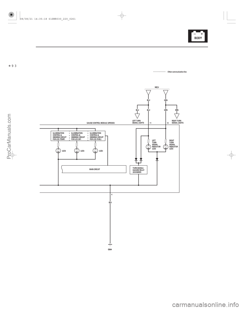
�����
22-259
MICU
BLU GRN
BLU GRN
(LED)
(LED)
(LED)
G504G504 12
BRN
BLU
MAIN CIRCUIT BLK4
GAUGE CONTROL MODULE (SPEEDO) 11
ILLUMINATION
CONTROL &
DIMMING CIRCUIT
FOR LCD (TEMP) ILLUMINATION
CONTROL &
DIMMING CIRCUIT
FOR LCD (SP) ILLUMINATION
CONTROL &
DIMMING CIRCUIT
FOR LCD (FUEL)
LEFT
TURN
SIGNAL
INDICATOR
(LED)RIGHT
TURN
SIGNAL
INDICATOR
(LED)
TURN SIGNAL/
HAZARD RELAY
(SOUNDER) RIGHT TURN
SIGNAL LIGHTS
LEFT TURN
SIGNAL LIGHTS : Other communication line
08/08/21 14:35:18 61SNR030_220_0261
ProCarManuals.com
DYNOMITE -2009-
Page 2211 of 2893
�����
22-261
MICU
BLU GRN
BLU GRN
(LED)
(LED)
(LED)
G504G504 12
BRN
BLU
MAIN CIRCUIT BLK4
GAUGE CONTROL MODULE (SPEEDO) 11
ILLUMINATION
CONTROL &
DIMMING CIRCUIT
FOR LCD (TEMP) ILLUMINATION
CONTROL &
DIMMING CIRCUIT
FOR LCD (SP) ILLUMINATION
CONTROL &
DIMMING CIRCUIT
FOR LCD (FUEL)
LEFT
TURN
SIGNAL
INDICATOR
(LED)RIGHT
TURN
SIGNAL
INDICATOR
(LED)
TURN SIGNAL/
HAZARD RELAY
(SOUNDER) RIGHT TURN
SIGNAL LIGHTS
LEFT TURN
SIGNAL LIGHTS : Other communication line
08/08/21 14:35:19 61SNR030_220_0263
ProCarManuals.com
DYNOMITE -2009-
Page 2225 of 2893

�¦�§ �¦ �§�¦ �§
�¦�§ �¦�§
�¦�§ Cavity Wire Test condition
Test: Desired result Possible cause if desired result
is not obtained
Cavity Wire Test condition Test: Desired result Possible cause if desired result
is not obtained
22-275
4. With the connector still disconnected, do these input tests at the following connector.
If any test indicates a problem, find and correct the cause, then recheck the system.
If all the input tests prove OK, go to step 5.
11 BLU Ignition switch ON,
turn signal switch
in LEFT Measure the voltage to ground:
There should be battery voltage
when the lights are flashing. Faulty MICU
Faulty combination light
switch
An open in the wire
12 GRN Ignition switch ON, turn signal switch
in RIGHT Measure the voltage to ground:
There should be battery voltage
when the lights are flashing. Faulty MICU
Faulty combination light
switch
An open in the wire
7
1 LT GRN
GRY Disconnect the
gauge control
module (tach) 36P
connector Check for continuity between
terminal No. 7 No. 1 and
gauge control module (tach)
36P connector terminal No. 20
No. 2 :
There should be continuity. An open in the wire
Check for continuity between
terminal No. 7 No. 1 and
body ground (gauge control
module (tach) 36P connector
disconnected):
There should be no continuity. A short to ground in the wire
: TYPE S model
5. Reconnect the connector to the gauge control module (speedo), and do these input tests at the following connector.
If any test indicates a problem, find and correct the cause, then recheck the system.
If all the input tests prove OK, the gauge control module (speedo) must be faulty; replace it.
6 WHT Under all
conditions Measure the voltage to ground:
There should be battery voltage. Blown No. 23 (10 A) fuse in
the under-hood fuse/relay
box
An open in the wire
5 BRN Ignition switch ON (II) Measure the voltage to ground:
There should be battery voltage. Blown No. 10 (7.5 A) fuse in
the under-dash fuse/relay box
An open in the wire
4 BLK Under all conditions Measure the voltage to ground:
There should be less than 0.5 V. Poor ground (G504)
An open in the wire
08/08/21 14:35:59 61SNR030_220_0277
ProCarManuals.com
DYNOMITE -2009-
Page 2259 of 2893
����
��������
����
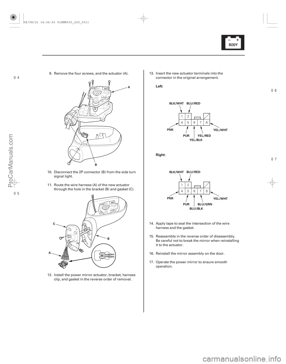
Left:
Right:
22-309
A
B
A B
C BLU/RED
BLK/WHT
YEL/RED
PUR
YEL/BLK YEL/WHT
PNK
BLU/RED
BLK/WHT
BLU/GRN
PUR
BLU/BLK YEL/WHT
PNK
9. Remove the four screws, and the actuator (A).
10. Disconnect the 2P connector (B) from the side turn signal light.
11. Route the wire harness (A) of the new actuator through the hole in the bracket (B) and gasket (C).
12. Install the power mirror actuator, bracket, harness clip, and gasket in the reverse order of removal. 13. Insert the new actuator terminals into the
connector in the original arrangement.
14. Apply tape to seal the intersection of the wire harness and the gasket.
15. Reassemble in the reverse order of disassembly. Be careful not to break the mirror when reinstalling
it to the actuator.
16. Reinstall the mirror assembly on the door.
17. Operate the power mirror to ensure smooth operation.
08/08/21 14:36:53 61SNR030_220_0311
ProCarManuals.com
DYNOMITE -2009-
Page 2265 of 2893
����
22-315
System Description
Mechanical key
(Including transponder) Immobilizer key
MICU
(Imoes circuit) Mechanical key
Steering lock assembly Immob")
���
�(�#�'���������������������������������������)����
22-315
System Description
Mechanical key
(Including transponder) Immobilizer key
MICU
(Imoes circuit) Mechanical key
Steering lock assembly Immobilizer-keyless
control unit
ECM/PCMTransmitter
(Including
transponder)
The vehicle is equipped with a type VI immobilizer system that will disable the vehicle unless a programmed ignition
key is used.
This system consists of a transponder combined with a keyless transmitter, immob
ilizer-keyless control unit, the MICU
(has built-in imoes unit), immobilizer indicator, and the ECM/PCM.
When the immobilizer key (programmed by the HDS) is inserted into the ignition switch and turned to ON (II), the
immobilizer-keyless control unit sends power to the trans ponder in the ignition key. The transponder then sends a
coded signal back to the immobilizer-keyless control unit which then sends a coded signal to the ECM/PCM and the
MICU (imoes unit). The ECM/PCM and MICU (imoes unit) identify this code signal, then fuel power is supplied.
NOTE: The transmitter is automatically programmed to the vehicle when a transponder is programmed by the HDS.
If the wrong key has been used or the code was not received or recognized by the unit, the indicator will come on for
about 2 seconds, then it will blink until the ignition switch is turned to LOCK (0). When the ignition switch is turned to
LOCK (0), the indicator will blink ten times to signal that the unit has reset correctly, then the indicator will go off.
08/08/21 14:36:58 61SNR030_220_0317
ProCarManuals.com
DYNOMITE -2009-