Page 2439 of 2893
���
���
�(�#�'�����#���������
���������������
�������)���� Position Resistance
23-15623-156
Navigation System
Navigation Unit Removal/
Installation (cont’d)
Voice Control Switch Test
A
BC
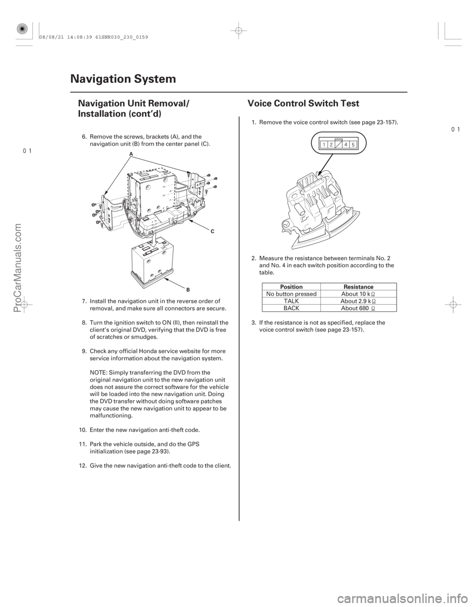
6. Remove the screws, brackets (A), and the
navigation unit (B) from the center panel (C).
7. Install the navigation unit in the reverse order of removal, and make sure all connectors are secure.
8. Turn the ignition switch to ON (II), then reinstall the client’s original DVD, verifying that the DVD is free
of scratches or smudges.
9. Check any official Honda service website for more service information about the navigation system.
NOTE: Simply transferring the DVD from the
original navigation unit to the new navigation unit
does not assure the correct software for the vehicle
will be loaded into the new navigation unit. Doing
the DVD transfer without doing software patches
may cause the new navigation unit to appear to be
malfunctioning.
10. Enter the new navigation anti-theft code.
11. Park the vehicle outside, and do the GPS initialization (see page 23-93).
12. Give the new navigation anti-theft code to the client. 1. Remove the voice control switch (see page 23-157).
2. Measure the resistance between terminals No. 2
andNo.4ineachswitchpositionaccordingtothe
table.
No button pressed About 10 k TALK About 2.9 k
BACK About 680
3. If the resistance is not as specified, replace the voice control switch (see page 23-157).
08/08/21 14:08:39 61SNR030_230_0159
ProCarManuals.com
DYNOMITE -2009-
Page 2440 of 2893
���
���
�(�#�'�����#���������
���������������
�������)���� Position Resistance
23-15623-156
Navigation System
Navigation Unit Removal/
Installation (cont’d)
Voice Control Switch Test
A
BC
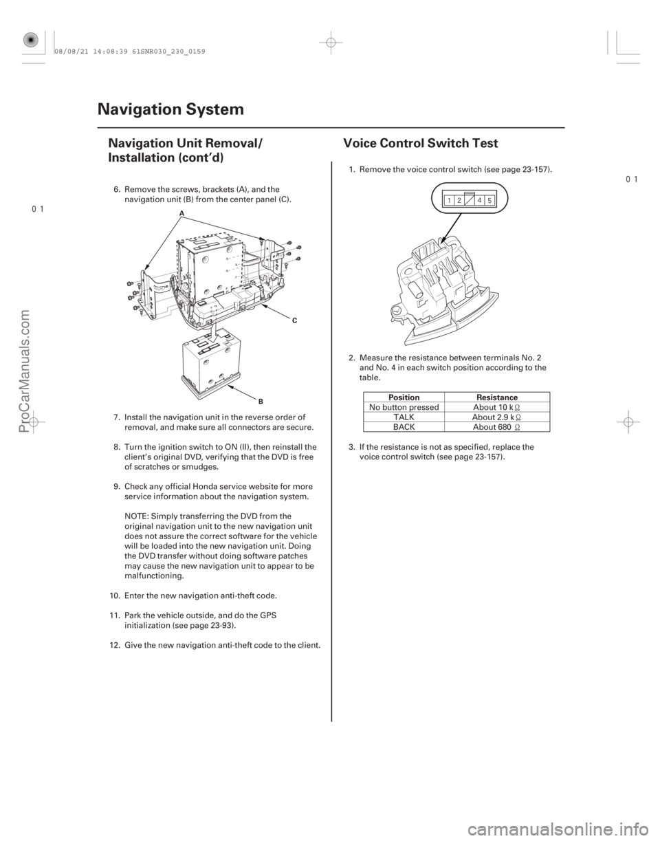
6. Remove the screws, brackets (A), and the
navigation unit (B) from the center panel (C).
7. Install the navigation unit in the reverse order of removal, and make sure all connectors are secure.
8. Turn the ignition switch to ON (II), then reinstall the client’s original DVD, verifying that the DVD is free
of scratches or smudges.
9. Check any official Honda service website for more service information about the navigation system.
NOTE: Simply transferring the DVD from the
original navigation unit to the new navigation unit
does not assure the correct software for the vehicle
will be loaded into the new navigation unit. Doing
the DVD transfer without doing software patches
may cause the new navigation unit to appear to be
malfunctioning.
10. Enter the new navigation anti-theft code.
11. Park the vehicle outside, and do the GPS initialization (see page 23-93).
12. Give the new navigation anti-theft code to the client. 1. Remove the voice control switch (see page 23-157).
2. Measure the resistance between terminals No. 2
andNo.4ineachswitchpositionaccordingtothe
table.
No button pressed About 10 k TALK About 2.9 k
BACK About 680
3. If the resistance is not as specified, replace the voice control switch (see page 23-157).
08/08/21 14:08:39 61SNR030_230_0159
ProCarManuals.com
DYNOMITE -2009-
Page 2468 of 2893
������(�#�'�����#�����
���������������������������)����
�µ�´
�µ
�´
�´
�´
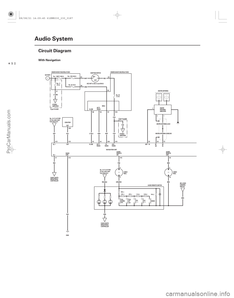
With Navigation
23-184Audio System
Circuit Diagram
3
G2 21 G1
SCTY
RADIO
K-LINE
PUR
PUR
UNDER-DASH FUSE/RELAY BOX
AM/FM ANTENNA
UNDER-HOOD FUSE/RELAY BOX
() ()AM/FM ANTENNA LEAD
AM/FM ANTENNA SUBLEAD
G3
ILL A1
RED RADIO ACC
SCTY
RADIO
K-LINE Q8 Q4 Q1 Q14
LT BLU A3 A4 GRN WHT
A24
VSP
ECM/PCM
BLU A14
PUR
MICU
ACC HOT in ACC (I) and ON (II)
ORN RED
WHT
ACC
BAT
IGNITION SWITCH
No. 23 (10 A)
No. 2 (IG) (50 A)
BATTERY
No. 1 (BAT) (100 A)
A13 A15
ILL
NAVIGATION UNIT
GRY
ANT B
10 k
1.2 k
470
270
100
CH
( DOWN VOL VOL UP
( MODEBRN
A5
BRN
3.9 k
)
) CH
RED/BLK GRN/RED A16
PNK
GRN SW REMOTE AUDIO
AUDIO
REMOTE
GND
9 4 3
10
AUDIO REMOTE SWITCH
BLK
G505
GND RADIO
A12
No.14(7.5A)FUSE
(In the under-dash
fuse/relay box)
DASH LIGHTS
BRIGHTNESS
CONTROLLER AM/FM
ANTENNA
AMPLIFIER
No.14(7.5A)FUSE
(In the under-dash
fuse/relay box) CABLE
REEL CABLE
REEL
DASH LIGHTS
BRIGHTNESS
CONTROLLER STEREO
AMPLIFIER
LT GRN
STEREO
AMPLIFIER No. 17
(15 A)
D1
D4 C2
G2 No. 35
(7.5 A)
(Type S model)
VSPA29 (Type S model)
RADIO B
BRN
HFL-VOICE
CONTROL
SWITCH
J3
RF
SHRF
IN
2
1
08/08/21 14:09:45 61SNR030_230_0187
ProCarManuals.com
DYNOMITE -2009-
Page 2472 of 2893
������(�#�'�����#� ���
���������������������������)����
�µ�´
�µ
�´
�´
�´
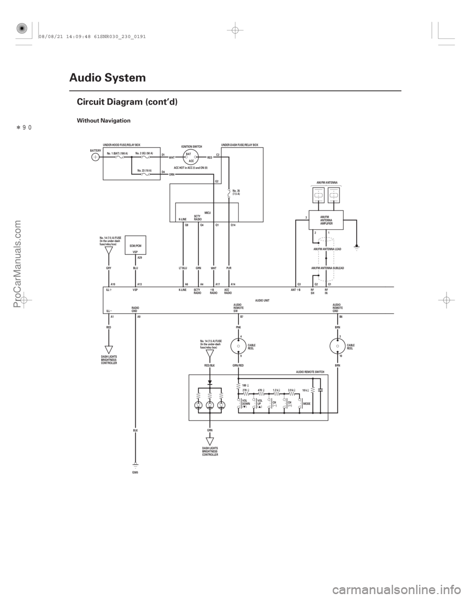
Without Navigation
23-188Audio System
Circuit Diagram (cont’d)
3
G2 21 G1
SCTY
RADIO
K-LINE UNDER-DASH FUSE/RELAY BOX
AM/FM ANTENNA
UNDER-HOOD FUSE/RELAY BOX
() ()AM/FM ANTENNA LEAD
AM/FM ANTENNA SUBLEAD
G3
ILL A1
RED RADIO ACC
SCTY
RADIO
K-LINE Q8 Q4 Q1 Q14
LT BLU A6 A4 GRN
WHT
A17
VSP
ECM/PCM
BLU A14
PUR
MICU
ACC HOT in ACC (I) and ON (II)
ORN RED
WHT
ACC
BAT
IGNITION SWITCH
No. 23 (10 A)
No. 2 (IG) (50 A)
BATTERY
No. 1 (BAT) (100 A)
A10 A13
ILL GRY
ANT B
10 k
1.2 k
470
270
100
CH
( DOWN VOL VOL UP
( MODEBRN
B6
BRN
3.9 k
)
) CH
RED/BLK GRN/RED B7
PNK
GRN SW REMOTE
AUDIO
AUDIO
REMOTE
GND
9 4 3
10
AUDIO REMOTE SWITCH
BLK
G505
GND RADIO
A9
No.14(7.5A)FUSE
(In the under-dash
fuse/relay box)
DASH LIGHTS
BRIGHTNESS
CONTROLLER AM/FM
ANTENNA
AMPLIFIER
No.14(7.5A)FUSE
(In the under-dash
fuse/relay box) CABLE
REEL CABLE
REEL
DASH LIGHTS
BRIGHTNESS
CONTROLLER
D1
D4
C2
G2 No. 35
(7.5 A)
VSP A29
RADIOB
RF
SHRF
IN
AUDIO UNIT
08/08/21 14:09:48 61SNR030_230_0191
ProCarManuals.com
DYNOMITE -2009-
Page 2474 of 2893
����
������(�#�'�����#� ���
���������������������������)����
Without Navigation
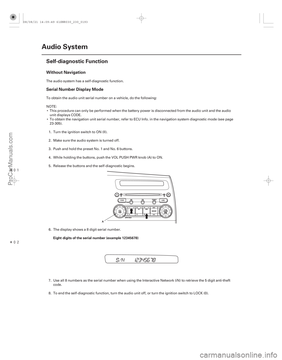
Serial Number Display Mode
Eight digits of the serial number (example 12345678)
23-190Audio System
Self-diagnostic Function
A
The audio system has a self-diagnostic function.
To obtain the audio unit serial number on a vehicle, do the following:
NOTE:
This procedure can only be performed when the battery power is disconnected from the audio unit and the audio unit displays CODE.
To obtain the navigation unit serial number, refer to ECU Info. in the navigation system diagnostic mode (see page 23-305).
1. Turn the ignition switch to ON (II).
2. Make sure the audio system is turned off.
3. Push and hold the preset No. 1 and No. 6 buttons.
4. While holding the buttons, push the VOL PUSH PWR knob (A) to ON.
5. Release the buttons and the self-diagnostic begins.
6. The display shows a 8 digit serial number.
7. Use all 8 numbers as the serial number when using the Interactive Network (iN) to retrieve the 5 digit anti-theft code.
8. To end the self-diagnostic function, turn the audio unit off, or turn the ignition switch to LOCK (0).
08/08/21 14:09:49 61SNR030_230_0193
ProCarManuals.com
DYNOMITE -2009-
Page 2475 of 2893
�����
How to check for audio system condition
No. 3 button
No. 4 button
No. 5 button
FM button (Push and hold 5 sec.)
CD button (Push and hold 5 sec.)
23-191
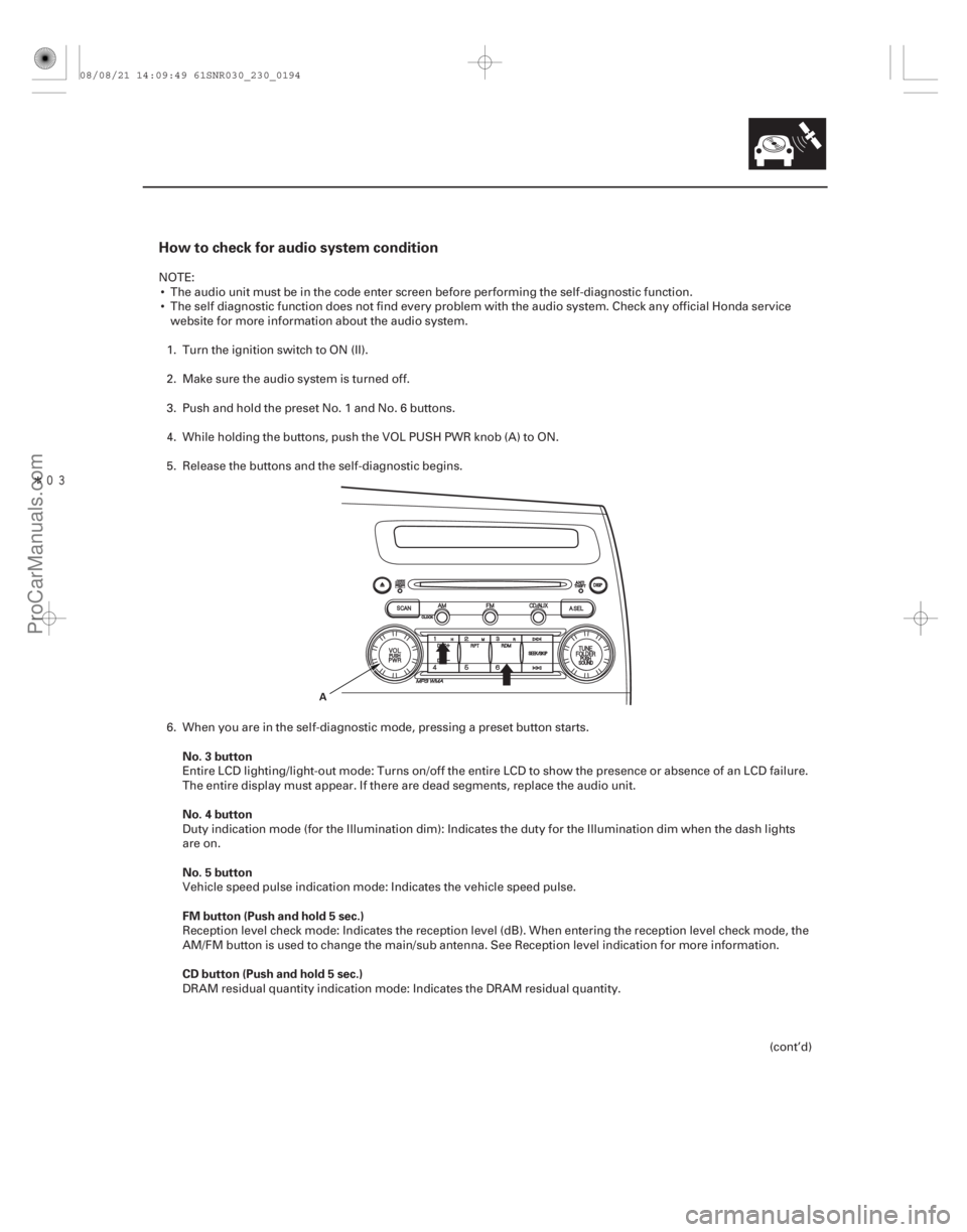
A
NOTE: The audio unit must be in the code enter screen before performing the self-diagnostic function.
The self diagnostic function does not find every problem with the audio system. Check any official H onda service
website for more information about the audio system.
1. Turn the ignition switch to ON (II).
2. Make sure the audio system is turned off.
3. Push and hold the preset No. 1 and No. 6 buttons.
4. While holding the buttons, push the VOL PUSH PWR knob (A) to ON.
5. Release the buttons and the self-diagnostic begins.
6. When you are in the self-diagnostic mode, pressing a preset button starts.
Entire LCD lighting/light-out mode: Turns on/off the entire LCD to show the presence or absence of an LCD failure.
The entire display must appear. If there are dead segments, replace the audio unit.
Duty indication mode (for the Illumination dim): Indicates the duty for the Illumination dim when the dash lights
are on.
Vehicle speed pulse indication mode: Indicates the vehicle speed pulse.
Reception level check mode: Indicates the reception level (dB). When entering the reception level check mode, the
AM/FM button is used to change the main/sub antenna. See Reception level indication for more information.
DRAM residual quantity indication mode: Indicates the DRAM residual quantity.
(cont’d)
08/08/21 14:09:49 61SNR030_230_0194
ProCarManuals.com
DYNOMITE -2009-
Page 2476 of 2893
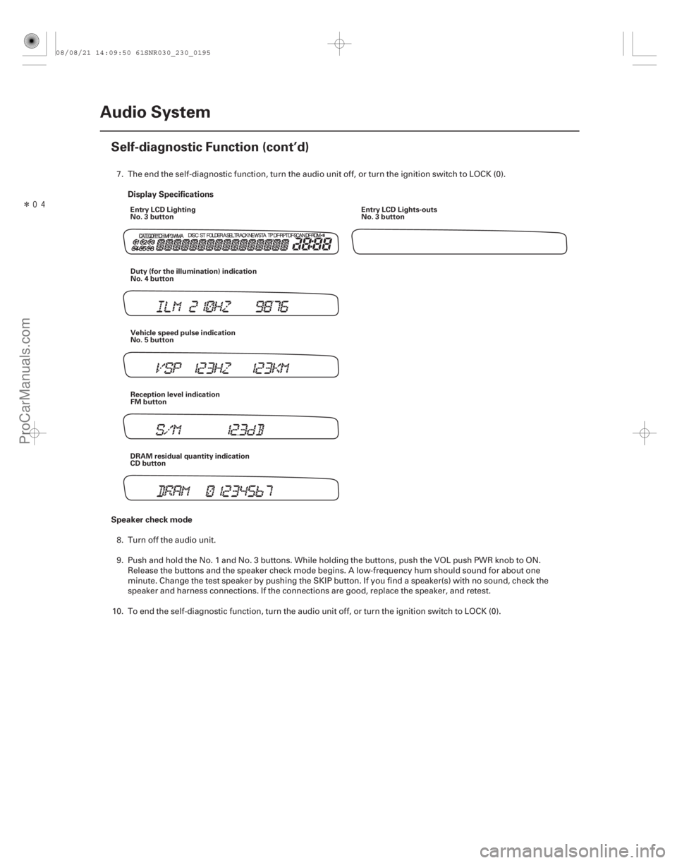
�����Display Specifications
Speaker check mode
23-192 Audio System
Self-diagnostic Function (cont’d)
Entry LCD Lighting
No. 3 button
Entry LCD Lights-outs
No. 3 button
Duty (for the illumination) indication
No. 4 button
Vehicle speed pulse indication
No. 5 button
Reception level indication
FM button
DRAM residual quantity indication
CD button
7. The end the self-diagnostic function, turn the audio unit off, or turn the ignition switch to LOCK (0).
8. Turn off the audio unit.
9. Push and hold the No. 1 and No. 3 buttons. While holding the buttons, push the VOL push PWR knob to ON. Release the buttons and the speaker check mode begins. A low-frequency hum should sound for about one
minute. Change the test speaker by pushing the SKIP button. If you find a speaker(s) with no sound, check the
speaker and harness connections. If the connections are good, replace the speaker, and retest.
10. To end the self-diagnostic function, turn the audio unit off, or turn the ignition switch to LOCK (0).
08/08/21 14:09:50 61SNR030_230_0195
ProCarManuals.com
DYNOMITE -2009-
Page 2477 of 2893
Reception level indication mode
Preperation:
23-193
This diagnostic screen checks the audio unit’s reception level. This level then can be used in the diagnosis of audio
unit reception quality. The reception level is displayed in decibels (dB)
Pank the vehicle putdoors in an appropriate location for good radio reception.
Tune to a powerful local FM radio station then write down the radio station number. 1. Enter the reception level indication mode in the self-dia gnostic function. The AM/FM antenna amplifier is on (A.
SEL or TP is not displayed in the audio-HVAC display).
2. Tune to the FM radio station you wrote down preperation using the T UNING knob, and note the decibel level of
that station when you release the button.
3. Press and release the A. SEL button to turn the AM/FM antenna amplifier off (A. SEL or TP is now displayed in the audio-HVAC display).
4. Tune to the FM radio station you wrote down in preperation using the T UNING knob, and note the decibel level of
that station when you release the button.
5. Press and release the A. SEL button to turn the AM/FM antenna amplifier back on (A. SEL or TP is not displayed in the audio-HVAC display.
6. Turn the ignition switch to LOCK (0) or audio unit off to exit the test mode.
7. Compare your results to a known-good, (make sure it is the same year and trim level) in the same location and
direction, and under the same environmental conditions.
08/08/21 14:09:50 61SNR030_230_0196
ProCarManuals.com
DYNOMITE -2009-