Page 2059 of 2893
����
�(�#�'���������������������������������������)����
22-112Keyless/Power Door Locks/Security System
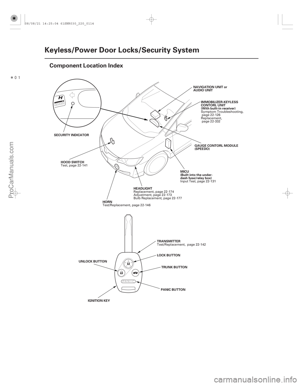
Component Location Index
NAVIGATION UNIT or
AUDIO UNIT
IMMOBILIZER-KEYLESS
CONTORL UNIT
(With built-in receiver)
SECURITY INDICATOR GAUGE CONTORL MODULE
(SPEEDO)
HEADLIGHT
HOOD SWITCH
MICU
(Built into the under-
dash fuse/relay box)
HORN
TRANSMITTER
LOCK BUTTON TRUNK BUTTON
UNLOCK BUTTON
IGNITION KEY PANIC BUTTONSymptom Troubleshooting,
page 22-126
Replacement, page 22-332
Replacement, page 22-174
Adjustment, page 22-173
Bulb Replacement, page 22-177
Test, page 22-141
Input Test, page 22-131
Test/Replacement, page 22-146
Test/Replacement, page 22-142
08/08/21 14:25:04 61SNR030_220_0114
ProCarManuals.com
DYNOMITE -2009-
Page 2060 of 2893
 DRIVER’S DOOR LOCK
ACTUATO")
�����
�����
22-113
LEFT REAR DOOR LOCK
ACTUATOR/
KNOB SWITCHDRIVER’S DOOR KEY CYLINDER SWITCH
DRIVER’S DOOR LOCK SWITCH
(Built into the power
window master switch) DRIVER’S DOOR LOCK
ACTUATOR/
KNOB SWITCH TRUNK LID RELEASE ACTUATOR/
LATCH SWITCH
LEFT REAR DOOR SWITCH IGNITION KEY SWITCH
DRIVER’S DOOR
SWITCH
RIGHT REAR DOOR LOCK
ACTUATOR/KNOB SWITCHFRONT PASSENGER’S
DOOR SWITCHFRONT PASSENGER’S DOOR
LOCK ACTUATOR/KNOB SWITCH
FRONT PASSENGER’S
DOOR LOCK SWITCH
RIGHT REAR DOOR SWITCH
LICENSE PLATE LIGHTS
INNER TAILLIGHTTAILLIGHTActuator Test,
page 22-137
Knob Switch Test,
page 22-138 Test, page 22-140
Replacement, page 20-9
Test, page 22-139 Acutuator Test,page 22-137
Knob Switch Test, page 22-138 Actuator Test, page 22-141
Latch Switch Test, page 22-200
Test, page 22-207
Actuator Test, page 22-137
Knob Switch Test, page 22-138 Actuator Test, page 22-137
Knob Switch Test, page 22-138
Test, page 22-139
Replacement, page 22-139
Replacement, page 22-180
Replacement,page 22-179
Replacement, page 22-179
08/08/21 14:25:08 61SNR030_220_0115
ProCarManuals.com
DYNOMITE -2009-
Page 2061 of 2893
����
Security Alarm System
22-114Keyless/Power Door Locks/Security System
System Description
The security alarm system is armed automatically after the do")
�(�#�'���������������������������������������)����
Security Alarm System
22-114Keyless/Power Door Locks/Security System
System Description
The security alarm system is armed automatically after the doors, hood, and trunk are closed and locked. For the
system to arm, the ignition switch must be to LOCK (0), the key must be removed from the ignition switch, and the
MICU must receive signals that the doors, hood, and trunk are closed and locked. The alarm can be disarmed at any
time by unlocking the driver’s door with the key or pressing the UNLOCK button on the transmitter.
When everything is closed and locked, the only i
nputs that are grounded, and have 0 V, are the driver’s door lock knob
switch (LOCK position), and the audio unit or navigation unit (if equipped). In other words, all of the other switches are
open, and have about 10 to 12 V, including the key cylinder switches. The security indicator in the gauge control
module (speedo) begins to flash immediately after the vehicle is completely closed and locked, and 15 seconds later,
the security system arms. If the security indicator does not flash, the system is not arming. A beep sounds and parking
lights flash to confirm the security alarm system is armed if the LOCK button is pressed a second time within
5 seconds.
If one of the switches is misadjusted or shorted internally, or there is a short in the circuit, the security system will not
arm. As long as the control unit continues to receive a ground signal (0 V), it senses that the vehicle is not closed and
locked, and the system will not arm. A switch that is slightly misadjusted can cause the alarm to sound for no apparent
reason. In this case, a significant change in outside air temperature, the vibration of a passing truck, or someone
bumping into the vehicle could cause the alarm to sound. There is no glass breakage or motion detector feature.
If anything is opened or improperly unlocked after the system is armed, the control unit receives a ground signal from
that switch, and the 10 to 12 V reference drops to 0 V. If the audio unit or navigation unit (if equipped) is disconnected,
the input loses its ground, and the input voltage goes to 10 to 12 V. The system sounds the alarm when any of these
occur:
A door or the trunk is forced open.
A door is unlocked without using the key or the transmitter.
The hood is opened.
The audio unit or navigation unit (if equipped) is disconnected.
The transmitter PANIC button is pressed.
When the system sounds the alarm, the horn sounds and the exterior lights flash for 2 minutes. The alarm can be
stopped at any time by unlocking the driver’s door with the key or by pressing any button on the transmitter.
08/08/21 14:25:08 61SNR030_220_0116
ProCarManuals.com
DYNOMITE -2009-
Page 2062 of 2893

Panic Mode
Keyless Entry System
22-115
The panic mode sounds the alarm in order to attract attention. When the PANIC button on the transmitter is pressed
and held for 2 seconds, the horn sounds and the exterior lights flash for about 20 seconds.
The panic mode can be cancelled at anytime by pressing any button on the transmitter or by turning the ignition
switch to ON (II). The panic mode will not function if the ignition switch is to ON (II).
The keyless entry system is integrated with the multiplex integrated control system. The multiplex integrated control
unit (MICU) receives LOCK, UNLOCK and PANIC signals from the immobilizer-keyless control unit (keyless receiver).
The keyless entry system allows you to lock and unlock the vehicle with the transmitter.
When the switch for the ceiling light is in the center (DOOR) position, it will come on when the UNLOCK button is
pressed. If a door is not opened, the light will go off in about 30 seconds, and the doors will relock. If the doors are
locked with the transmitter within 30 seconds, the light will go off immediately.
08/08/21 14:25:09 61SNR030_220_0117
ProCarManuals.com
DYNOMITE -2009-
Page 2063 of 2893
������(�#�'���������������������������������������)����
�´
22-116Keyless/Power Door Locks/Security System
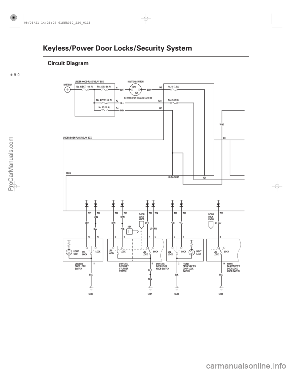
Circuit Diagram
Q1
G2
G21 D2
ORN
GRN
BRN
G503 G501 G504 G504 IG1 HOT in ON (II) and START (III)
8 T22
LT BLU
BLK10LOCK
LOCK
YEL
T30
1
6
PUR
T29
BLK 2
11
BLK
T27
GRY
19 17 T28
BLU
LOCK LOCK
KEY
MICU No. 25 (20 A)
ORN
IG1
5
BLK
No. 23 (10 A)
T24
LT GRN 6
UNDER-DASH FUSE/RELAY BOX
WHTT23
7
LOCK
PNK
T32
9
8
BRN
T31 No. 10 (7.5 A)
BLU
IGNITION SWITCH
IG1
BAT
BLU
WHT
No. 4 (P/W) (40 A)
BATTERY
No. 1 (BAT) (100 A) No. 2 (IG) (50 A)
UNDER-HOOD FUSE/RELAY BOX
UN-
LOCKUN-
LOCK
UN-
LOCK
DRIVER’S
DOOR LOCK
SWITCH DRIVER’S
DOOR KEY
CYLINDER
SWITCHDRIVER’S
DOOR LOCK
KNOB SWITCH
DOOR
LOCK
KNOB
DOOR
LOCK
KNOB
FRONT
PASSENGER’S
DOOR LOCK
KNOB SWITCH
FRONT
PASSENGER’S
DOOR LOCK
SWITCH
UN-
LOCK
UN-
LOCK
LIGHT
(LED)
LIGHT
(LED)
H1
K2
D4
BBACKUPWHT
08/08/21 14:25:09 61SNR030_220_0118
ProCarManuals.com
DYNOMITE -2009-
Page 2064 of 2893
�����
22-117
UART
UART
MAIN CIRCUIT
PNK PNK 20*1
21
LT GRN*1
T34 E6
G501 BLK
SG
BLK
G602 PG
F20
E33
G601 BLK BLK
G401 YEL
BLU
BLU
BLU
B-CAN
M10
E21E31
BLU
E1 E14
YEL
43 1
2 N7
YEL M8
4
BLU 3
N13
1
BLU 2
YEL A
MICU
1
Q6 4
PNK
WHT
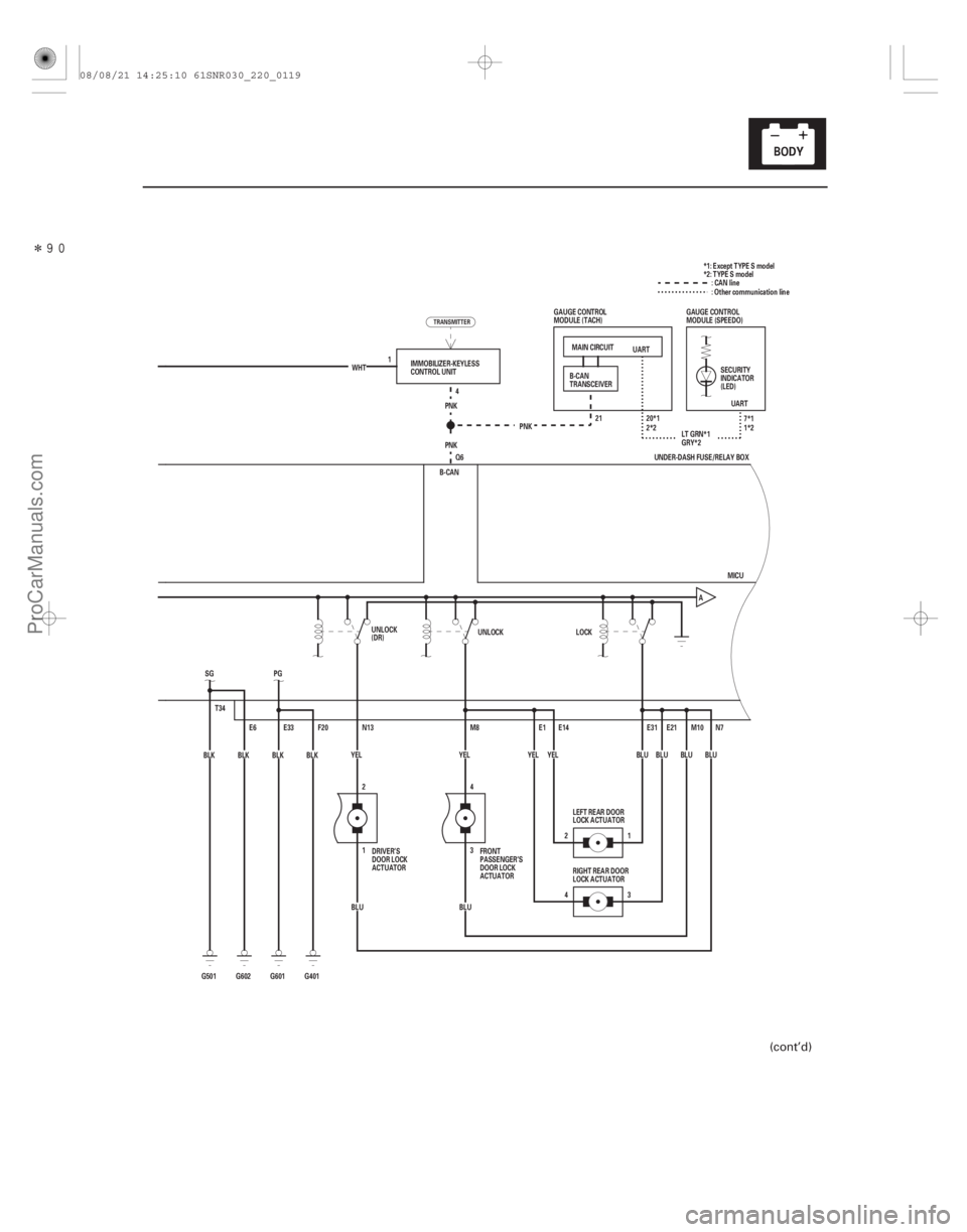
IMMOBILIZER-KEYLESS
CONTROL UNIT
DRIVER’S
DOOR LOCK
ACTUATOR FRONT
PASSENGER’S
DOOR LOCK
ACTUATORLEFT REAR DOOR
LOCK ACTUATOR
RIGHT REAR DOOR
LOCK ACTUATOR SECURITY
INDICATOR
(LED)
B-CAN
TRANSCEIVER
GAUGE CONTROL
MODULE (TACH)
GAUGE CONTROL
MODULE (SPEEDO):CANline
2*2 7*1
1*2
GRY*2 *1: Except TYPE S model
*2: TYPE S model
: Other communication line
UNDER-DASH FUSE/RELAY BOX
UNLOCK
(DR) UNLOCK
LOCK
TRANSMITTER
(cont’d)
08/08/21 14:25:10 61SNR030_220_0119
ProCarManuals.com
DYNOMITE -2009-
Page 2065 of 2893
����
22-118Keyless/Power Door Locks/Security System
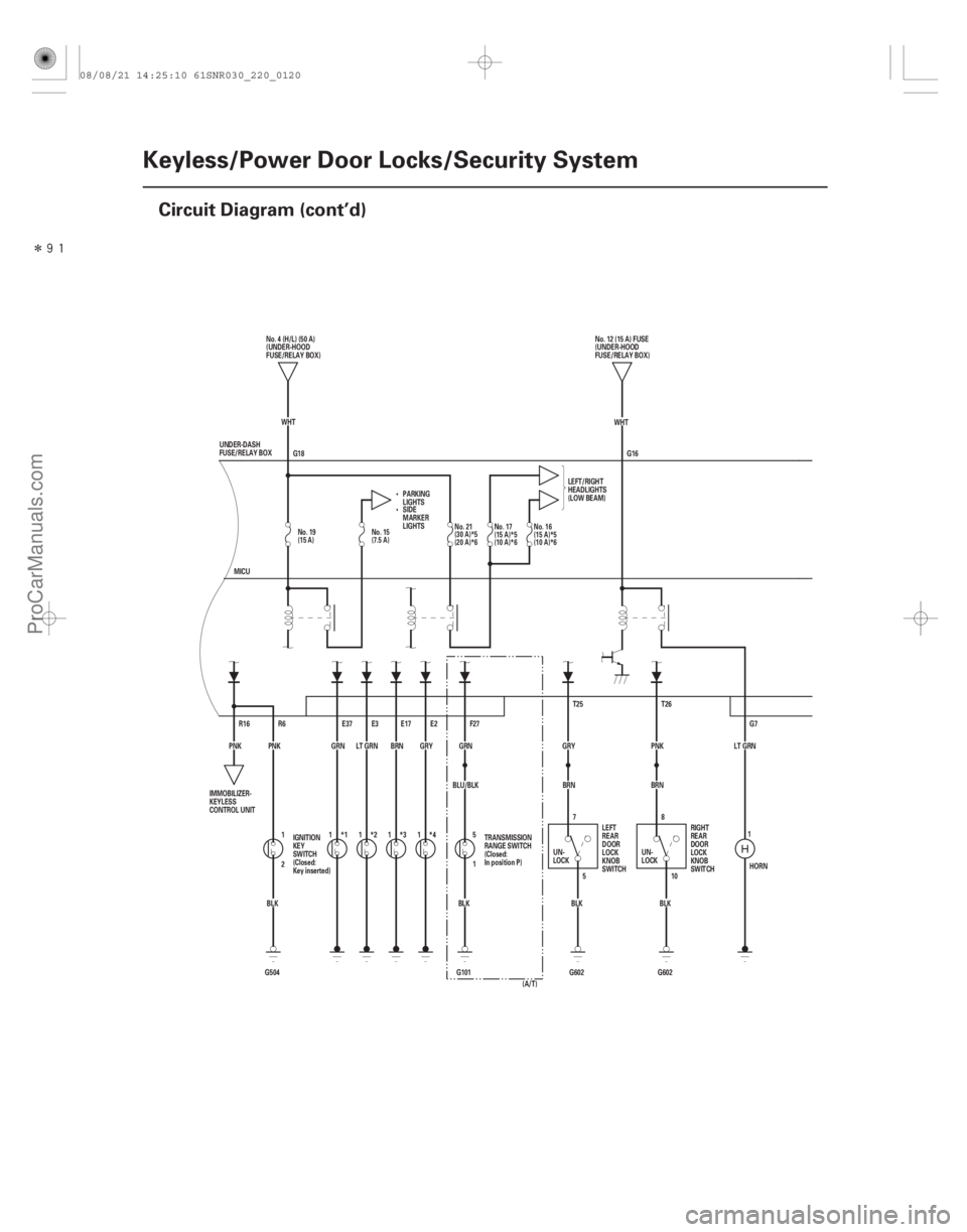
Circuit Diagram (cont’d)
G18
HORN
LT GRN
G7
G16
T26
PNK
BRN
G602BLK8
10
5
7
BLK
G602
BRN
GRY T25
BLU/BLK GRN
F27
5
1
BLK
G101
E2
GRY
*4
E17
BRN
*3
E3
LT GRN
*2
*1
GRN
E37
G504 BLK
2 1
PNK
R6
PNK R16 WHT
WHT
MICU No. 4 (H/L) (50 A)
(UNDER-HOOD
FUSE/RELAY BOX)
PARKING
LIGHTS LEFT/RIGHT
HEADLIGHTS
(LOW BEAM)
UNDER-DASH
FUSE/RELAY BOX No. 12 (15 A) FUSE
(UNDER-HOOD
FUSE/RELAY BOX)
IMMOBILIZER-
KEYLESS
CONTROL UNIT IGNITION
KEY
SWITCH
(Closed:
Key inserted) TRANSMISSION
RANGE SWITCH
(Closed:
In position P)
UN-
LOCKLEFT
REAR
DOOR
LOCK
KNOB
SWITCH RIGHT
REAR
DOOR
LOCK
KNOB
SWITCH
UN-
LOCK
SIDE
MARKER
LIGHTS
(A/T)
1111
1
No. 19
(15 A)No. 15
(7.5 A) No. 21
(30 A)*5
(20 A)*6No. 17
(15 A)*5
(10 A)*6No. 16
(15 A)*5
(10 A)*6
08/08/21 14:25:10 61SNR030_220_0120
ProCarManuals.com
DYNOMITE -2009-
Page 2067 of 2893
����
�µ
�µ
�µ
�µ �µ
�µ
�µ
�µ
DTC B1026:
YES
NO
YES
NO YES
NO
YES
NO
22-120Keyless/Power Door Locks/Security System
DTC Troubleshooting
FRONT")
���
�(�#�'��������� �������������.�
�������������)����
�µ
�µ
�µ
�µ �µ
�µ
�µ
�µ
DTC B1026:
YES
NO
YES
NO YES
NO
YES
NO
22-120Keyless/Power Door Locks/Security System
DTC Troubleshooting
FRONT PASSENGER’S POWER
WINDOW SWITCH 8P CONNECTOR
LOCK (YEL)
UNLOCK (PUR)
Front Passenger’s Door Lock
Switch Signal Error
NOTE: If you are troubleshooting multiple DTCs, be
sure to follow the instructions in B-CAN System
Diagnosis Test Mode A (see page 22-93).
1. Clear the DTCs with the HDS.
2. Turn the ignition switch to LOCK (0), and then back to ON (II).
3. Operate the front passenger’s door lock switch several times.
4. Check for DTCs with the HDS.
Go to step 5.
Intermittent failure. The front passenger’s
door lock system is OK at this time.
5. With the front passenger’s door lock switch in the neutral position, select KEYLESS from the HDS and
enter the DATA LIST.
6. Check the ON/OFF information of the FRONT PASSENGER’S DOOR LOCK SWITCH (LOCK) and
FRONT PASSENGER’S DOOR LOCK SWITCH
(UNLOCK) in the DATA LIST.
Go to step 12.
Go to step 7. 7. Disconnect the front passenger’s power window
switch 8P connector.
8. Check the ON/OFF information of the FRONT PASSENGER’S DOOR LOCK SWITCH (LOCK) and
FRONT PASSENGER’S DOOR LOCK SWITCH
(UNLOCK) in the DATA LIST.
Faulty door lock switch; replace the front
passenger’s power window switch (see page
22-220).
Go to step 9.
9. Turn the ignition switch to LOCK (0).
10. Disconnect under-dash fuse/relay box connector T (34P).
11. Check for continuity between front passenger’s power window switch 8P connector terminals No. 1
(LOCK) and No. 6 (UNLOCK) and body ground.
Repair a short in the LOCK or UNLOCK
wire.
Faulty MICU, replace the under-dash fuse/
relay box (see page 22-66).
Wire side of female terminals
Is DTC B1026 indicated?
Ar e bot h i nf or mat i on i nd i cat or s OF F ? Ar e bot h i nf or mat i on i nd i cat or s OF F ?
Is there continuity?
08/08/21 14:26:01 61SNR030_220_0122
ProCarManuals.com
DYNOMITE -2009-