Page 1861 of 5135
100FR±01
A79186
±
ENGINE CONTROL SYSTEM ECM
10±65
AVENSIS REPAIR MANUAL (RM1018E)
ECM
REPLACEMENT
HINT:
1CD±FTV Engine Type:
Each injector assembly has a characteristic fuel injecting behavior. The ECM stores compensation codes
which are used to optimize fuel injection for the injectors. When replacing t\
he ECM, the compensation codes
must be set to the new ECM.
1.REMOVE GLOVE COMPARTMENT DOOR ASSY (See page 71±11)
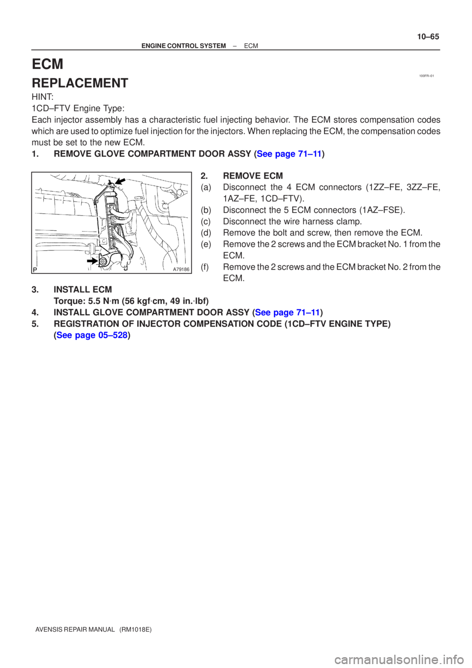
2.REMOVE ECM
(a)Disconnect the 4 ECM connectors (1ZZ±FE, 3ZZ±FE,1AZ±FE, 1CD±FTV).
(b)Disconnect the 5 ECM connectors (1AZ±FSE).
(c)Disconnect the wire harness clamp.
(d)Remove the bolt and screw, then remove the ECM.
(e)Remove the 2 screws and the ECM bracket No. 1 from the ECM.
(f)Remove the 2 screws and the ECM bracket No. 2 from the ECM.
3.INSTALL ECM Torque: 5.5 N �m (56 kgf �cm, 49 in. �lbf)
4.INSTALL GLOVE COMPARTMENT DOOR ASSY (See page 71±11)
5.REGISTRATION OF INJECTOR COMPENSATION CODE (1CD±FTV ENGINE TYPE) (See page 05±528)
Page 2046 of 5135
A77338
A79320
A79296
A60622
14±30
±
ENGINE MECHANICAL PARTIAL ENGINE ASSY (1ZZ±FE/3ZZ±FE)
AVENSIS REPAIR MANUAL (RM1018E)
32. SEPARATE FLOOR SHIFT CABLE TRANSMISSION CONTROL SELECT (M/T TRANSAXLE) (See page 41±15)
33. SEPARATE FLOOR SHIFT CABLE TRANSMISSION CONTROL SHIFT (M/T TRANSAXLE)
(See page 41±15)
34. SEPARATE FLOOR SHIFT CABLE TRANSMISSION CONTROL SHIFT (A/T TRANSAXLE) (See page 40±11)
35.SEPARATE CLUTCH RELEASE CYLINDER ASSY (M/T TRANSAXLE) (See page 41±15)
36.REMOVE GLOVE COMPARTMENT DOOR ASSY (See page 71±11)
37. REMOVE INSTRUMENT PANEL UNDER COVER SUB±ASSY NO.2
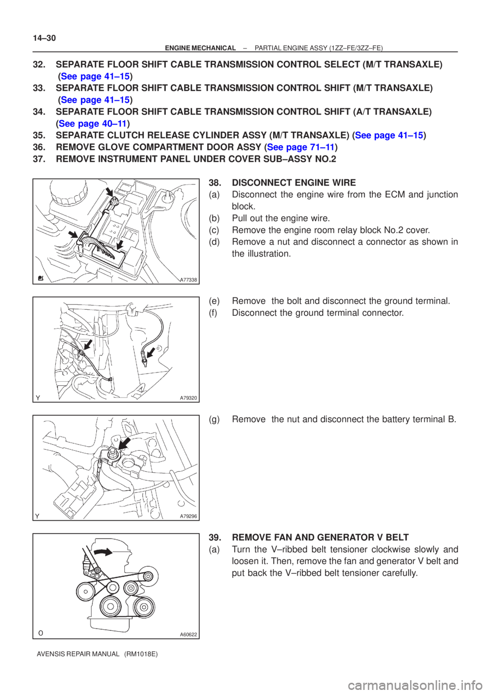
38. DISCONNECT ENGINE WIRE
(a) Disconnect the engine wire from the ECM and junctionblock.
(b) Pull out the engine wire.
(c) Remove the engine room relay block No.2 cover.
(d) Remove a nut and disconnect a connector as shown in the illustration.
(e) Remove the bolt and disconnect the ground terminal.
(f) Disconnect the ground terminal connector.
(g) Remove the nut and disconnect the battery terminal B.
39. REMOVE FAN AND GENERATOR V BELT
(a) Turn the V±ribbed belt tensioner clockwise slowly and loosen it. Then, remove the fan and generator V belt and
put back the V±ribbed belt tensioner carefully.
Page 2047 of 5135
A64005
±
ENGINE MECHANICAL PARTIAL ENGINE ASSY (1ZZ±FE/3ZZ±FE)
14±31
AVENSIS REPAIR MANUAL (RM1018E)
40.REMOVE GENERATOR ASSY (See page 19±7)
41. SEPARATE COMPRESSOR AND MAGNETIC CLUTCH (W/ AIR CONDITIONING)
HINT:
�Secure the compressor and hoses off to the side instead of discharging the A/C system.
�1ZZ±FE (See page 55±74)
�3ZZ±FE (See page 55±70)
42. REMOVE COLUMN HOLE COVER SILENCER SHEET
(a) Remove the 2 clips and the column hole cover silencer sheet.
43.SEPARATE STEERING INTERMEDIATE SHAFT (See page 50±9)
44.REMOVE FRONT DOOR SCUFF PLATE RH (See page 71±11)
45.REMOVE COWL SIDE TRIM BOARD RH (See page 71±11)
46. REMOVE FRONT FLOOR FOOTREST
47. REMOVE FLOOR PANEL BRACE FRONT
(a) Remove the 2 nuts and the floor panel brace front.
48.REMOVE EXHAUST PIPE ASSY FRONT (See page 15±2)
49.REMOVE FRONT AXLE HUB LH NUT (See page 30±6)
SST 09930±00010
50. REMOVE FRONT AXLE HUB RH NUT SST 09930±00010
HINT:
Perform the same procedure as above on the opposite side.
51.SEPARATE TIE ROD END SUB±ASSY LH (See page 30±6)
SST 09628±62011
52. SEPARATE TIE ROD END SUB±ASSY RH SST 09628±62011
HINT:
Perform the same procedure as above on the opposite side.
53.SEPARATE FRONT STABILIZER LINK ASSY LH (See page 30±6)
54. SEPARATE FRONT STABILIZER LINK ASSY RH
HINT:
Perform the same procedure as above on the opposite side.
55.SEPARATE FRONT SUSPENSION ARM SUB±ASSY LOWER NO.1 LH (See page 30±6)
56. SEPARATE FRONT SUSPENSION ARM SUB±ASSY LOWER NO.1 RH
HINT:
Perform the same procedure as above on the opposite side.
57.SEPARATE FRONT AXLE ASSY LH (See page 30±6)
58. SEPARATE FRONT AXLE ASSY RH
HINT:
Perform the same procedure as above on the opposite side.
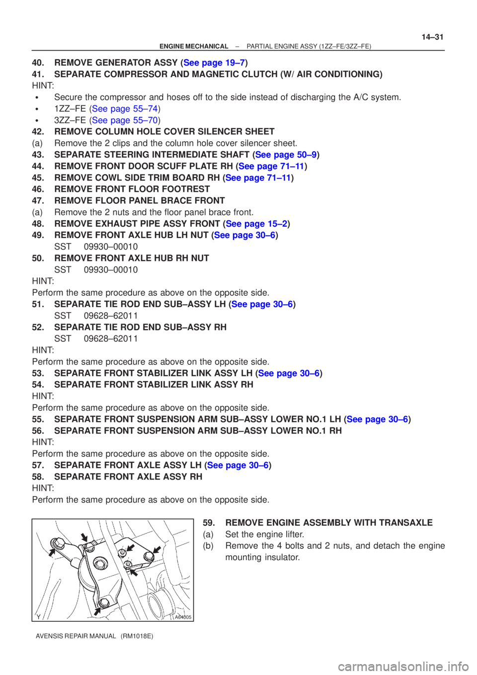
59. REMOVE ENGINE ASSEMBLY WITH TRANSAXLE
(a) Set the engine lifter.
(b) Remove the 4 bolts and 2 nuts, and detach the enginemounting insulator.
Page 2662 of 5135
3306B±03
F44815
F44816
±
PARKING BRAKE PARKING BRAKE CABLE ASSY NO.1
33±7
AVENSIS REPAIR MANUAL (RM1018E)
REPLACEMENT
1. REMOVE SHIFT LEVER KNOB SUB±ASSY (M/T TRANSAXLE)
(See page 41±11)
2.REMOVE CONSOLE PANEL SUB±ASSY UPPER (See page 71±11)
3.REMOVE CONSOLE PANEL SUB±ASSY LOWER (See page 71±11)
4.REMOVE CONSOLE BOX ASSY RR (See page 71±11)
5.REMOVE PARKING BRAKE LEVER SUB±ASSY (See page 33±4)
6. REMOVE EXHAUST PIPE ASSY FRONT 1ZZ±FE/3ZZ±FE ENGINE TYPE: See page 15±2
1AZ±FE/1AZ±FSE ENGINE TYPE: See page 15±7
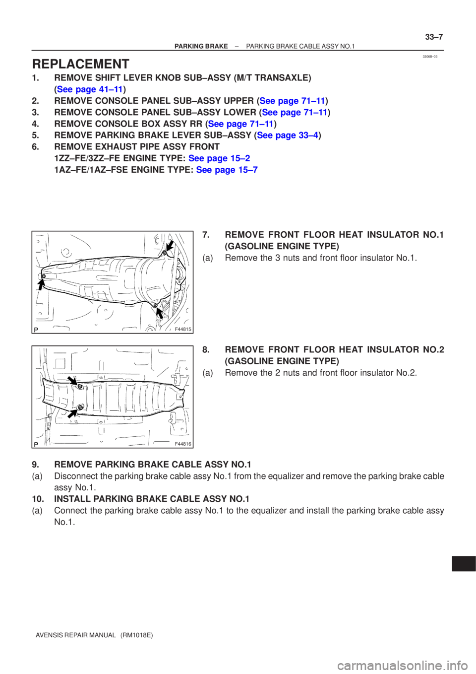
7. REMOVE FRONT FLOOR HEAT INSULATOR NO.1(GASOLINE ENGINE TYPE)
(a) Remove the 3 nuts and front floor insulator No.1.
8. REMOVE FRONT FLOOR HEAT INSULATOR NO.2 (GASOLINE ENGINE TYPE)
(a) Remove the 2 nuts and front floor insulator No.2.
9. REMOVE PARKING BRAKE CABLE ASSY NO.1
(a) Disconnect the parking brake cable assy No.1 from the equalizer and remove the parking brake cable assy No.1.
10. INSTALL PARKING BRAKE CABLE ASSY NO.1
(a) Connect the parking brake cable assy No.1 to the equalizer and install the park\
ing brake cable assy No.1.
Page 2665 of 5135
330C6±01
F44810
F41838
F44811
F44812
33±4
±
PARKING BRAKE PARKING BRAKE LEVER SUB±ASSY
AVENSIS REPAIR MANUAL (RM1018E)
REPLACEMENT
1. REMOVE FLOOR SHIFT SHIFT LEVER KNOB SUB±ASSY (M/T TRANSAXLE) (See page 41±11)
2.REMOVE CONSOLE PANEL SUB±ASSY UPPER (See page 71±11)
3.REMOVE CONSOLE PANEL SUB±ASSY LOWER (See page 71±11)
4.REMOVE CONSOLE BOX ASSY RR (See page 71±11)
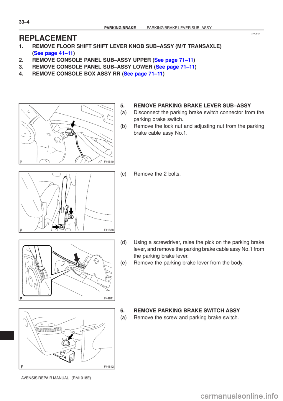
5. REMOVE PARKING BRAKE LEVER SUB±ASSY
(a) Disconnect the parking brake switch connector from theparking brake switch.
(b) Remove the lock nut and adjusting nut from the parking brake cable assy No.1.
(c) Remove the 2 bolts.
(d) Using a screwdriver, raise the pick on the parking brake lever, and remove the parking brake cable assy No.1 from
the parking brake lever.
(e) Remove the parking brake lever from the body.
6. REMOVE PARKING BRAKE SWITCH ASSY
(a) Remove the screw and parking brake switch.
Page 2668 of 5135
3300F±07
F44808
Lock NutAdjusting Nut
33±2
±
PARKING BRAKE PARKING BRAKE SYSTEM
AVENSIS REPAIR MANUAL (RM1018E)
ADJUSTMENT
1. REMOVE REAR WHEEL
2.ADJUST PARKING BRAKE SHOE CLEARANCE (See page 33±14)
3. INSTALL REAR WHEEL Torque: 103 N �m (1,050 kgf �cm, 76 ft �lbf)
4. INSPECT PARKING BRAKE LEVER TRAVEL
(a) Pull the parking brake lever all the way up, and count the number of cli\
cks. Parking brake lever travel: 6 ± 9 clicks at 196 N (20 kgf, 44.1 lbf)\
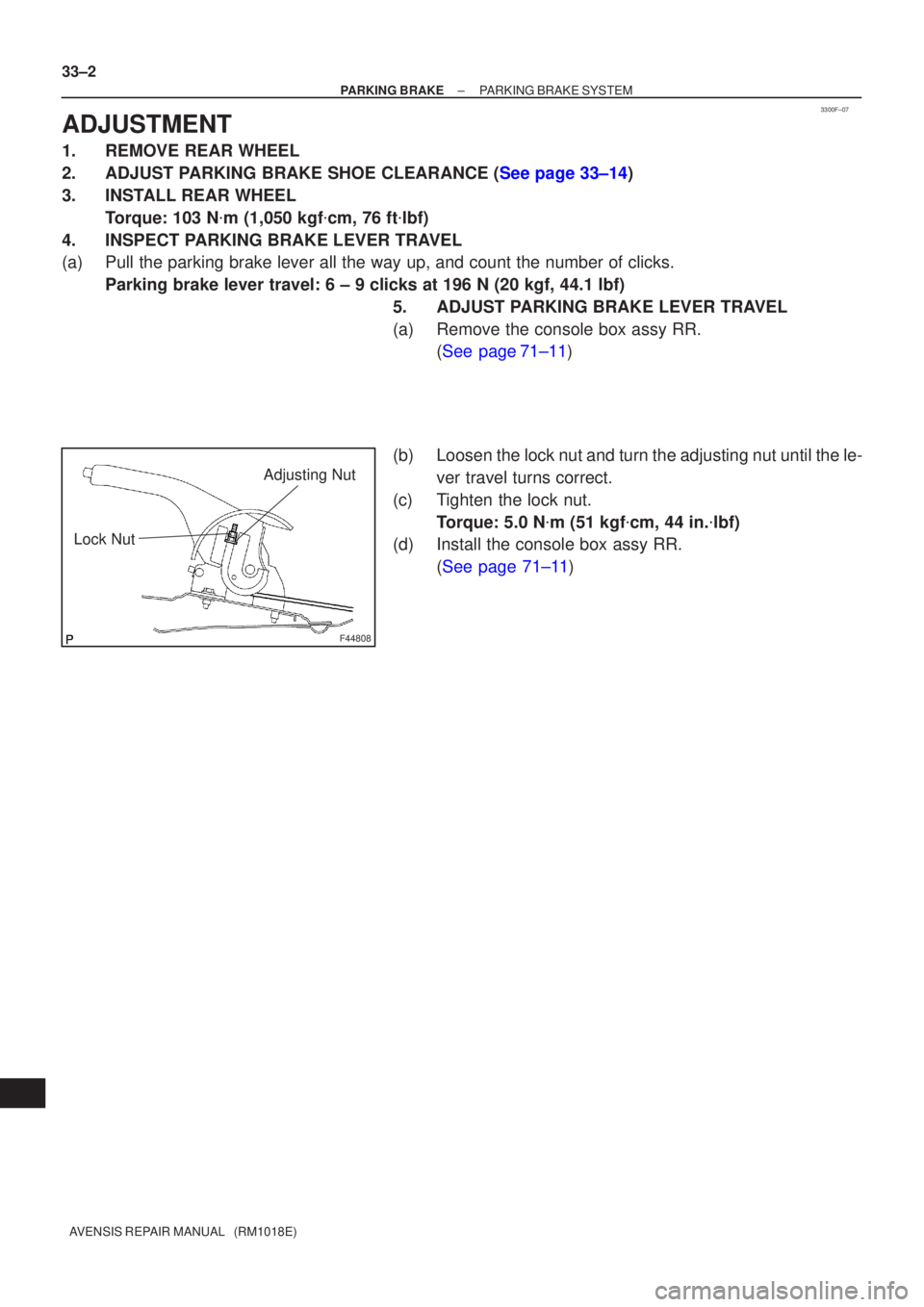
5. ADJUST PARKING BRAKE LEVER TRAVEL
(a) Remove the console box assy RR.(See page71±11)
(b) Loosen the lock nut and turn the adjusting nut until the le- ver travel turns correct.
(c) Tighten the lock nut. Torque: 5.0 N �m (51 kgf �cm, 44 in. �lbf)
(d) Install the console box assy RR.
(See page 71±11)
Page 2721 of 5135
410DR±01
D26893
D26895
D30474
D30474
±
MANUAL TRANSMISSION/TRANSAXLE FLOOR SHIFT SHIFT LEVER ASSY (MTM)
41±11
AVENSIS REPAIR MANUAL (RM1018E)
REPLACEMENT
1.REMOVE FLOOR SHIFT SHIFT LEVER KNOB SUB±ASSY (See page 71±11)
2.REMOVE CONSOLE PANEL UPPER (See page 71±11)
3.REMOVE CONSOLE PANEL SUB±ASSY LOWER (See page 71±11)
4.REMOVE CONSOLE BOX ASSY REAR (See page 71±11)
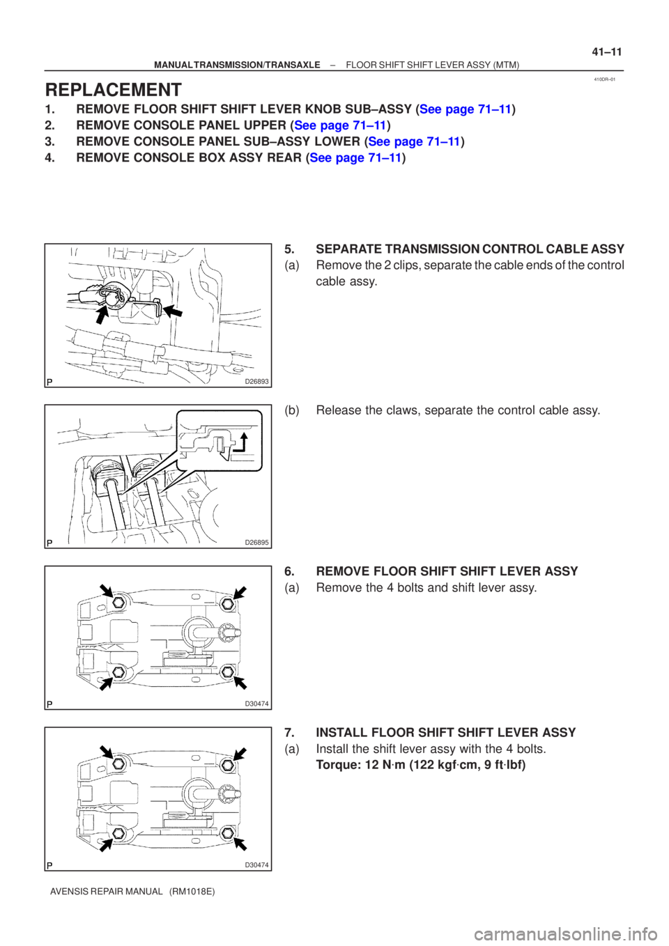
5. SEPARATE TRANSMISSION CONTROL CABLE ASSY
(a) Remove the 2 clips, separate the cable ends of the controlcable assy.
(b) Release the claws, separate the control cable assy.
6. REMOVE FLOOR SHIFT SHIFT LEVER ASSY
(a) Remove the 4 bolts and shift lever assy.
7. INSTALL FLOOR SHIFT SHIFT LEVER ASSY
(a) Install the shift lever assy with the 4 bolts. Torque: 12 N �m (122 kgf �cm, 9 ft �lbf)
Page 2733 of 5135
4011N±01
D28034
Claw
Shift Lock Release Link
D28033
Shift Lever Plate
C88567
40±74
±
AUTOMATIC TRANSMISSION / TRANS FLOOR SHIFT PARKING LOCK CABLE ASSY
AVENSIS REPAIR MANUAL (RM1018E)
FLOOR SHIFT PARKING LOCK CABLE ASSY
REPLACEMENT
1.PRECAUTION (See page 60±29)
2. DISCONNECT BATTERY NEGATIVE TERMINAL
3.REMOVE INSTRUMENT PANEL HOLE COVER (See page 71±11)
4.REMOVE INSTRUMENT PANEL AIR BAG ASSY (See page 60±29)
5.REMOVE INSTRUMENT PANEL UNDER COVER SUB±ASSY NO.1 (See page 71±11)
6.REMOVE STEERING COLUMN COVER LWR (See page 50±9)
7.REMOVE STEERING COLUMN COVER (See page 50±9)
8.REMOVE CONSOLE PANEL SUB±ASSY UPPER (See page 71±11)
9.REMOVE CONSOLE PANEL UPPER ASSY (See page 71±11)
10.REMOVE CONSOLE REAR END PANEL (See page 71±11)
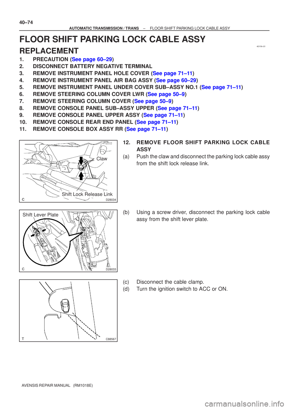
11.REMOVE CONSOLE BOX ASSY RR (See page 71±11) 12. REMOVE FLOOR SHIFT PARKING LOCK CABLEASSY
(a) Push the claw and disconnect the parking lock cable assy from the shift lock release link.
(b) Using a screw driver, disconnect the parking lock cable assy from the shift lever plate.
(c) Disconnect the cable clamp.
(d) Turn the ignition switch to ACC or ON.