Page 3969 of 5135
± DIAGNOSTICSABS WITH EBD & BA & TRC & VSC SYSTEM
05±835
AVENSIS REPAIR MANUAL (RM1018E)
ABS WARNING LIGHT CIRCUIT (DOES NOT LIGHT UP)
CIRCUIT DESCRIPTION
If the ECU detects trouble, it will prohibit ABS control, turn on the ABS warning light, and store the DTC.
Connect terminals Tc and CG of the DLC3 to make the ABS warning light blink and output the DTC.
0543F±04
Page 3971 of 5135
±
DIAGNOSTICS ABS WITH EBD & BA & TRC & VSC SYSTEM
05±837
AVENSIS REPAIR MANUAL (RM1018E)
INSPECTION PROCEDURE
HINT:
Start the inspection from step 1 if you are using the hand±held tester and\
start from step 2 if you are not using
the hand±held tester.
1PERFORM ACTIVE TEST BY HAND±HELD TESTER(ABS WARNING LIGHT)
(a)Check that ºONº and ºOFFº of the ABS warning light is shown on th\
e combination meter by the hand±
held tester.
OKREPLACE ABS & TRACTION ACTUATOR ASSY(See page 32±57)
NG
2 INSPECT ABS WARNING LIGHT
(a)See combination meter troubleshooting on page 71±1. NG REPAIR OR REPLACE COMBINATION METERASSEMBLY
OK
3 CHECK HARNESS AND CONNECTOR(SKID CONTORL ECU ± CMBINATION METER)
(a) Check for an open or short circuit in harness and connector between the skid \
control ECU and com-
bination meter (See page 01±32).
NG REPAIR OR REPLACE HARNESS ORCONNECTOR
OK
REPLACE ABS & TRACTION ACTUATOR ASSY(See page 32±57)
Page 3972 of 5135
05±844
± DIAGNOSTICSABS WITH EBD & BA & TRC & VSC SYSTEM
AVENSIS REPAIR MANUAL (RM1018E)
TRC OFF INDICATOR, TRC CUT SWITCH CIRCUIT
CIRCUIT DESCRIPTION
This is the TRC control main switch. When the TRC OFF switch is pressed, TRC control goes off and the
TRC OFF indicator illuminates. Also, turn the TRC OFF indicator light to ºONº when the VSC system is at
the fail safe control. If the ignition switch is turned off, TRC control surely comes on the next time the ignition
switch is turned ON.
0543I±04
Page 3974 of 5135

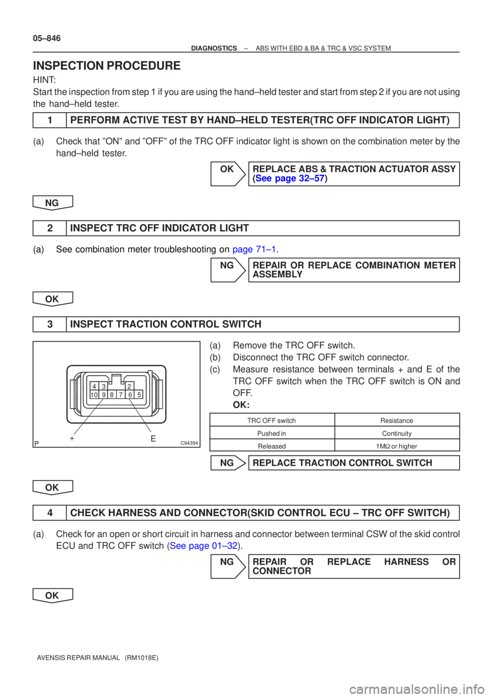
C94394
2
3
4
5
6
7
8
9
10
+
E
05±846
±
DIAGNOSTICS ABS WITH EBD & BA & TRC & VSC SYSTEM
AVENSIS REPAIR MANUAL (RM1018E)
INSPECTION PROCEDURE
HINT:
Start the inspection from step 1 if you are using the hand±held tester and\
start from step 2 if you are not using
the hand±held tester.
1PERFORM ACTIVE TEST BY HAND±HELD TESTER(TRC OFF INDICATOR LIGHT)
(a)Check that ºONº and ºOFFº of the TRC OFF indicator light is shown on the combinati\
on meter by the hand±held tester.
OKREPLACE ABS & TRACTION ACTUATOR ASSY(See page 32±57)
NG
2INSPECT TRC OFF INDICATOR LIGHT
(a)See combination meter troubleshooting on page 71±1. NGREPAIR OR REPLACE COMBINATION METERASSEMBLY
OK
3INSPECT TRACTION CONTROL SWITCH
(a)Remove the TRC OFF switch.
(b)Disconnect the TRC OFF switch connector.
(c)Measure resistance between terminals + and E of the TRC OFF switch when the TRC OFF switch is ON and
OFF.
OK:
TRC OFF switchResistance
Pushed inContinuity
Released1M� or higher
NGREPLACE TRACTION CONTROL SWITCH
OK
4CHECK HARNESS AND CONNECTOR(SKID CONTROL ECU ± TRC OFF SWITCH)
(a)Check for an open or short circuit in harness and connector between terminal \
CSW of the skid control ECU and TRC OFF switch (See page 01±32).
NG REPAIR OR REPLACE HARNESS ORCONNECTOR
OK
Page 3975 of 5135
±
DIAGNOSTICS ABS WITH EBD & BA & TRC & VSC SYSTEM
05±847
AVENSIS REPAIR MANUAL (RM1018E)
5CHECK HARNESS AND CONNECTOR(SKID CONTROL ECU ± COMBINATION
METER)
(a)Check for an open or short circuit in harness and connector between the skid \
control ECU and com-
bination meter (See page 01±32).
NG REPAIR OR REPLACE HARNESS ORCONNECTOR
OK
REPLACE ABS & TRACTION ACTUATOR ASSY(See page 32±57)
Page 3976 of 5135
F45144
Combination MeterSkid Control ECU
With Actuator
Engine Room J/B No.4 Engine Room R/B No.1 & Engine Room J/B No.1
Engine Room R/B No.3Driver Side J/BI13
Ignition SW
IG2 AM2
B±R B±RB±R B±W22
C1115
C11
SlipLG8
IE1LG4
S1
CACA
J8 J26 J8 J26
(*3) (*4)
(*3) (*4)B±W18
DA2
DH
1
1A 1
12AM2
1
4A1
4B
3 3 B±G (*1) B±G (*1)FL MAIN
B (*2) B (*2)Battery 1
IE4
(*3)1
IP1
(*4)64 IGN J/CIND
*1: 1AZ±FSE
*2: 1CD±FTV*3: LHD
*4: RHD 05±848
± DIAGNOSTICSABS WITH EBD & BA & TRC & VSC SYSTEM
AVENSIS REPAIR MANUAL (RM1018E)
SLIP INDICATOR LIGHT CIRCUIT
CIRCUIT DESCRIPTION
The SLIP indicator blinks during TRC & VSC operation.
WIRING DIAGRAM
0543J±04
Page 3977 of 5135
±
DIAGNOSTICS ABS WITH EBD & BA & TRC & VSC SYSTEM
05±849
AVENSIS REPAIR MANUAL (RM1018E)
INSPECTION PROCEDURE
HINT:
Start the inspection from step 1 if you are using the hand±held tester and\
start from step 2 if you are not using
the hand±held tester.
1PERFORM ACTIVE TEST BY HAND±HELD TESTER(SLIP INDICATOR LIGHT)
(a)Check that ºONº and ºOFFº of the SLIP indicator light is shown on\
the combination meter by the hand±
held tester.
OKREPLACE ABS & TRACTION ACTUATOR ASSY(See page 32±57)
NG
2 INSPECT SLIP INDICATOR LIGHT
(a)See combination meter troubleshooting on page 71±1. NG REPAIR OR REPLACE COMBINATION METERASSEMBLY
OK
3 CHECK HARNESS AND CONNECTOR(SKID CONTROL ECU ± COMBINATION METER)
(a) Check for an open or short circuit in harness and connector between terminal IND of the skid control
ECU and combination meter (See page 01±32).
NG REPAIR OR REPLACE HARNESS ORCONNECTOR
OK
REPLACE ABS & TRACTION ACTUATOR ASSY(See page 32±57)
Page 3978 of 5135
± DIAGNOSTICSABS WITH EBD & BA & TRC & VSC SYSTEM
05±831
AVENSIS REPAIR MANUAL (RM1018E)
DTC AlwaysON MALFUNCTION IN ECU(VSC WARNING
LIGHT)
CIRCUIT DESCRIPTION
When the ECU stores DTC, the VSC warning light illuminates on the combination meter.
DTC No.DTC Detecting ConditionTrouble Area
Always ONMalfunction in skid control ECU
�Battery
�IC regulator
�Power source circuit
�Skid control ECU
0543E±04