Page 226 of 5135
05±58
±
DIAGNOSTICS SFI SYSTEM(1ZZ±FE/3ZZ±FE)
AVENSIS REPAIR MANUAL (RM1018E)
5CHECK FUSE(EFI No.2) (See page 05±45)
NGCHECK FOR SHORT IN ALL HARNESS AND COMPONENTS CONNECTED FUSE
OK
6CHECK HARNESS AND CONNECTOR(HEATED OXYGEN SENSOR ± ECM) (See page 05±45)
NGREPAIR OR REPLACE HARNESS OR CONNECTOR
OK
7CHECK HARNESS AND CONNECTOR(EFI RELAY ± HEATED OXYGEN SENSOR) (See page 05±45)
NGREPAIR OR REPLACE HARNESS OR
CONNECTOR
OK
8CHECK AIR INDUCTION SYSTEM
(a)Check for vacuum leaks in air induction system. NGREPAIR OR REPLACE AIR INDUCTION SYSTEM
OK
9CHECK FUEL PRESSURE (See page 11±5)
(a) Check the fuel pressure (high or low pressure). NG REPAIR OR REPLACE FUEL SYSTEM
OK
10INSPECT FUEL INJECTOR ASSY(INJECTION AND VOLUME) (See page 11±8)
NG REPLACE FUEL INJECTOR ASSY
OK
REPLACE HEATED OXYGEN SENSOR
11 PERFORM CONFIRMATION DRIVING PATTERN
GO
Page 227 of 5135
± DIAGNOSTICSSFI SYSTEM (1ZZ±FE/3ZZ±FE)
05±59
AVENSIS REPAIR MANUAL (RM1018E)
12 READ OUTPUT DTC(HEATED OXYGEN SENSOR DTCS ARE OUTPUT AGAIN)
(a) Read the DTC using the hand±held tester.
Result:
Display (DTC output)Proceed to
ºP0130 and/or P0136º are not output againA
ºP0130 and/or P136º are output againB
B CHECK FOR INTERMITTENT PROBLEMS
A
REPLACE HEATED OXYGEN SENSOR
Page 228 of 5135

Platinum ElectrodeHeater
Exhaust Gas
CoverIdeal Air±Fuel Mixture
Output Voltage
Richer ± Air Fuel Ratio ± Leaner Element
AA
± DIAGNOSTICS")
A66651A±A SectionAir Solid Electrolyte
(Zirconia Element)
Platinum ElectrodeHeater
Exhaust Gas
CoverIdeal Air±Fuel Mixture
Output Voltage
Richer ± Air Fuel Ratio ± Leaner Element
AA
± DIAGNOSTICSSFI SYSTEM (1ZZ±FE/3ZZ±FE)
05±45
AVENSIS REPAIR MANUAL (RM1018E)
DTC P0125 INSUFFICIENT COOLANT TEMP. FOR
CLOSED LOOP FUEL CONTROL
CIRCUIT DESCRIPTION
The heated oxygen sensor is the planar type. Compared to the conventional type, the sensor element and
the heater portions have a narrower overall. The heater can directly conduct its heat to the zirconia element
via the alumina, it helps to accerate the sensor activation.
To obtain a high purification rate for the CO, HC and NOx components of the exhaust gas, a three ± way
catalytic converter is used. For the most efficient use of the three ± way catalytic converter, the air ± fuel ratio
must be precisely controlled so that it is always close to the stoichiometric air ± fuel ratio.
The heated oxygen sensor has the characteristic whereby its output voltage changes suddenly in the vicinity
of the stoichiometric air±fuel ratio. This is used to detect the oxygen concentration in the exhaust gas and
provide the ECM with feedback control the air±fuel ratio.
When the air±fuel ratio becomes LEAN, the oxygen concentration in the exhaust gas increases. And the
heated oxygen sensor informs the ECM of the LEAN condition (low voltage, i. e. less than 0.45 V ).
When the air±fuel ratio is RICHER than the stoichiometric air±fuel ratio, the oxygen concentration in the ex-
haust gas is reduced. And the heated oxygen sensor informs the ECM of the RICH condition (high voltage,
i. e. more than 0.45V). The ECM judges by the voltage output from the heated oxygen sensor whether the
air±fuel ratio is RICH or LEAN and controls the injection time accordingly. If the malfunction of the heated
oxygen sensor causes an output of abnomal voltage, the ECM becomes unable to perform accurate air±fuel
ratio control.
The heated oxygen sensors include a heater which heats the zirconia element. The heater is controlled by
the ECM. When the intake air volume is low (the temperature of the exhaust gas is low), current flows to the
heater in order to heat the sensor for the accurate oxygen concentration detection.
DTC NoDTC Detecting ConditionTrouble Area
P0125
After engine is warmed up, heated oxygen sensor output* does
not change when conditions (a), (b), (c) and (d) continue for at
least 1.5 min:
*: Output value changes at inside of the ECM only
(a) Engine speed: 1,400 rpm or more
(b) Vehicle speed: 40 to 100 km/h (25 to 62 mph)
(c) Throttle valve is not fully closed
(d) 180 sec. or more after starting engine�Open or short in heated oxygen sensor circuit
�Heated oxygen sensor
�Air induction system
�Fuel pressure
�Injector
�Gas leakage in exhaust system
� ECM
05C69±01
Page 229 of 5135
A79067
HT1A
4
E12
Y
OX1A
23
E12
HT1B
4
E10
OX1B
21
E12
B ECM
3 EH
H17
Heated
Oxygen
Sensor
(Bank 1
Sensor 2) H7
Heated
Oxygen
Sensor
(Bank 1
Sensor 1)
B±W
21
4 E2
+B HT
OX B
P
(*1) E2
28
*1: Shielded
BR
From
Terminal 3 of
EFI Relay
(See Page 05±124)
4 4
2 1 EFI
No.2
B±W
EA1
13
B±W
B±W
IK1
10
IH2
1
B±WBR BR BR
BR
IK2
IH2
18
3 E2
+B HT
OX BR
BR
(*1)(*1)
(*1)
(*1) (*1)
(*1) P
BB
J13 J12 E
D
J13
D
J13
E
J12D
J12
D
Junction
Connector IK2
7
IH2 4
IH2
2
Engine Room
R/B No.4
E13
B±W B±W 3
2 1
4
05±46
±
DIAGNOSTICS SFI SYSTEM (1ZZ±FE/3ZZ±FE)
AVENSIS REPAIR MANUAL (RM1018E)
HINT:
� ���� ���������� �
�\f���\b�� ��� ��� ��������� ������ �� ������� ������ ������� �� ��� ������ � !"
��� ������ ��� ºDIAGNOSIS / OBD/MOBD / DATA LIST / ALLº.
WIRING DIAGRAM
Page 230 of 5135

Injection volume
Output voltage
Output voltage of heated oxy")
+25 %
±12.5 %
More than 0.55 V
Less than 0.4V
Case 1
Case 2
Case 3
Case 4
Output voltage of heated oxygen
sensor (sensor 1: front sensor)
Injection volume
Output voltage
Output voltage of heated oxygen
sensor (sensor 2: rear sensor)Mainly suspect
trouble area
OK
+25 %
±12.5 %
More than 0.55 V
Less than 0.4V
Injection volume
Output voltage
+25 %
±12.5 %
More than 0.55 V
Less than 0.4V
Injection volume
Output voltage
Sensor 1: front sensor
(sensor 1, heater, sensor 1
circuit)
+25 %
±12.5 %
More than 0.55 V
Less than 0.4V
Injection volume
Output voltage
+25 %
±12.5 %
Injection volume
Output voltage
NG
+25 %
±12.5 %
Injection volume
Output voltage
NG
+25 %
±12.5 %
Injection volume
Output voltage
NG
+25 %
±12.5 %
Injection volume
Output voltage
NGExtremely rich or lean of the
actual air±fuel ratio
(Injector, fuel pressure, gas
leakage in exhaust system,
etc.) OK
OK
OK
No reaction
No reaction
No reaction No reaction
�
Sensor 2: rear sensor
(sensor 2, heater, sensor 2
circuit)
± DIAGNOSTICSSFI SYSTEM (1ZZ±FE/3ZZ±FE)
05±47
AVENSIS REPAIR MANUAL (RM1018E)
INSPECTION PROCEDURE
HINT:
Hand±held tester only:
Narrowing down the trouble area is possible by performing ACTIVE TEST of the following ºA/F CONTROLº
(heated oxygen sensor or other trouble areas can be distinguished).
(a) Perform ACTIVE TEST by the hand±held tester (A/F CONTROL).
HINT:
ºA/F CONTROLº is an ACTIVE TEST which changes the injection volume ±12.5 % or +25 %.
(1) Connect the hand±held tester to the DLC3 on the vehicle.
(2) Turn the ignition switch ON.
(3) Warm up the engine with the engine speed at 2,500 rpm for approximately 90 sec.
(4) Select the item ºDIAGNOSIS / OBD/MOBD / ACTIVE TEST / A/F CONTROLº.
(5) Perform ºA/F CONTROLº with the engine in an idle condition (press the right or left button).
Result:
Heated oxygen sensor reacts in accordance with increase and decrease of injection volume:
+25 % � rich output: More than 0.55 V
±12.5 % � lean output: Less than 0.4 V
NOTICE:
There is a few second delay in the sensor 1 (front sensor) output, and there is about 20 seconds delay
in the sensor 2 (rear sensor)output.
Page 231 of 5135

AVENSIS REPAIR MANUAL (RM1018E)
The following procedure of A/F CONTROL enable the technician to check and graph voltage output of the
heated oxygen")
05±48
±
DIAGNOSTICS SFI SYSTEM(1ZZ±FE/3ZZ±FE)
AVENSIS REPAIR MANUAL (RM1018E)
The following procedure of A/F CONTROL enable the technician to check and graph voltage output of the
heated oxygen sensor.
For displaying the graph indication, enter ºACTIVE TEST / A/F CONTROL / \
USER DATA,º then select ºO2S
B1S1 and O2S B1S2º by pressing ºYESº button and push ºENTERº \
button before pressing ºF4º button.
HINT:
�If different DTCs that are related to a different system are output simultaneously while terminal E2 is
used as a ground terminal, terminal E2 may be open.
�Read freeze frame data using \f���� ����\b�\f��\f�
� Freeze frame data records the engine conditions
when a malfunction is detected. When troubleshooting, it is useful for d\
etermining whether the vehicle
was running or stopped, the engine was warmed up or not, the air±fuel ra\
tio was lean or rich, etc. at
the time of the malfunction.
�A high heated oxygen sensor (sensor 1) voltage (0.55 V or more) coul\
d be caused by a rich air fuel
mixture. Check for conditions that would cause the engine to run rich.
�A low heated oxygen sensor (sensor 1) voltage (0.4 V or less) could b\
e caused by a lean air fuel mix-
ture. Check for conditions that would cause the engine to run lean.
1CHECK OTHER DTC OUTPUT(BESIDES DTC P0125)
(a)Read the DTC using the hand±held tester. Result:
Display (DTC output)Proceed to
Only ºP0125º is outputA
ºP0125º and other DTCs are outputB
HINT:
If any other codes besides ºP0125º are output, perform the troublesh\
oot on that DTC before.
BGO TO RELEVANT DTC CHART (See page 05±16)
A
2 READ VALUE OF HAND±HELD TESTER(OUTPUT VOLTAGE OF HEATED OXYGEN SENSOR)
(a) Warm up the engine to the normal operating temperature above 75 �C (169 �F).
(b) Read the output voltage of the heated oxygen sensor when the engine rpm \
is suddenly increased.
HINT:
Quickly accelerate the engine to 4,000 rpm 3 times using the accelerator\
pedal. Standard:
Heated oxygen sensor outputs a RICH signal (0.45 V or more) at least o\
nce.
OK Go to step 13
NG
Page 232 of 5135
A79112
+BE2
Heated Oxygen Sensor
H7 HT
OX
A73938
+B
E2
Heated Oxygen Sensor
H17 HT
OX
������
� �
A79069
Engine Room R/B No.4 EFI No.2 Fuse
±
DIAGNOSTICS SFI SYSTEM(1ZZ±FE/3ZZ±FE)
05±49
AVENSIS REPAIR MANUAL (RM1018E)
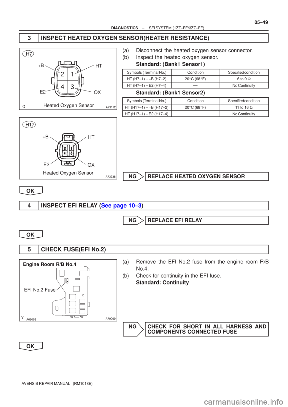
3INSPECT HEATED OXYGEN SENSOR(HEATER RESISTANCE)
(a)Disconnect the heated oxygen sensor connector.
(b)Inspect the heated oxygen sensor.
Standard: (Bank1 Sensor1)
Symbols (Terminal No.)ConditionSpecified condition
HT (H7±1) ± +B (H7±2)20�C (68 �F)6 to 9 �
HT (H7±1) ± E2 (H7±4)�No Continuity
Standard: (Bank1 Sensor2)
Symbols (Terminal No.)ConditionSpecified condition
HT (H17±1) ± +B (H17±2)20�C (68 �F)11 to 16 �
HT (H17±1) ± E2 (H17±4)�No Continuity
NGREPLACE HEATED OXYGEN SENSOR
OK
4INSPECT EFI RELAY (See page 10±3)
NG REPLACE EFI RELAY
OK
5 CHECK FUSE(EFI No.2)
(a) Remove the EFI No.2 fuse from the engine room R/B No.4.
(b) Check for continuity in the EFI fuse. Standard: Continuity
NG CHECK FOR SHORT IN ALL HARNESS AND COMPONENTS CONNECTED FUSE
OK
Page 233 of 5135

A79068
HT1AHT1B
E12E10
ECM Connector
OX1AOX1B
E13
E2
OX+B
E2 HT
Heated Oxygen Sensor Connector Wire Harness Side
H7
A79114
Heated Oxygen Sensor ConnectorA73939
OX+B
E2 HT
Wire Harness Side
H17
05±50
± DIAGNOSTICSSFI SYSTEM (1ZZ±FE/3ZZ±FE)
AVENSIS REPAIR MANUAL (RM1018E)
6 CHECK HARNESS AND CONNECTOR(HEATED OXYGEN SENSOR ± ECM)
(a) Disconnect the heated oxygen sensor connector.
(b) Disconnect the E10, E12 and E13 ECM connector.
(c) Check for continuity between the wire harness side con-
nectors.
Standard (Check for open): (Bank1 Sensor1)
Symbols (Terminal No.)Specified condition
HT (H7±1) ± HT1A (E12±4)
OX (H7±3) ± OX1A (E12±23)Continuity
E2 (H7±4) ± E2 (E13±28)
y
Standard (Check for short): (Bank1 Sensor1)
Symbols (Terminal No.)Specified condition
HT (H7±1) or HT1A (E12±4) ± Body groundNo continuityOX (H7±3) or OX1A (E12±23) ± Body groundNo continuity
Standard (Check for open): (Bank1 Sensor2)
Symbols (Terminal No.)Specified condition
HT (H17±1) ± HT1B (E10±4)
OX (H17±3) ± OX1B (E12±21)Continuity
E2 (H17±4) ± E2 (E13±28)
y
Standard (Check for short): (Bank1 Sensor2)
Symbols (Terminal No.)Specified condition
HT (H17±1) or HT1B (E10±4) ± Body groundNo continuityOX (H17±3) or OX1B (E12±21) ± Body groundNo continuity
NG REPAIR OR REPLACE HARNESS OR
CONNECTOR
OK

AVENSIS REPAIR MANUAL (RM1018E)
5CHECK FUSE(EFI No.2) (See page 05±45)
NGCHECK FOR SHORT IN ALL HARNESS AND COMPONENTS CONNECTED FUSE
OK
6CHECK HAR")

05±59
AVENSIS REPAIR MANUAL (RM1018E)
12 READ OUTPUT DTC(HEATED OXYGEN SENSOR DTCS ARE OUTPUT AGAIN)
(a) Read the DTC using the hand±held tester.
Result:")
 H7
Heated
Oxygen
Sensor
(Bank 1
Sensor 1)
B±W
21
4 E2
+B HT
OX B
P
(*1) E2
28
*1:")