Page 4869 of 5135

D26407
SST
Snap Ring
D03806D30852
Underdrive
Brake Return
Spring
D26406
Underdrive Brake Piston
D03794
O−ringO−ring
− AUTOMATIC TRANSMISSION / TRANSAUTOMATIC TRANSAXLE ASSY (U151E/U151F)
40−39
U151E, U151F A/T REPAIR MANUAL (RM1021U)
72. REMOVE BREATHER PLUG NO.2 (ATM)
73. REMOVE UNDERDRIVE BRAKE RETURN SPRING
SUB−ASSY
(a) Place SST on the return spring, and compress the return
spring with a press.
SST 09387−00020
(b) Using a snap ring expander, remove the snap ring.
NOTICE:
SStop the press when the spring sheet is lowered1−
2 mm (0.039−0.078 in.) from the snap ring groove, to
prevent the spring sheet from deforming.
SDo not expand the snap ring excessively.
74. INSPECT UNDERDRIVE BRAKE RETURN SPRING
SUB−ASSY
(a) Using a vernier calipers, measure the free length of the
spring together with the spring seat.
Standard free length:13.24 mm (0.5213 in.)
75. REMOVE UNDERDRIVE BRAKE PISTON
(a) Apply compressed air (392 kPa, 4.0 kgf/cm
2, 57 psi) to the
transaxle case to remove the underdrive brake piston.
(b) Remove the 2 O−rings from the underdrive brake piston.
Page 4870 of 5135
D03605
SSTHold
Turn
D03914
Underdrive
Clutch Drum
Oil Seal Ring
D26383
D03606
SST
Hold
Turn
D03915
Underdrive
Output
Shaft Oil
Seal Ring
40−40
− AUTOMATIC TRANSMISSION / TRANSAUTOMATIC TRANSAXLE ASSY (U151E/U151F)
U151E, U151F A/T REPAIR MANUAL (RM1021U)
76. REMOVE NEEDLE ROLLER BEARING
(a) Using SST, remove the needle−roller bearing from the
transaxle case.
SST 09387−00041 (09387−01010, 09387−01030,
09387−01040)
77. REMOVE UNDERDRIVE CLUTCH DRUM OIL SEAL
RING
(a) Remove the 2 oil seal rings from the transaxle case.
78. REMOVE TRANSAXLE CASE NO.1PLUG
(a) Remove the 2 transaxle case No. 1 plugs.
(b) Remove the 2 O−rings from the 2 transaxle case No. 1
plugs.
79. REMOVE UNDERDRIVE CYLINDRICAL ROLLER
BEARING
(a) Using SST, remove the underdrive cylindrical roller bear-
ing from the transaxle case.
SST 09514−35011
80. REMOVE UNDERDRIVE OUTPUT SHAFT OIL SEAL
RING
(a) Remove the oil seal ring from the transaxle housing.
Page 4871 of 5135
D26400
Differential
Gear Lube
Apply TubeTransaxle Apply
Tube Clamp
− AUTOMATIC TRANSMISSION / TRANSAUTOMATIC TRANSAXLE ASSY (U151E/U151F)
40−41
U151E, U151F A/T REPAIR MANUAL (RM1021U)
81. REMOVE DIFFERENTIAL GEAR LUBE APPLY TUBE
(a) Remove the bolt, transaxle apply tube clamp and differen-
tial gear lube apply tube from the transaxle housing.
Page 4872 of 5135
C89118
AB
CDE
F
HIJ
KG 40−42
− AUTOMATIC TRANSMISSION / TRANSAUTOMATIC TRANSAXLE ASSY (U151E/U151F)
U151E, U151F A/T REPAIR MANUAL (RM1021U)
82. BEARING POSITION
Page 4873 of 5135
− AUTOMATIC TRANSMISSION / TRANSAUTOMATIC TRANSAXLE ASSY (U151E/U151F)
40−43
U151E, U151F A/T REPAIR MANUAL (RM1021U)
MarkFront Race Diameter
Inside / Outside mm (in.)Thrust Bearing Diameter
Inside / Outside mm (in.)Rear Race Diameter
Inside / Outside mm (in.)
A−57.2 (2.252) / 84.96 (3.3449)56.4 (2.220) / 83.0 (3.268)
B−37.73 (1.4854) / 58.0 (2.283)−
C−33.85 (1.3327) / 52.2 (2.055)−
D24.94 (0.982)23.5 (0.925) / 44.0(1.732)−
E−36.3 (1.429) / 51.93 (2.044)34.5 (1.358) / 48.35 (1.904)
F34.35 (1.352) / 56.57 (2.227)32.45 (1.278) / 56.48 (2.223)−
G40.15 (1.581) / 59.25 (2.333)38.65 (1.522) / 59.79 (2.354)38.65 (1.522) / 59.25 (2.332)
H−53.6 (2.110) / 69.6 (2.740)−
I33.02 (1.3) / 45.8 (1.803)31.85 (1.254) / 57.3 (2.256)−
J−24.79 (0.976) / 39.5 (1.555)23.6 (0.929) / 37.95 (1.494)
K−56.3 (2.216) / 75.96 (2.991)−
Page 4874 of 5135

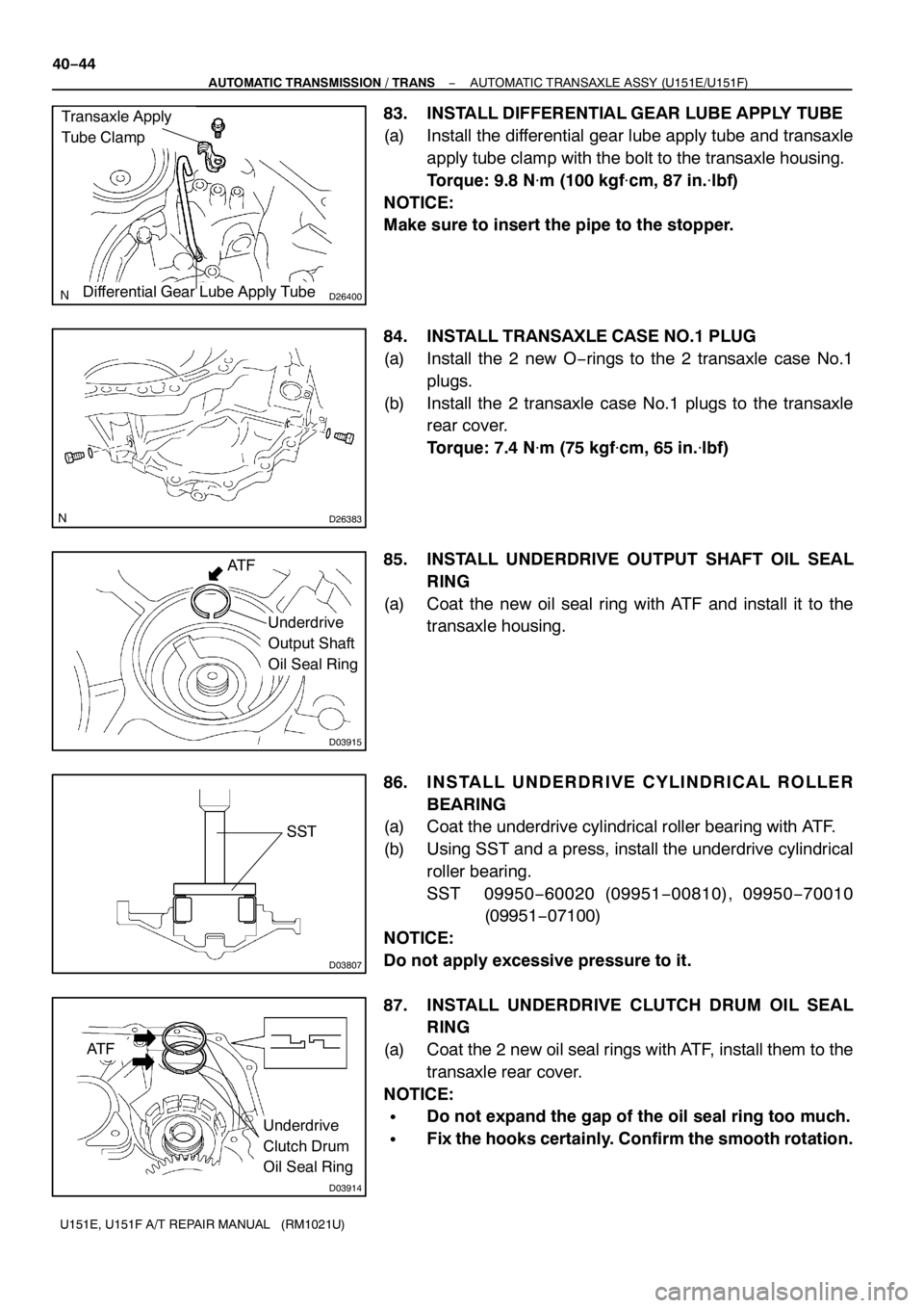
D26400
Transaxle Apply
Tube Clamp
Differential Gear Lube Apply Tube
D26383
Underdrive
Output Shaft
Oil Seal Ring
D03915
AT F
D03807
SST
D03914
Underdrive
Clutch Drum
Oil Seal Ring
AT F 40−44
− AUTOMATIC TRANSMISSION / TRANSAUTOMATIC TRANSAXLE ASSY (U151E/U151F)
U151E, U151F A/T REPAIR MANUAL (RM1021U)
83. INSTALL DIFFERENTIAL GEAR LUBE APPLY TUBE
(a) Install the differential gear lube apply tube and transaxle
apply tube clamp with the bolt to the transaxle housing.
Torque: 9.8 N�m(100 kgf�cm, 87 in.�lbf)
NOTICE:
Make sure to insert the pipe to the stopper.
84. INSTALL TRANSAXLE CASE NO.1PLUG
(a) Install the 2 new O−rings to the 2 transaxle case No.1
plugs.
(b) Install the 2 transaxle case No.1 plugs to the transaxle
rear cover.
Torque: 7.4 N�m (75 kgf�cm, 65 in.�lbf)
85. INSTALL UNDERDRIVE OUTPUT SHAFT OIL SEAL
RING
(a) Coat the new oil seal ring with ATF and install it to the
transaxle housing.
86. INSTALL UNDERDRIVE CYLINDRICAL ROLLER
BEARING
(a) Coat the underdrive cylindrical roller bearing with ATF.
(b) Using SST and a press, install the underdrive cylindrical
roller bearing.
SST 09950−60020 (09951−00810), 09950−70010
(09951−07100)
NOTICE:
Do not apply excessive pressure to it.
87. INSTALL UNDERDRIVE CLUTCH DRUM OIL SEAL
RING
(a) Coat the 2 new oil seal rings with ATF, install them to the
transaxle rear cover.
NOTICE:
SDo not expand the gap of the oil seal ring too much.
SFix the hooks certainly. Confirm the smooth rotation.
Page 4875 of 5135

D03809
Vinyl Tape
SST
D03810
SST
D03794
O−ringO−ring
D26764
Underdrive
Brake Piston
− AUTOMATIC TRANSMISSION / TRANSAUTOMATIC TRANSAXLE ASSY (U151E/U151F)
40−45
U151E, U151F A/T REPAIR MANUAL (RM1021U)
88. INSTALL NEEDLE ROLLER BEARING
(a) Wind a vinyl tape around SST at the place 4.0 mm (0.157
in.) above from the bottom end until the thickness of the
wound tape is about 5.0 mm (0.197 in.).
NOTICE:
Clean SST to remove deposited oil, before winding a vinyl
tape.
(b) Coat the needle roller bearing with ATF.
(c) Using SST and a press, install the needle−roller bearing
to the transaxle case.
SST 09950−60010 (09951−00320), 09950−70010
(09951−07100)
NOTICE:
When the wound vinyl tape contacts the transaxle case,
stop press−fitting.
89. INSTALL UNDERDRIVE BRAKE PISTON
(a) Coat the 2 new O−rings with ATF, install them to the un-
derdrive brake piston.
NOTICE:
SAssemble the O−ring carefully not to have a twist and
a pinching.
SApply enough ATF to the O−ring prior to assembling.
(b) Coat the underdrive brake piston with ATF.
(c) Install the underdrive brake piston to the transaxle case.
NOTICE:
Be careful not to damage the O−ring.
Page 4876 of 5135

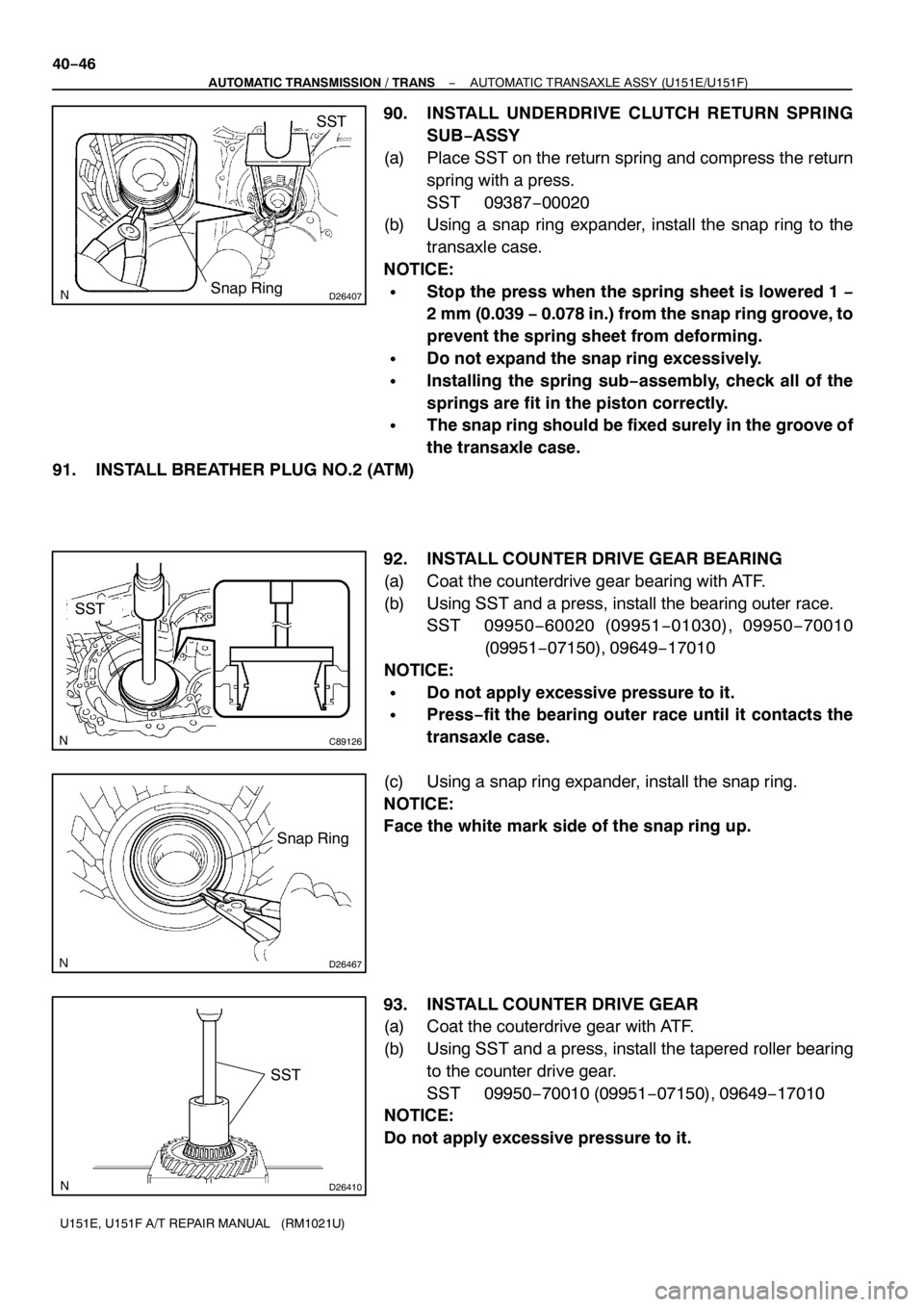
D26407
SST
Snap Ring
C89126
SST
D26467
Snap Ring
D26410
SST
40−46
− AUTOMATIC TRANSMISSION / TRANSAUTOMATIC TRANSAXLE ASSY (U151E/U151F)
U151E, U151F A/T REPAIR MANUAL (RM1021U)
90. INSTALL UNDERDRIVE CLUTCH RETURN SPRING
SUB−ASSY
(a) Place SST on the return spring and compress the return
spring with a press.
SST 09387−00020
(b) Using a snap ring expander, install the snap ring to the
transaxle case.
NOTICE:
SStop the press when the spring sheet is lowered1−
2 mm (0.039−0.078 in.) from the snap ring groove, to
prevent the spring sheet from deforming.
SDo not expand the snap ring excessively.
SInstalling the spring sub−assembly, check all of the
springs are fit in the piston correctly.
SThe snap ring should be fixed surely in the groove of
the transaxle case.
91. INSTALL BREATHER PLUG NO.2 (ATM)
92. INSTALL COUNTER DRIVE GEAR BEARING
(a) Coat the counterdrive gear bearing with ATF.
(b) Using SST and a press, install the bearing outer race.
SST 09950−60020 (09951−01030), 09950−70010
(09951−07150), 09649−17010
NOTICE:
SDo not apply excessive pressure to it.
SPress−fit the bearing outer race until it contacts the
transaxle case.
(c) Using a snap ring expander, install the snap ring.
NOTICE:
Face the white mark side of the snap ring up.
93. INSTALL COUNTER DRIVE GEAR
(a) Coat the couterdrive gear with ATF.
(b) Using SST and a press, install the tapered roller bearing
to the counter drive gear.
SST 09950−70010 (09951−07150), 09649−17010
NOTICE:
Do not apply excessive pressure to it.