Page 698 of 5135
A80462
SP1E2ECM Connector
E13
E10
A62954
Turn Wheel
4.5
to 5.5V
0V
05±642
±
DIAGNOSTICS ECD SYSTEM(1CD±FTV)
AVENSIS REPAIR MANUAL (RM1018E)
2INSPECT ECM(SP1 VOLTAGE)
(a)Shift the transmission to the neutral position.
(b)Jack up the vehicle.
(c)Turn the ignition switch ON.
(d)Measure the voltage between the specified terminals of the E10 and E13 ECM connectors as the wheel is turned
slowly.
Standard:
Symbols (Terminal No.)Specified condition
SP1 (E10±17) ± E2 (E13±28)Generated intermittently
HINT:
The output voltage should fluctuate ups and downs similarly to
the diagram on the left when the wheel is turned slowly.
NGREPAIR OR REPLACE HARNESS OR CONNECTOR
OK
REPLACE ECM (See page 10±65)
Page 699 of 5135
A81482
Reduction GearIntake Shutter Control Motor
Intake Shutter Valve
Intake Shutter Valve
Fully Opened Switch Intake Shutter Internal Structure
ON
OFF
CLOSE
OPEN
± DIAGNOSTICSECD SYSTEM (1CD±FTV)
05±633
AVENSIS REPAIR MANUAL (RM1018E)
DTC P0488 EXHAUST GAS RECIRCULATION
THROTTLE POSITION CONTROL
RANGE/PERFORMANCE
CIRCUIT DESCRIPTION
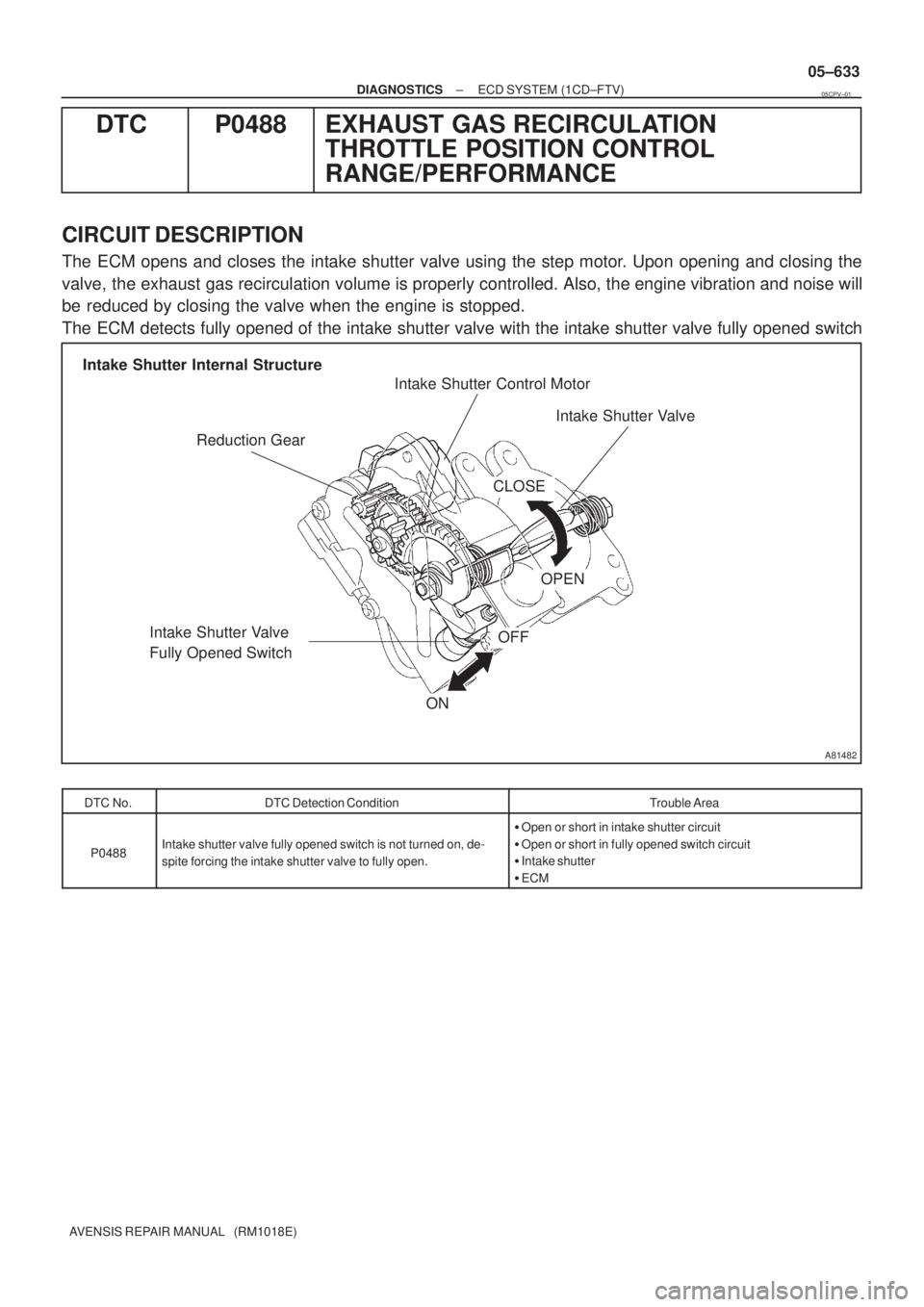
The ECM opens and closes the intake shutter valve using the step motor. Upon opening and closing the
valve, the exhaust gas recirculation volume is properly controlled. Also, the engine vibration and noise will
be reduced by closing the valve when the engine is stopped.
The ECM detects fully opened of the intake shutter valve with the intake shutter valve fully opened switch
DTC No.DTC Detection ConditionTrouble Area
P0488Intake shutter valve fully opened switch is not turned on, de-
spite forcing the intake shutter valve to fully open.
�Open or short in intake shutter circuit
�Open or short in fully opened switch circuit
�Intake shutter
�ECM
05CPV±01
Page 700 of 5135
A81510
Malfunction Detection
Actual Intake Shutter
Valve Opening Angle
ON
OFF Normal Abnormal
Fully Opened
Switch StatusOPEN CLOSE
Intake Shutter
Valve Control Motor
Step Counter
TimeAbnormal
Normal
OPEN CLOSE ECM Commanding Fully Open
05±634
± DIAGNOSTICSECD SYSTEM (1CD±FTV)
AVENSIS REPAIR MANUAL (RM1018E)
MONITOR DESCRIPTION
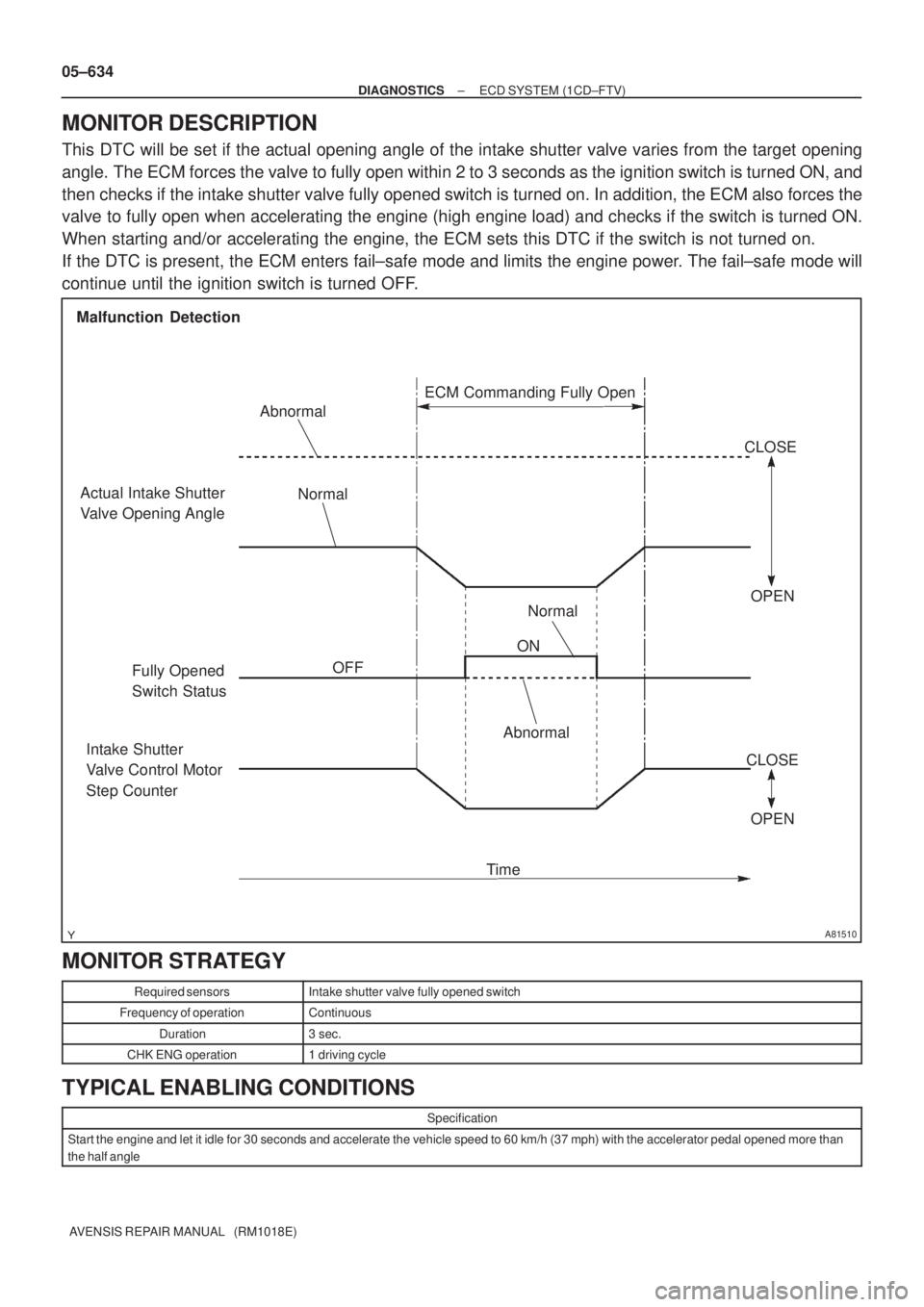
This DTC will be set if the actual opening angle of the intake shutter valve varies from the target opening
angle. The ECM forces the valve to fully open within 2 to 3 seconds as the ignition switch is turned ON, and
then checks if the intake shutter valve fully opened switch is turned on. In addition, the ECM also forces the
valve to fully open when accelerating the engine (high engine load) and checks if the switch is turned ON.
When starting and/or accelerating the engine, the ECM sets this DTC if the switch is not turned on.
If the DTC is present, the ECM enters fail±safe mode and limits the engine power. The fail±safe mode will
continue until the ignition switch is turned OFF.
MONITOR STRATEGY
Required sensorsIntake shutter valve fully opened switch
Frequency of operationContinuous
Duration3 sec.
CHK ENG operation1 driving cycle
TYPICAL ENABLING CONDITIONS
Specification
Start the engine and let it idle for 30 seconds and accelerate the vehicle speed to 60 km/h (37 mph) with the accelerator pedal opened more than
the half angle
Page 701 of 5135
A81906
ECM
D1
Intake Shutter
B
LU+A 15
E13
G
Y
LE13
E13
E1314
13
12LU±A
LU+B
LU±B 6
4
3
1From EFI MAIN Relay
5
2B±W
B±W
B±W
P±L
E1311
THOP 1
2 W±B
EIT3
Intake Shutter
Fully Opened Switch
± DIAGNOSTICSECD SYSTEM (1CD±FTV)
05±635
AVENSIS REPAIR MANUAL (RM1018E)
TYPICAL MALFUNCTION THRESHOLDS
Threshold
Intake shutter valve fully opened switch is not turned ON, despite the ECM commanding the intake shutter valve to open fully
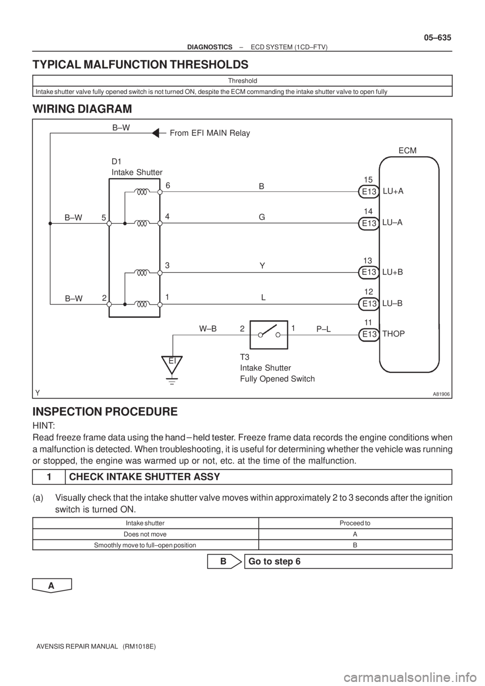
WIRING DIAGRAM
INSPECTION PROCEDURE
HINT:
Read freeze frame data using ��� �� ������ �����
� Freeze frame data records the engine conditions when
a malfunction is detected. When troubleshooting, it is useful for determining whether the vehicle was running
or stopped, the engine was warmed up or not, etc. at the time of the malfunction.
1 CHECK INTAKE SHUTTER ASSY
(a) Visually check that the intake shutter valve moves within approximately 2 to 3 seconds after the ignition
switch is turned ON.
Intake shutterProceed to
Does not moveA
Smoothly move to full±open positionB
B Go to step 6
A
Page 702 of 5135
A31135Intake Shutter Assy
05±636
±
DIAGNOSTICS ECD SYSTEM(1CD±FTV)
AVENSIS REPAIR MANUAL (RM1018E)
2CHECK INTAKE SHUTTER ASSY
(a)Check if the intake shutter valve moves as the lever is rotated by hand.
Intake shutterProceed to
Smoothly movedA
Difficult to move smoothlyB
BREPLACE INTAKE SHUTTER ASSY
(See page 10±61)
A
3INSPECT INTAKE SHUTTER ASSY
(a)Check the intake shutter for resistance. (1)Measure the resistance between the terminals.
RHD Resistance:
TerminalsTemperatureResistance
1 ± 2
1 ± 3at20�C(68�F)18to22 �4 ± 5at 20�C (68 �F)18 to 22 �
4 ± 6
LHD Resistance:
TerminalsTemperatureResistance
1 ± 3
2 ± 3at20�C(68�F)18to22�4 ± 6at 20�C (68 �F)18 to 22 �
5 ± 6
NGREPLACE INTAKE SHUTTER ASSY
(See page 10±61)
OK
Page 703 of 5135
A66060
E13
ECM Connector
LU+A LU±A LU±B
E1
LU+B
E12
A56892
Signal Waveform
20 V/
Division
10 msec./Division
LU+A
LU+B
LU±BLU±A
A80456
E13
ECM Connector
LU+A
LU±A LU±B
LU+B
A56871
D1
Wire Harness Side
Intake shutter Connector
±
DIAGNOSTICS ECD SYSTEM(1CD±FTV)
05±637
AVENSIS REPAIR MANUAL (RM1018E)
4INSPECT ECM(LU VOLTAGE)
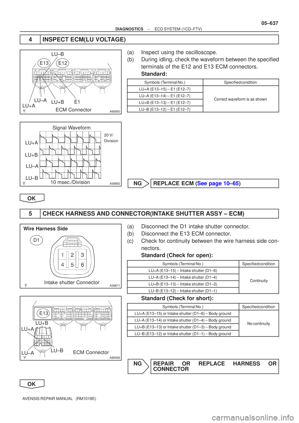
(a)Inspect using the oscilloscope.
(b)During idling, check the waveform between the specified
terminals of the E12 and E13 ECM connectors.
Standard:
Symbols (Terminal No.)Specified condition
LU+A (E13±15) ± E1 (E12±7)
LU±A (E13±14) ± E1 (E12±7)CorrectwaveformisasshownLU+B (E13±13) ± E1 (E12±7)Correct waveform is as shown
LU±B (E13±12) ± E1 (E12±7)
NGREPLACE ECM (See page 10±65)
OK
5 CHECK HARNESS AND CONNECTOR(INTAKE SHUTTER ASSY ± ECM)
(a) Disconnect the D1 intake shutter connector.
(b) Disconnect the E13 ECM connector.
(c) Check for continuity between the wire harness side con- nectors.
Standard (Check for open):
Symbols (Terminal No.)Specified condition
LU+A (E13±15) ± Intake shutter (D1±6)
LU±A (E13±14) ± Intake shutter (D1±4)ContinuityLU+B (E13±13) ± Intake shutter (D1±3)Continuity
LU±B (E13±12) ± Intake shutter (D1±1)
Standard (Check for short):
Symbols (Terminal No.)Specified condition
LU+A (E13±15) or Intake shutter (D1±6) ± Body ground
LU±A (E13±14) or Intake shutter (D1±4) ± Body groundNo continuityLU+B (E13±13) or Intake shutter (D1±3) ± Body groundNo continuity
LU±B (E13±12) or Intake shutter (D1±1) ± Body ground
NG REPAIR OR REPLACE HARNESS OR CONNECTOR
OK
Page 704 of 5135
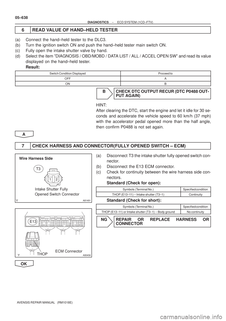
A81491
T3
Wire Harness Side
Intake Shutter Fully
Opened Switch Connector
A80456
E13
ECM ConnectorTHOP
05±638
± DIAGNOSTICSECD SYSTEM (1CD±FTV)
AVENSIS REPAIR MANUAL (RM1018E)
6 READ VALUE OF HAND±HELD TESTER
(a) Connect the hand±held tester to the DLC3.
(b) Turn the ignition switch ON and push the hand±held tester main switch ON.
(c) Fully open the intake shutter valve by hand.
(d) Select the item ºDIAGNOSIS / OBD/MOBD / DATA LIST / ALL / ACCEL OPEN SWº and read its value
displayed on the hand±held tester.
Result:
Switch Condition DisplayedProceed to
OFFA
ONB
B CHECK DTC OUTPUT RECUR (DTC P0488 OUT-
PUT AGAIN)
HINT:
After clearing the DTC, start the engine and let it idle for 30 se-
conds and accelerate the vehicle speed to 60 km/h (37 mph)
with the accelerator pedal opened more than the half angle,
then confirm P0488 is not set again.
A
7 CHECK HARNESS AND CONNECTOR(FULLY OPENED SWITCH ± ECM)
(a) Disconnect T3 the intake shutter fully opened switch con-
nector.
(b) Disconnect the E13 ECM connector.
(c) Check for continuity between the wire harness side con-
nectors.
Standard (Check for open):
Symbols (Terminal No.)Specified condition
THOP (E13±11) ± Intake shutter (T3±1)Continuity
Standard (Check for short):
Symbols (Terminal No.)Specified condition
THOP (E13±11) or Intake shutter (T3±1) ± Body groundNo continuity
NG REPAIR OR REPLACE HARNESS OR
CONNECTOR
OK
Page 705 of 5135
± DIAGNOSTICSECD SYSTEM (1CD±FTV)
05±639
AVENSIS REPAIR MANUAL (RM1018E)
CHECK DTC OUTPUT RECUR (DTC P0488 OUTPUT AGAIN)
HINT:
After clearing the DTC, start the engine and let it idle for 30 seconds and accelerate the vehicle speed to
60 km/h (37 mph) with the accelerator pedal opened more than the half angle, then confirm P0488 is not
set again.