Page 4557 of 5135

1302Z−04
A77123
SST
A60595E2 VC
13−6− INTAKETURBO CHARGER SYSTEM (1CD−FTV)(From
September, 2003)
AVENSIS Supplement (RM1045E)
ON−VEHICLE INSPECTION
1. INSPECT INTAKE AIR SYSTEM
(a) Check for leakage or clogging between the air cleaner housing and turbocharger inlet and between
the turbocharger outlet and cylinder head.
ConditionOperation
Clogged air cleanerClean or replace the element
Collapsed or deformed hosesRepair or replace
Leakage from connectionsCheck each connection and repair
Cracks in componentsCheck and replace
2. INSPECT EXHAUST SYSTEM
(a) Check for leakage or clogging between the cylinder head and turbocharger inlet and between the
turbocharger outlet and exhaust pipe.
ConditionOperation
Deformed componentsRepair or replace
Foreign material in passagesRemove
Leakage from componentsRepair or replace
Cracks in componentsCheck and replace
3. CHECK TURBOCHARGING PRESSURE
(a) Warm up the engine.
(b) Using a 3−way connector, connect SST (turbocharger
pressure gauge) to the hose leading to the intake air con-
nector.
SST 09992−00242
(c) While depressing the clutch pedal, press the accelerator
pedal down fully. Measure the turbocharging pressure at
the maximum speed (5,100 to 5,250 rpm).
Standard pressure:
15 to 45 kPa (0.15 to 0.46 kgf/cm
2, 2.2 to 6.5 psi)
If the pressure is less than specification, check both the intake
air and exhaust systems for leakage.
If there is no leakage, check if the actuator hose has discon-
nected. If not, check the turbocharger.
If the pressure is greater than the specification, check if the ac-
tuator hose has disconnected or cracked. If not, check the
turbocharger.
4. INSPECT TURBO PRESSURE SENSOR
(a) Inspect the power source voltage.
(1) Disconnect the turbo pressure sensor connector.
(2) Turn the ignition switch to ON.
(3) Using a voltmeter, measure the voltage between
connector terminals 3 (VC) and 1 (E2) of the wire
harness side.
Voltage: 4.5 to 5.5 V
If the result is not as specified, check the wiring and ECM.
Page 4558 of 5135

A87890
PIM (+)
E2 (−) ECM Connector
Vacuum SST
E13 E12
A77125
SST
Pressure
− INTAKETURBO CHARGER SYSTEM (1CD−FTV)(From
September, 2003)13−7
AVENSIS Supplement (RM1045E)
(4) Turn the ignition switch to OFF.
(5) Reconnect the turbo pressure sensor connector.
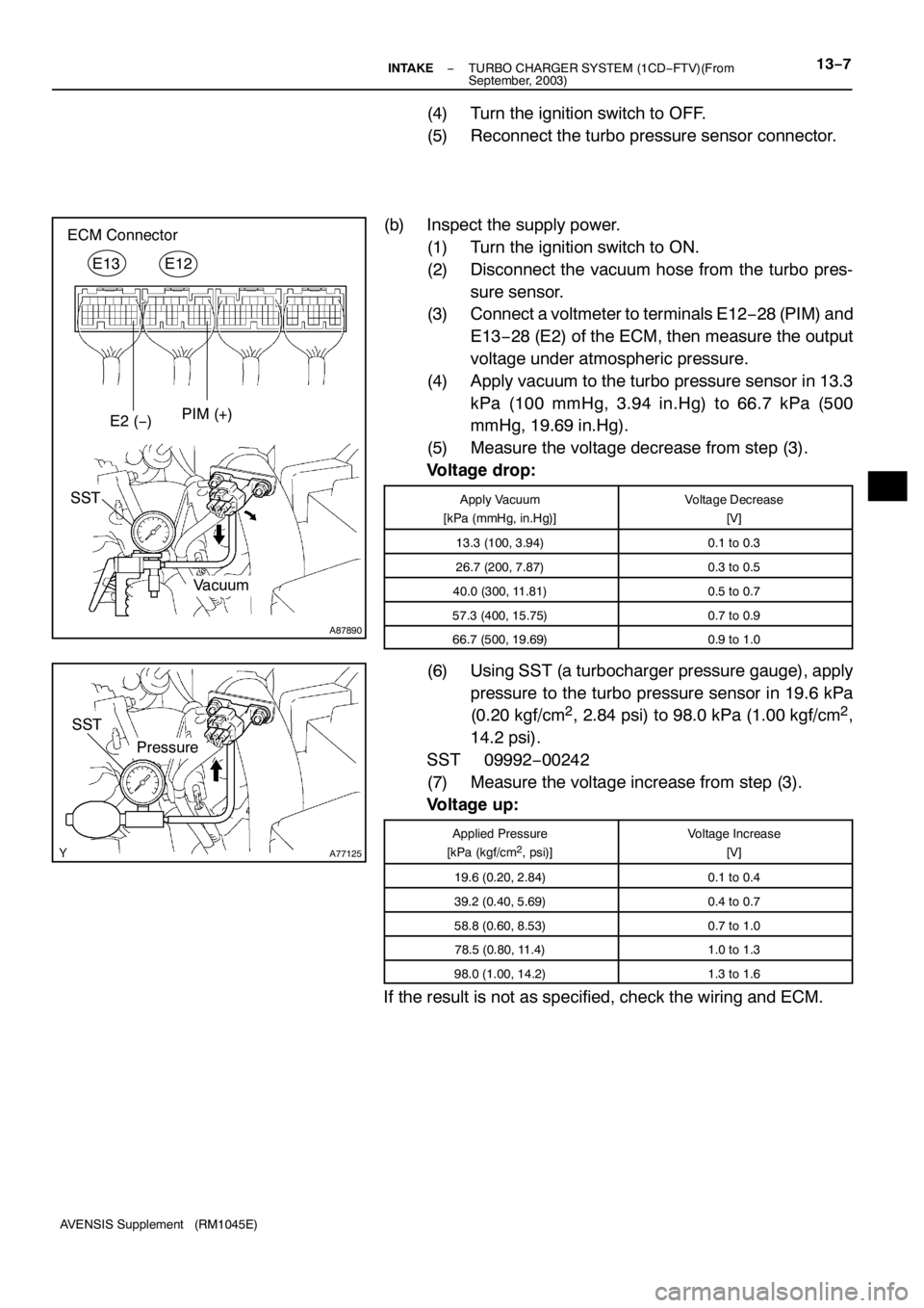
(b) Inspect the supply power.
(1) Turn the ignition switch to ON.
(2) Disconnect the vacuum hose from the turbo pres-
sure sensor.
(3) Connect a voltmeter to terminals E12−28 (PIM) and
E13−28 (E2) of the ECM, then measure the output
voltage under atmospheric pressure.
(4) Apply vacuum to the turbo pressure sensor in 13.3
kPa (100 mmHg, 3.94 in.Hg) to 66.7 kPa (500
mmHg, 19.69 in.Hg).
(5) Measure the voltage decrease from step (3).
Voltage drop:
Apply Vacuum
[kPa (mmHg, in.Hg)]Voltage Decrease
[V]
13.3 (100, 3.94)0.1 to 0.3
26.7 (200, 7.87)0.3 to 0.5
40.0 (300, 11.81)0.5 to 0.7
57.3 (400, 15.75)0.7 to 0.9
66.7 (500, 19.69)0.9 to 1.0
(6) Using SST (a turbocharger pressure gauge), apply
pressure to the turbo pressure sensor in 19.6 kPa
(0.20 kgf/cm
2, 2.84 psi) to 98.0 kPa (1.00 kgf/cm2,
14.2 psi).
SST 09992−00242
(7) Measure the voltage increase from step (3).
Voltage up:
Applied Pressure
[kPa (kgf/cm2, psi)]
Voltage Increase
[V]
19.6 (0.20, 2.84)0.1 to 0.4
39.2 (0.40, 5.69)0.4 to 0.7
58.8 (0.60, 8.53)0.7 to 1.0
78.5 (0.80, 11.4)1.0 to 1.3
98.0 (1.00, 14.2)1.3 to 1.6
If the result is not as specified, check the wiring and ECM.
Page 4588 of 5135
A84696zNon−reusable part
N·m (kgf·cm, ft·lbf) : Specified torqueThrottle Body AssyThrottle Control Motor
Connector
zThrottle Body Gasket
Water By−pass Hose
No. 2
Water By−pass Hose
No. 1
9.0 (90, 80 in.�lbf)
x4
x4
21 (210, 15)Throttle Body Bracket
8.4 (86, 74 in.�lbf)
Ground TerminalWiring Harness
Protector
8.4 (86, 74 in.�lbf)
11−22
− FUELFUEL PUMP ASSY (2AZ−FSE)
AVENSIS Supplement (RM1045E)
Page 4590 of 5135

1111 4−01
A88253
(a)
(b)
Pull Out
A88252
(a)
(b)
(c)
(d)
A77920
RHD:
LHD:
−
FUEL FUEL INJECTOR ASSY (2AZ −FSE)
11 −13
AVENSIS Supplement (RM1045E)
REPLACEMENT
1. DISCHARGE FUEL SYSTEM PRESSURE (See page 11 −1)
2. REMOVE RADIATOR SUPPORT OPENING COVER (See page 10 −8)
3. REMOVE ENGINE ROOM COVER SIDE (See page 10 −8)
4. DISCONNECT ENGINE WIRE NO.3 (BATTERY NEGATIVE TERMINAL)
5. DRAIN ENGINE COOLANT (See page 16 −7)
6. REMOVE ENGINE COVER SUB −ASSY NO.1 (See page 10 −8)
7. REMOVE AIR CLEANER CAP SUB −ASSY (See page 10 −8)
8. REMOVE THROTTLE BODY ASSY (See page 10 −8)
9. REMOVE FUEL TUBE SUB −ASSY (See page 11 −24)
SST 09617 −24011
10. REMOVE FUEL HOSE (See page 11 −24)
11. REMOVE FUEL PIPE SUB −ASSY NO.1 (See page 11 −24)
SST 09023 −12900
12. REMOVE FUEL PUMP ASSY (See page 11 −24)
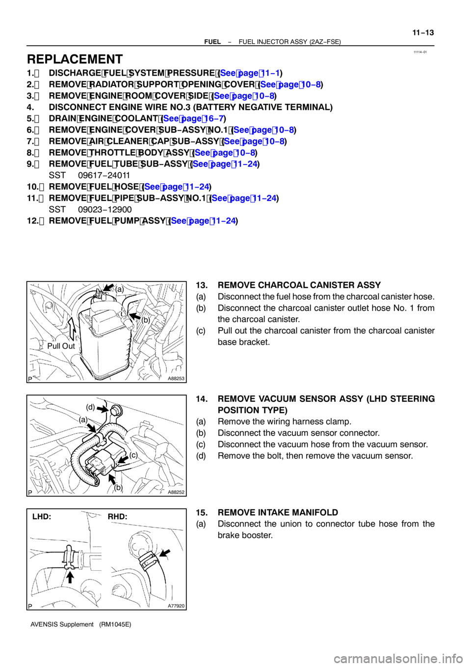
13. REMOVE CHARCOAL CANISTER ASSY
(a) Disconnect the fuel hose from the charcoal canister hose.
(b) Disconnect the charcoal canister outlet hose No. 1 from the charcoal canister.
(c) Pull out the charcoal canister from the charcoal canister base bracket.
14. REMOVE VACUUM SENSOR ASSY (LHD STEERING POSITION TYPE)
(a) Remove the wiring harness clamp.
(b) Disconnect the vacuum sensor connector.
(c) Disconnect the vacuum hose from the vacuum sensor.
(d) Remove the bolt, then remove the vacuum sensor.
15. REMOVE INTAKE MANIFOLD
(a) Disconnect the union to connector tube hose from the
brake booster.
Page 4592 of 5135
A88259
(g)(h)
(g)
A88260
Intake Manifold Intake Manifold
Insulator No. 1
A88261
(d)
(b)
(c)
(a)(b)(b)(b)
A88262
− FUELFUEL INJECTOR ASSY (2AZ−FSE)
11−15
AVENSIS Supplement (RM1045E)
(g) Disconnect the 2 vacuum hoses from the intake air control
valve and pressure sensor.
(h) Disconnect the pressure sensor connector.
(i) Remove the intake air control valve and gasket from the
cylinder head.
(j) Remove the intake manifold insulator No. 1 from the in-
take manifold.
(k) Remove the intake manifold from the vehicle.
16. REMOVE SURGE TANK STAY NO.1
(a) Disconnect the fuel pressure sensor connector.
(b) Disconnect the 4 fuel injector connectors.
(c) Remove the nut.
(d) Remove the wiring harness clamp, then remove the en-
gine wire.
(e) Remove the 2 bolts, then remove the surge tank stay No.
1.
Page 4601 of 5135

A88284Battery
A13269B12608
A91714
Hand−held Tester
11 −6
−
FUEL FUEL SYSTEM (2AZ −FSE)
AVENSIS Supplement (RM1045E)
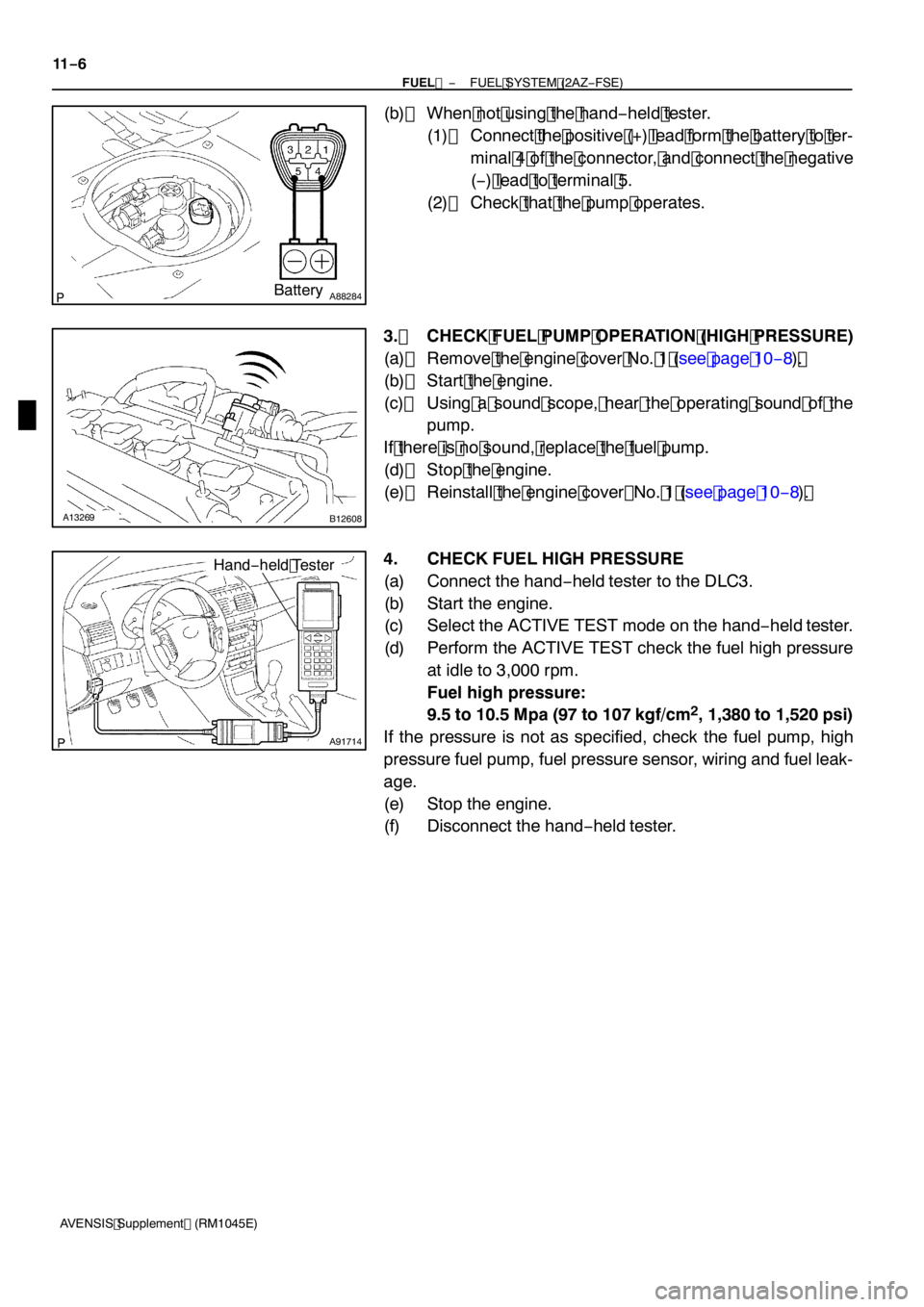
(b) When not using the hand −held tester.
(1) Connect the positive (+) lead form the battery to ter- minal 4 of the connector, and connect the negative
(− ) lead to terminal 5.
(2) Check that the pump operates.
3. CHECK FUEL PUMP OPERATION (HIGH PRESSURE)
(a) Remove the engine cover No. 1 (see page 10 −8) .
(b) Start the engine.
(c) Using a sound scope, hear the operating sound of the pump.
If there is no sound, replace the fuel pump.
(d) Stop the engine.
(e) Reinstall the engine cover No. 1 (see page 10 −8) .
4. CHECK FUEL HIGH PRESSURE
(a) Connect the hand −held tester to the DLC3.
(b) Start the engine.
(c) Select the ACTIVE TEST mode on the hand −held tester.
(d) Perform the ACTIVE TEST check the fuel high pressure at idle to 3,000 rpm.
Fuel high pressure:
9.5 to 10.5 Mpa (97 to 107 kgf/cm
2, 1,380 to 1,520 psi)
If the pressure is not as specified, check the fuel pump, high
pressure fuel pump, fuel pressure sensor, wiring and fuel leak-
age.
(e) Stop the engine.
(f) Disconnect the hand −held tester.
Page 4609 of 5135

100M2−01
A75903
Air
A66060
VG
EVGE12 ECM Connector
−
ENGINE CONTROL SYSTEM ECD SYSTEM (1CD−FTV)(From September, 2003)
10 −19
AVENSIS Supplement (RM1045E)
ECD SYSTEM (1CD −FTV)(From September, 2003)
ON −VEHICLE INSPECTION
1. INSPECT MASS AIR FLOW METER
(a) If you have the hand −held tester:
Check the operation.
(1) Connect the hand −held tester to the DLC3.
(2) Turn the ignition switch to ON.
(3) Select the item ”DIAGNOSIS / OBD / MOBD / DATA
LIST” on the hand −held tester.
(4) Blow air into the mass air flow (MAF) meter, then
check that the MAF reading in DATA LIST fluctu-
ates.
If the operation is not as specified, check the MAF meter
(see page 10 −22), wiring and ECM.
(b) If you have no hand −held tester:
Check the operation.
(1) Turn the ignition switch to ON.
(2) Connect the positive tester probe of a voltmeter to
terminal VG of the ECM, and the negative tester
probe of the voltmeter to terminal EVG of the ECM.
(3) Blow air into the MAF meter, then check that the voltage fluctuates.
If the operation is not as specified, check the MAF meter
(see page 10 −22), wiring and ECM.
2. INSPECT INTAKE SHUTTER
(a) Listen to the operating sounds of the throttle control mo- tor.
(1) Turn the ignition switch to ON.
(2) Listen to the operating sounds while turning the ac-
celerator pedal position sensor lever.
If a collision sound is heard, check the throttle control motor.
If no sound is heard, check the wire harness and ECM.
(b) If you have the hand −held tester:
Inspect the throttle position sensor.
(1) Connect the hand −held tester to the DLC3.
(2) Turn the ignition switch to ON.
(3) Select the item ”DIAGNOSIS / OBD / MOBD / DATE LIST” on the hand held −tester.
Page 4610 of 5135

A66060
E12
ECM Connector
E1
LUSL
A92422
Signal Waveform
10 msec./Dvision
10
−20
−
ENGINE CONTROL SYSTEM ECD SYSTEM (1CD−FTV)(From September, 2003)
AVENSIS Supplement (RM1045E)
(4) When turning the accelerator pedal position sensor lever t o t he f ull − open posit ion, check t hat t he
t hr ot t le v alve opening per cent age ( THRO TTLE
POS) of DATA LIST shows the standard value.
Standard throttle valve opening percentage:
60 % or higher
If the operation is not as specified, check the accelerator pedal
position sensor (see page 10 −22), wiring and ECM.
(c) If you have no hand −held tester:
(1) Inspect the throttle position sensor using a oscillo- scope.
(2) During idling, check the waveform between the spe- cified terminals of the E12 ECM connectors.
Standard:
Tester ConnectionSpecified Condition
LUSL (E12 −4) − E1 (E12 −7)Correct waveform is as shown on the left
If the operation is not as specified, check the accelerator pedal
position sensor (see page 10 −22), wiring and ECM.
(d) Inspect the air assist system.
(1) Start the engine, then check that the check engine warning light does not light up.
(2) Allow the engine to warm up to the normal operating
temperature.
(3) Turn the A/C compressor ON to OFF, then check the
idle speed (see page 14 −87).
Idle speed (transmission in neutral): 800 �á50 rpm
If the result is not as specified, check the wiring and ECM.
NOTICE:
Perform the inspection under condition without electrical
load.
(e) After taking the above steps (b) to (c), perform the driving test.
(f) Check that there is no sense of incongruity.