Page 3768 of 5135
C69553
C69552
C69551
C69633
SST
C69634
41±58
± MANUAL TRANSMISSION/TRANSAXLEINPUT SHAFT ASSY (E355/E356)
E355,E356 M/T REPAIR MANUAL (RM867E)
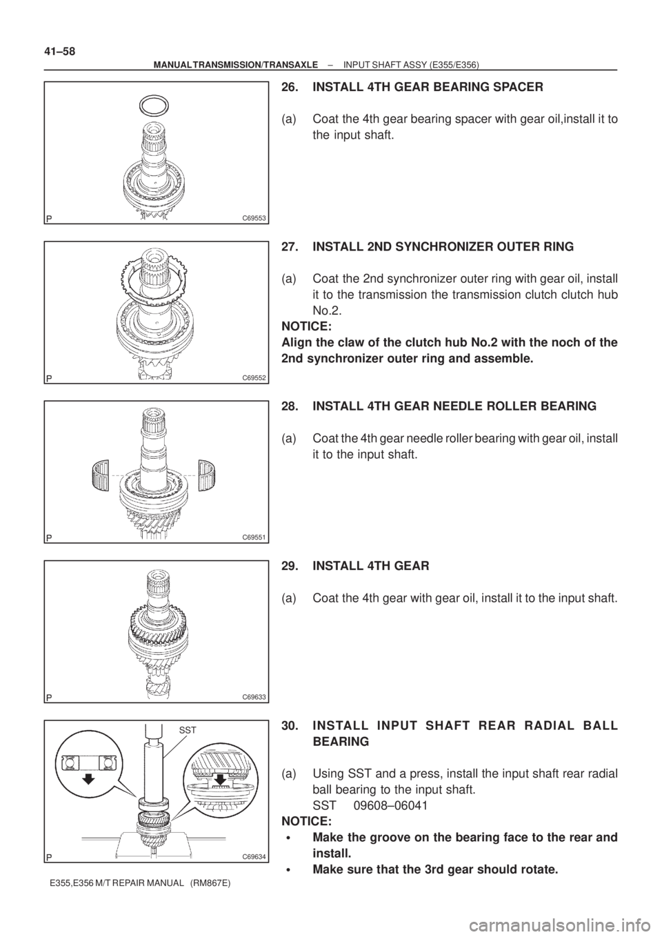
26. INSTALL 4TH GEAR BEARING SPACER
(a) Coat the 4th gear bearing spacer with gear oil,install it to
the input shaft.
27. INSTALL 2ND SYNCHRONIZER OUTER RING
(a) Coat the 2nd synchronizer outer ring with gear oil, install
it to the transmission the transmission clutch clutch hub
No.2.
NOTICE:
Align the claw of the clutch hub No.2 with the noch of the
2nd synchronizer outer ring and assemble.
28. INSTALL 4TH GEAR NEEDLE ROLLER BEARING
(a) Coat the 4th gear needle roller bearing with gear oil, install
it to the input shaft.
29. INSTALL 4TH GEAR
(a) Coat the 4th gear with gear oil, install it to the input shaft.
30. INSTALL INPUT SHAFT REAR RADIAL BALL
BEARING
(a) Using SST and a press, install the input shaft rear radial
ball bearing to the input shaft.
SST 09608±06041
NOTICE:
�Make the groove on the bearing face to the rear and
install.
�Make sure that the 3rd gear should rotate.
Page 3769 of 5135
C69635
C69549
± MANUAL TRANSMISSION/TRANSAXLEINPUT SHAFT ASSY (E355/E356)
41±59
E355,E356 M/T REPAIR MANUAL (RM867E)
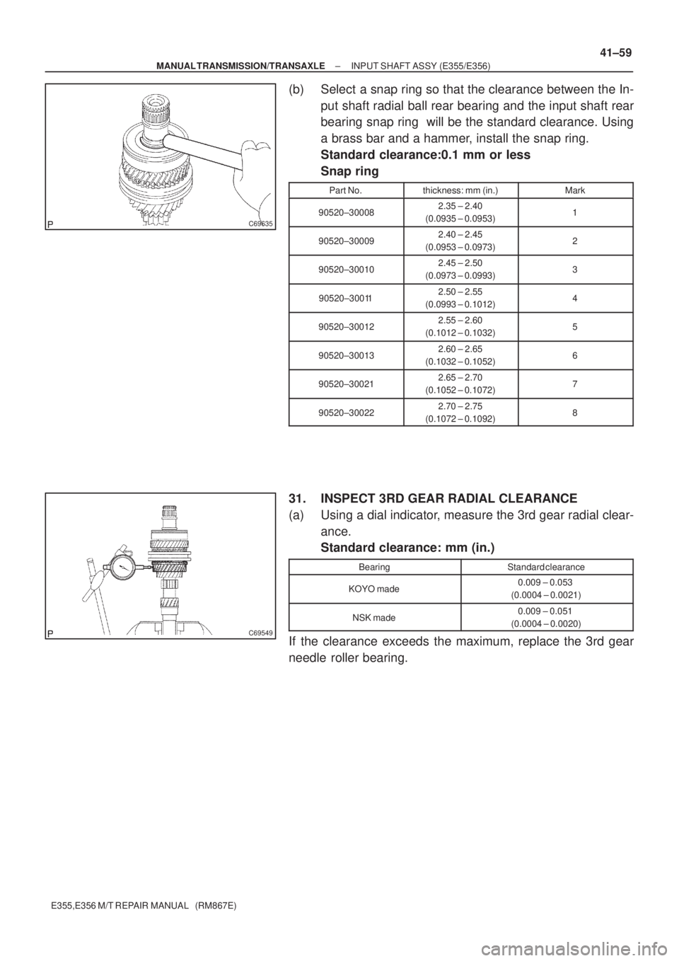
(b) Select a snap ring so that the clearance between the In-
put shaft radial ball rear bearing and the input shaft rear
bearing snap ring will be the standard clearance. Using
a brass bar and a hammer, install the snap ring.
Standard clearance:0.1 mm or less
Snap ring
Part No.thickness: mm (in.)Mark
90520±300082.35 ± 2.40
(0.0935 ± 0.0953)1
90520±300092.40 ± 2.45
(0.0953 ± 0.0973)2
90520±300102.45 ± 2.50
(0.0973 ± 0.0993)3
90520±300112.50 ± 2.55
(0.0993 ± 0.1012)4
90520±300122.55 ± 2.60
(0.1012 ± 0.1032)5
90520±300132.60 ± 2.65
(0.1032 ± 0.1052)6
90520±300212.65 ± 2.70
(0.1052 ± 0.1072)7
90520±300222.70 ± 2.75
(0.1072 ± 0.1092)8
31. INSPECT 3RD GEAR RADIAL CLEARANCE
(a) Using a dial indicator, measure the 3rd gear radial clear-
ance.
Standard clearance: mm (in.)
BearingStandard clearance
KOYO made0.009 ± 0.053
(0.0004 ± 0.0021)
NSK made0.009 ± 0.051
(0.0004 ± 0.0020)
If the clearance exceeds the maximum, replace the 3rd gear
needle roller bearing.
Page 3770 of 5135
C69548
C69547
C69546
41±60
± MANUAL TRANSMISSION/TRANSAXLEINPUT SHAFT ASSY (E355/E356)
E355,E356 M/T REPAIR MANUAL (RM867E)
32. INSPECT 4TH GEAR RADIAL CLEARANCE
(a) Using a dial indicator, measure the 4th gear radial clear-
ance.
Standard clearance: mm (in.)
BearingStandard clearance
KOYO made0.009 ± 0.053
(0.0004 ± 0.0021)
NSK made0.009 ± 0.051
(0.0004 ± 0.0020)
If the clearance exceeds the maximum, replace the 4th gear
needle roller bearing.
33. INSPECT 3RD GEAR THRUST CLEARANCE
(a) Using a dial indicator, measure the 3rd gear thrust clear-
ance.
Standard clearance:
0.1 ± 0.35 mm (0.0039 ± 0.0139 in.)
34. INSPECT 4TH GEAR THRUST CLEARANCE
(a) Using a feeler gauge, measure the 4th gear thrust clear-
ance.
Standard clearance:
0.1 ± 0.57 mm (0.0039 ± 0.0226 in.)
Page 3804 of 5135
0214S±01
02±2
± PREPARATIONENGINE MECHANICAL
1CD±FTV ENGINE REPAIR MANUAL (RM927E)
ENGINE MECHANICAL
PREPARATION
SST
09032±00100Oil Pan Seal CutterPARTIAL ENGINE ASSY(1CD±FTV)
09201±10000Valve Guide Bushing Remover &
Replacer SetCYLINDER HEAD ASSY(1CD±FTV)
(09201±01060)Valve Guide Bushing Remover &
Replacer 6CYLINDER HEAD ASSY(1CD±FTV)
09202±70020Valve Spring CompressorCYLINDER HEAD ASSY(1CD±FTV)
(09202±00010)AttachmentCYLINDER HEAD ASSY(1CD±FTV)
09223±15030Oil Seal & Bearing ReplacerPARTIAL ENGINE ASSY(1CD±FTV)
09223±46011Crankshaft Front Oil Seal
ReplacerPARTIAL ENGINE ASSY(1CD±FTV)
09248±55050Valve Clearance Adjust Tool SetPARTIAL ENGINE ASSY(1CD±FTV)
(09248±05510)Valve Lifter PressPARTIAL ENGINE ASSY(1CD±FTV)
(09248±05520)Valve Lifter StopperPARTIAL ENGINE ASSY(1CD±FTV)
09316±60011Transmission & Transfer Bearing
ReplacerPARTIAL ENGINE ASSY(1CD±FTV)
(09316±00011)Replacer PipePARTIAL ENGINE ASSY(1CD±FTV)
Page 3868 of 5135
3 2 1 45678
9 1 0 111 21 31 41 51 6
DLC3
A04550
FI0534
05±8
± DIAGNOSTICSSFI SYSTEM (1ZZ±FE/3ZZ±FE)
AVENSIS REPAIR MANUAL (RM1018E)
�Freeze frame data:
Freeze frame data records the engine conditions
(fuel system, calculator load, water temperature,
fuel trim, engine speed, vehicle speed, etc.) when
a malfunction is detected. When troubleshooting,
it is useful for determining whether the vehicle was
running or stopped, the engine was warmed up or
not, the air±fuel ratio was lean or rich, etc. at the
time of the malfunction.
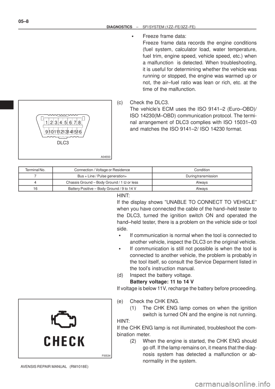
(c) Check the DLC3.
The vehicle's ECM uses the ISO 9141±2 (Euro±OBD)/
ISO 14230(M±OBD) communication protocol. The termi-
nal arrangement of DLC3 complies with ISO 15031±03
and matches the ISO 9141±2/ ISO 14230 format.
Terminal No.Connection / Voltage or ResidenceCondition
7Bus + Line / Pulse generation+During transmission
4Chassis Ground ± Body Ground / 1 � or lessAlways
16Battery Positive ± Body Ground / 9 to 14 VAlways
HINT:
If the display shows ºUNABLE TO CONNECT TO VEHICLEº
when you have connected the cable of the hand±held tester to
the DLC3, turned the ignition switch ON and operated the
hand±held tester, there is a problem on the vehicle side or tool
side.
�If communication is normal when the tool is connected to
another vehicle, inspect the DLC3 on the original vehicle.
�If communication is still not possible is when the tool is
connected to another vehicle, the problem is probably in
the tool itself, so consult the Service Deparment listed in
the tool's instruction manual.
(d) Inspect the battery voltage.
Battery voltage: 11 to 14 V
If voltage is below 11V, recharge the battery before proceeding.
(e) Check the CHK ENG.
(1) The CHK ENG lamp comes on when the ignition
switch is turned ON and the engine is not running.
HINT:
If the CHK ENG lamp is not illuminated, troubleshoot the com-
bination meter.
(2) When the engine is started, the CHK ENG should
go off. If the lamp remains on, it means that the diag-
nosis system has detected a malfunction or ab-
normality in the system.
Page 3869 of 5135
A76859
Hand±Held Tester
±
DIAGNOSTICS SFI SYSTEM (1ZZ±FE/3ZZ±FE)
05±9
AVENSIS REPAIR MANUAL (RM1018E)
2. DTC CHECK (Nomal Mode) :
NOTICE:
Hand±held tester only:
When the diagnosis system is switched from the normal
mode to the check (test) mode, it erases all DTCs and freeze
frame data recorded in the normal mode. So before switch-
ing modes, always check the DTCs and freeze frame data,
and then write them down.
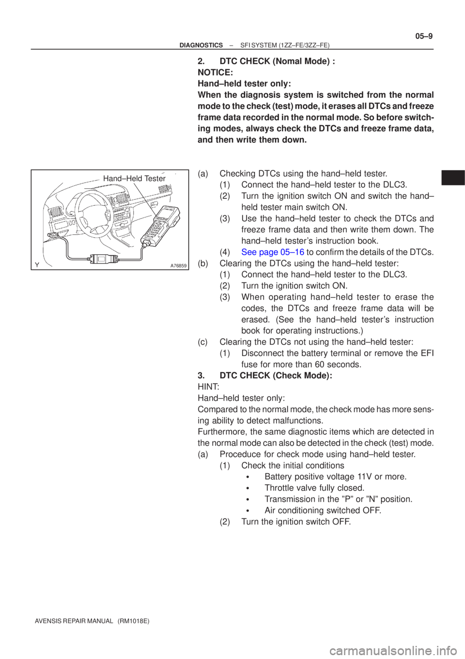
(a) Checking DTCs using the hand±held tester.
(1) Connect the hand±held tester to the DLC3.
(2) Turn the ignition switch ON and switch the hand±
held tester main switch ON.
(3) Use the hand±held tester to check the DTCs and freeze frame data and then write them down. The
hand±held tester's instruction book.
(4)See page 05±16 to confirm the details of the DTCs.
(b) Clearing the DTCs using the hand±held tester: (1) Connect the hand±held tester to the DLC3.
(2) Turn the ignition switch ON.
(3) When operating hand±held tester to erase the
codes, the DTCs and freeze frame data will be
erased. (See the hand±held tester's instruction
book for operating instructions.)
(c) Clearing the DTCs not using the hand±held tester: (1) Disconnect the battery terminal or remove the EFIfuse for more than 60 seconds.
3. DTC CHECK (Check Mode):
HINT:
Hand±held tester only:
Compared to the normal mode, the check mode has more sens-
ing ability to detect malfunctions.
Furthermore, the same diagnostic items which are detected in
the normal mode can also be detected in the check (test) mode.
(a) Proceduce for check mode using hand±held tester.
(1) Check the initial conditions
�Battery positive voltage 11V or more.
�Throttle valve fully closed.
�Transmission in the ºPº or ºNº position.
�Air conditioning switched OFF.
(2) Turn the ignition switch OFF.
Page 3887 of 5135
FI0534
A76859
Hand±Held Tester
05±152
±
DIAGNOSTICS SFI SYSTEM(1AZ±FE)
AVENSIS REPAIR MANUAL (RM1018E) Terminal No.
Connection / Voltage or ResidenceCondition
7Bus + Line / Pulse generation+During transmission
4Chassis Ground ± Body Ground / 1
� or lessAlways
16Battery Positive± Body Ground / 9 to 14 VAlways
HINT:
If the display shows ºUNABLE TO CONNECT TO VEHICLEº
when you have connected the cable of the hand±held tester to
the DLC3, turned the ignition switch ON and operated the
hand±held tester, there is a problem on the vehicle side or tool
side.
�If communication is normal when the tool is connected to
another vehicle, inspect the DLC3 on the original vehicle.
�If communication is still impossible when the tool is con-
nected to another vehicle, the problem is probably in the
tool itself, so consult the Service Deparment listed in the
tool's instruction manual.
(d)Inspect the battery voltage.
Battery voltage: 11 to 14 V
If voltage is below 11V, recharge the battery before proceeding.
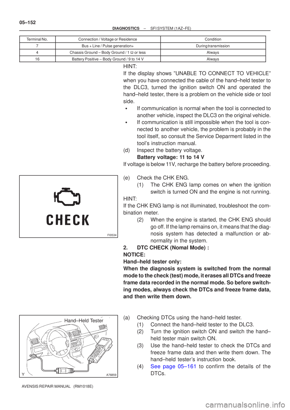
(e)Check the CHK ENG. (1)The CHK ENG lamp comes on when the ignitionswitch is turned ON and the engine is not running.
HINT:
If the CHK ENG lamp is not illuminated, troubleshoot the com-
bination meter. (2)When the engine is started, the CHK ENG shouldgo off. If the lamp remains on, it means that the diag-
nosis system has detected a malfunction or ab-
normality in the system.
2.DTC CHECK (Nomal Mode) :
NOTICE:
Hand±held tester only:
When the diagnosis system is switched from the normal
mode to the check (test) mode, it erases all DTCs and freeze
frame data recorded in the normal mode. So before switch-
ing modes, always check the DTCs and freeze frame data,
and then write them down.
(a)Checking DTCs using the hand±held tester. (1)Connect the hand±held tester to the DLC3.
(2)Turn the ignition switch ON and switch the hand±held tester main switch ON.
(3)Use the hand±held tester to check the DTCs and freeze frame data and then write them down. The
hand±held tester's instruction book.
(4)See page 05±161 to confirm the details of the DTCs.
Page 3889 of 5135
A76859
Hand±Held Tester
FI3605
ON
OFFBlinking
0.13 Second
05±154
± DIAGNOSTICSSFI SYSTEM (1AZ±FE)
AVENSIS REPAIR MANUAL (RM1018E)
3. DTC CHECK (Check Mode):
HINT:
Hand±held tester only:
Compared to the normal mode, the check mode has more sens-
ing ability to detect malfunctions.
Furthermore, the same diagnostic items which are detected in
the normal mode can also be detected in the check (test) mode.
(a) Proceduce for check mode using hand±held tester.
(1) Check the initial conditions
�Battery positive voltage 11V or more.
�Throttle valve fully closed.
�Transmission in the ºPº or ºNº position.
�Air conditioning switched OFF.
(2) Turn the ignition switch OFF.
(3) Connect the hand±held tester to the DLC3.
(4) Turn the ignition switch and the hand±held tester
main switch ON.
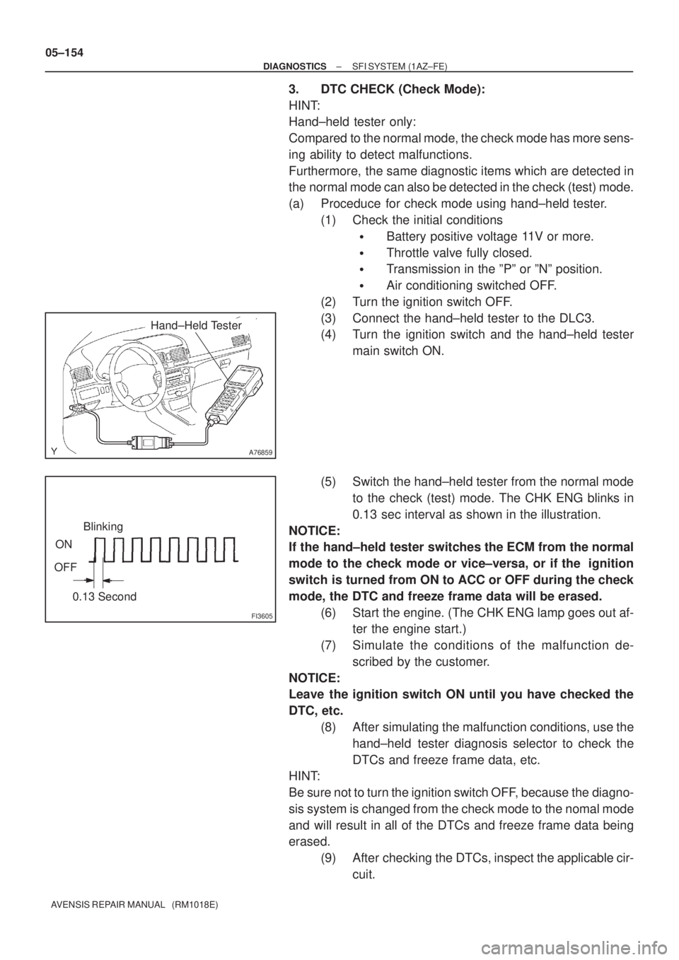
(5) Switch the hand±held tester from the normal mode
to the check (test) mode. The CHK ENG blinks in
0.13 sec interval as shown in the illustration.
NOTICE:
If the hand±held tester switches the ECM from the normal
mode to the check mode or vice±versa, or if the ignition
switch is turned from ON to ACC or OFF during the check
mode, the DTC and freeze frame data will be erased.
(6) Start the engine. (The CHK ENG lamp goes out af-
ter the engine start.)
(7) Simulate the conditions of the malfunction de-
scribed by the customer.
NOTICE:
Leave the ignition switch ON until you have checked the
DTC, etc.
(8) After simulating the malfunction conditions, use the
hand±held tester diagnosis selector to check the
DTCs and freeze frame data, etc.
HINT:
Be sure not to turn the ignition switch OFF, because the diagno-
sis system is changed from the check mode to the nomal mode
and will result in all of the DTCs and freeze frame data being
erased.
(9) After checking the DTCs, inspect the applicable cir-
cuit.