Page 251 of 5135

A79095
Battery FL
MAINB±Y
E12BATT
BR
E1 E9
IO1 1 EFI
7 7
3
EHECM Engine Room R/B No.1 and
Engine Room J/B No.1
2 1
1AB±Y
*1: LHD
*2: RHD IE37
*1
*2 1
Engine Room
J/B No.4 4A 1
4B 1B±G
B±G
± DIAGNOSTICSSFI SYSTEM (1ZZ±FE/3ZZ±FE)
05±119
AVENSIS REPAIR MANUAL (RM1018E)
DTC P1600 ECM BATT MALFUNCTION
CIRCUIT DESCRIPTION
Battery positive voltage is applied to terminal BATT of the ECM even the ignition switch is OFF for the DTC
memory and air±fuel ratio adaptive control value memory, etc.
DTC No.DTC Detecting ConditionTrouble Area
P1600Open in back up power source circuit�Open in back up power source circuit
� ECM
HINT:
If DTC P1600 is displayed, the ECM does not store other DTCs.
WIRING DIAGRAM
INSPECTION PROCEDURE
HINT:
Read freeze frame data using ��� �� ������ �����
� Freeze frame data records the engine conditions when
a malfunction is detected. When troubleshooting, it is useful for determining whether the vehicle was running
or stopped, the engine was warmed up or not, the air±fuel ratio was lean or rich, etc. at the time of the mal-
function.
05B49±02
Page 254 of 5135
± DIAGNOSTICSSFI SYSTEM (1ZZ±FE/3ZZ±FE)
05±115
AVENSIS REPAIR MANUAL (RM1018E)
DTC P1520 STOP LIGHT SWITCH CIRCUIT
MALFUNCTION
CIRCUIT DESCRIPTION
This signal is used to detect that the brakes have been applied. The STP signal voltage is the same as the
one supplied to the stop lights.
The STP signal is used mainly to control the fuel cut±off engine speed (The fuel cut±off engine speed is re-
duced slightly when the vehicle is braking.).
DTC No.DTC Detecting ConditionTrouble Area
P1520
Condition (a), (b) and (c) continue for 0.5 sec. or more:
(a) Ignition switch ON
(b) Brake pedal released
(c) STP signal is OFF when the STP signal is OFF�Open or short in stop light switch signal circuit
�Stop light switch
� ECM
05B48±02
Page 256 of 5135

05±117
AVENSIS REPAIR MANUAL (RM1018E)
INSPECTION PROCEDURE
HINT:
Read freeze frame data using ��� �� ������ �����
� Freeze frame data records the engine")
± DIAGNOSTICSSFI SYSTEM (1ZZ±FE/3ZZ±FE)
05±117
AVENSIS REPAIR MANUAL (RM1018E)
INSPECTION PROCEDURE
HINT:
Read freeze frame data using ��� �� ������ �����
� Freeze frame data records the engine conditions when
a malfunction is detected. When troubleshooting, it is useful for determining whether the vehicle was running
or stopped, the engine was warmed up or not, the air±fuel ratio was lean or rich, etc. at the time of the mal-
function.
1 CHECK OPERATION OF STOP LIGHT
(a) Check if the stop lights go on and off normally when the brake pedal is depressed and released.
NG REPAIR OR REPLACE STOP LAMP SWITCH
CIRCUIT
OK
2 READ VALUE OF HAND±HELD TESTER
(a) Connect the hand±held tester to the DLC3.
(b) Select the item ºDIAGNOSIS / OBD/MOBD / DATA LIST / ALL / STOP LIGHT SWº and read its value
displayed the hand±held tester.
(c) Turn the ignition switch ON and push the hand±held tester main switch ON.
(d) Read the STP signal on the hand±held tester.
Result:
Brake PedalSTP Signal
DepressedON
ReleasedOFF
OK CHECK FOR INTERMITTENT PROBLEMS
NG
Page 258 of 5135

AVENSIS REPAIR MANUAL (RM1018E)
DTCP1349VVT SYSTEM MALFUNCT")
A63991
ECM
C2
Camshaft Timing
Oil Control Valve
2
1
Y±B
W±G
OCV+
OCV±
15
14
E13
E13
05±112
±
DIAGNOSTICS SFI SYSTEM(1ZZ±FE/3ZZ±FE)
AVENSIS REPAIR MANUAL (RM1018E)
DTCP1349VVT SYSTEM MALFUNCTION (BANK 1)
CIRCUIT DESCRIPTION
VVT system controls the intake valve timing to proper timing in response to\
driving condition.
The ECM controls the oil control valve (OCV) to make the intake valve timing properly, oil pressure regulated
by the OCV is supplied to the valiable valve timing (VVT) controller, and then the VVT controller changes
relative position between the camshaft and the crankshaft.
DTC No.DTC Detecting ConditionTrouble Area
P1349
Condition (a) or (b) continues with engine speed at 400 to
4,000 rpm after the engine is warmed up
(a)Valve timing does not change from the current valve timing
(b)Current valve timing is fixed� Valve timing
� OCV
� VVT controller assembly
� ECM
WIRING DIAGRAM
INSPECTION PROCEDURE
HINT:
Read freeze frame data using \f���� ����\b�\f��\f�
� Freeze frame data records the engine conditions when
a malfunction is detected. When troubleshooting, it is useful for determi\
ning whether the vehicle was running
or stopped, the engine was warmed up or not, the air±fuel ratio was lea\
n or rich, etc. at the time of the mal-
function.
1CHECK VALVE TIMING (See page 14±49)
NGADJUST VALVE TIMING(See page 14±49)
OK
05C6F±01
Page 261 of 5135

05±103
AVENSIS REPAIR MANUAL (RM1018E)
DTC P1300 IGNITER CIRCUIT MALFUNCTION (NO.1)
DTC P1305 IGNITER CIRCUIT MALFUNCTION (NO.2)
DTC P1310 IGNITER CIRCUIT")
± DIAGNOSTICSSFI SYSTEM (1ZZ±FE/3ZZ±FE)
05±103
AVENSIS REPAIR MANUAL (RM1018E)
DTC P1300 IGNITER CIRCUIT MALFUNCTION (NO.1)
DTC P1305 IGNITER CIRCUIT MALFUNCTION (NO.2)
DTC P1310 IGNITER CIRCUIT MALFUNCTION (NO.3)
DTC P1315 IGNITER CIRCUIT MALFUNCTION (NO.4)
CIRCUIT DESCRIPTION
HINT:
�If DTC P1300 is displayed, check No.1 ignition coil with igniter circuit.
�If DTC P1305 is displayed, check No.2 ignition coil with igniter circuit.
�If DTC P1310 is displayed, check No.3 ignition coil with igniter circuit.
�If DTC P1315 is displayed, check No.4 ignition coil with igniter circuit.
A Direct Ignition System (DIS) has been adopted. The DIS improves the ignition timing accuracy, reduces
the high±voltage loss, and enhances overall reliability of the ignition system by eliminating the distributor.
The DIS is a 1±cylinder ignition system which ignites one cylinder with one ignition coil. In the 1±cylinder
ignition system, the spark plug is connected to the end of the secondary coil. High voltage generated in the
secondary coil is applied directly to the spark plug. The spark of the spark plug passes through from the cen-
ter electrode to the ground electrode.
The ECM determines ignition timing and outputs the ignition (IGT) signals of each cylinder. Based on IGT
signals, the power transistors cut off the current to the primary coil in the ignition coil. At the same time, the
igniter also sends an ignition confirmation (IGF) signal as a fail±safe measurement to the ECM.
05C6E±01
Page 262 of 5135
A73818
Crankshaft
Position
Sensor
Camshaft
Position
Sensor
Various
SensorIGT1
IGF
IGT2
IGT3
IGT4 ECM
No. 1 Spark Plug
No. 2 Spark Plug
No. 3 Spark Plug
No. 4 Spark Plug Ignition Coil
Assy No. 1 IgniterFrom Battery
Ignition Coil
Ignition Coil
Assy No. 2
Ignition Coil
Assy No. 3
Ignition Coil
Assy No. 4
TA C
To Tachometer 05±104
± DIAGNOSTICSSFI SYSTEM (1ZZ±FE/3ZZ±FE)
AVENSIS REPAIR MANUAL (RM1018E)DTC No.
DTC Detecting ConditionTrouble Area
P1300
P1305
P1310
P1315
No IGF signal to the ECM while engine is running
�Ignition system
�Open or short in IGF or IGT1 circuit from No. 1 ignition coil
with igniter to ECM
�No.1 ± No.4 ignition coil with igniter
� ECM
Page 265 of 5135
 GND (±)
Ignition Coil and Igniter Connector Wire Harness Side
I1
I2I3I4
A65743
E13
ECM Connector
IGT4IGT3
IGT2IGT1
IGF
A54393
IGT Wire Harness Side
Ignition Coil and Igniter ConnectorI")
A54393
+B (+) GND (±)
Ignition Coil and Igniter Connector Wire Harness Side
I1
I2I3I4
A65743
E13
ECM Connector
IGT4IGT3
IGT2IGT1
IGF
A54393
IGT Wire Harness Side
Ignition Coil and Igniter ConnectorIGF I1
I2I3I4
± DIAGNOSTICSSFI SYSTEM (1ZZ±FE/3ZZ±FE)
05±107
AVENSIS REPAIR MANUAL (RM1018E)
3 INSPECT IGNITION COIL(POWER SOURCE)
(a) Disconnect the ignition coil and igniter connector.
(b) Check for continuity between the wire harness side con-
nectors.
Standard (Check for open):
Symbols (Terminal No.)Specified condition
GND (I1±4) ± Body ground
GND (I2±4) ± Body groundContinuityGND (I3±4) ± Body groundContinuity
GND (I4±4) ± Body ground
(c) Turn the ignition switch ON.
(d) Measure the voltage between the terminals of the ignition
coil and igniter connector.
Standard:
Symbols (Terminal No.)Specified condition
+B (I1±1) ± GND (4)
+B (I2±1) ± GND (4)9to14V+B (I3±1) ± GND (4)9 to 14 V
+B (I4±1) ± GND (4)
NG Go to step 5
OK
4 CHECK HARNESS AND CONNECTOR(ECM ± IGNITION COIL)
HINT:
The procedure below is for No.1 cylinder. If a malfunction is
found on other cylinders, check the circuit for the cylinder with
referring to this procedure.
(a) Disconnect the ignition coil and igniter connector.
(b) Disconnect the E13 ECM connector.
(c) Check for continuity between the wire harness side con-
nectors.
Standard (Check for open):
Symbols (Terminal No.)Specified condition
IGT (I1±3) ± IGT1 (E13±8)
IGT (I2±3) ± IGT2 (E13±9)
IGT (I3±3) ± IGT3 (E13±10)
IGT (I4±3) ± IGT4 (E13±11)ContinuityIGF (I1±2) ± IGF (E13±23)Continuity
IGF (I2±2) ± IGF (E13±23)
IGF (I3±2) ± IGF (E13±23)
IGF (I4±2) ± IGF (E13±23)
Page 268 of 5135
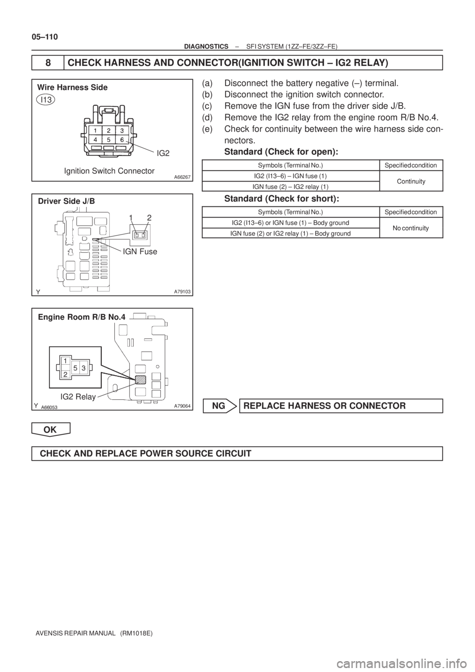
A66267
IG2 Wire Harness Side
Ignition Switch Connector
I13
A79103
Driver Side J/B
IGN Fuse12
������A79064
Engine Room R/B No.4
IG2 Relay
05±110
± DIAGNOSTICSSFI SYSTEM (1ZZ±FE/3ZZ±FE)
AVENSIS REPAIR MANUAL (RM1018E)
8 CHECK HARNESS AND CONNECTOR(IGNITION SWITCH ± IG2 RELAY)
(a) Disconnect the battery negative (±) terminal.
(b) Disconnect the ignition switch connector.
(c) Remove the IGN fuse from the driver side J/B.
(d) Remove the IG2 relay from the engine room R/B No.4.
(e) Check for continuity between the wire harness side con-
nectors.
Standard (Check for open):
Symbols (Terminal No.)Specified condition
IG2 (I13±6) ± IGN fuse (1)ContinuityIGN fuse (2) ± IG2 relay (1)Continuity
Standard (Check for short):
Symbols (Terminal No.)Specified condition
IG2 (I13±6) or IGN fuse (1) ± Body groundNo continuityIGN fuse (2) or IG2 relay (1) ± Body groundNo continuity
NG REPLACE HARNESS OR CONNECTOR
OK
CHECK AND REPLACE POWER SOURCE CIRCUIT

05±115
AVENSIS REPAIR MANUAL (RM1018E)
DTC P1520 STOP LIGHT SWITCH CIRCUIT
MALFUNCTION
CIRCUIT DESCRIPTION
This signal is used to detect that the brakes h")