Page 126 of 5135

± SERVICE SPECIFICATIONSFUEL
03±9
AVENSIS REPAIR MANUAL (RM1018E)Part Tightenedft�lbf kgf�cm N�m
Injection pipe clamp No. 2 x Intake manifold5.05144 in.�lbf
Fuel inlet pipe sub±assy x Common rail assy
Used pipe using SST
Used pipe not using SST
New pipe using SST
New pipe not using SST
42
46
31
34428
469
316
34731
34
23
25
Fuel inlet pipe sub±assy x Injection pump assy
Used pipe using SST
Used pipe not using SST
New pipe using SST
New pipe not using SST
42
46
31
34428
469
316
34731
34
23
25
Air cleaner case x Body7.07162 in.�lbf
Air cleaner case x Transverse engine engine mounting bracket7.07162 in.�lbf
Engine cover No. 1 x Cylinder head cover sub±assy8.08271 in.�lbf
Engine cover No. 1 x Intake manifold8.08271 in.�lbf
Vacuum reservoir sub±assy x Cowl top panel outer8.38574 in.�lbf
Injection pump assy x Water pump assy2121015
Injection pump drive pulley x Injection pump assy6465047
Intake manifold insulator No. 1 x Intake manifold5.05144 in.�lbf
Common rail assy x Cylinder head sub±assy4343832
Transverse engine engine mounting bracket x Water pump assy6465047
Transverse engine engine mounting bracket x Cylinder block sub±assy3737527
Idler pulley sub±assy x V±ribbed belt tensioner assy4040830
Battery clamp sub±assy x Body5.05144 in.�lbf
Front wheel1031,05076
Fuel filter assy x Fuel filter support1817813
DIESEL:
Part TightenedN�mkgf�cmft�lbf
Fuel tank band sub±assy x Body4040029
Parking brake cable assy x Body5.45548 in.�lbf
Fuel tank protector No. 1 x Body5.45548 in.�lbf
Fuel tank protector No. 1 x Fuel tank band sub±assy No. 15.45548 in.�lbf
Page 127 of 5135
031E0±01
± SERVICE SPECIFICATIONSFUEL
03±7
AVENSIS REPAIR MANUAL (RM1018E)
FUEL
SERVICE DATA
GASOLINE:
Compression spring
Free length Minimum Front x Manifold (1ZZ±FE/3ZZ±FE)
Front x Tail (1ZZ±FE/3ZZ±FE)
Center x Tail (1AZ±FE/1AZ±FSE)
41.5 mm (1.634 in.)
38.5 mm (1.516 in.)
38.5 mm (1.516 in.)
Page 128 of 5135

031DZ±02
03±6
± SERVICE SPECIFICATIONSENGINE CONTROL SYSTEM
AVENSIS REPAIR MANUAL (RM1018E)
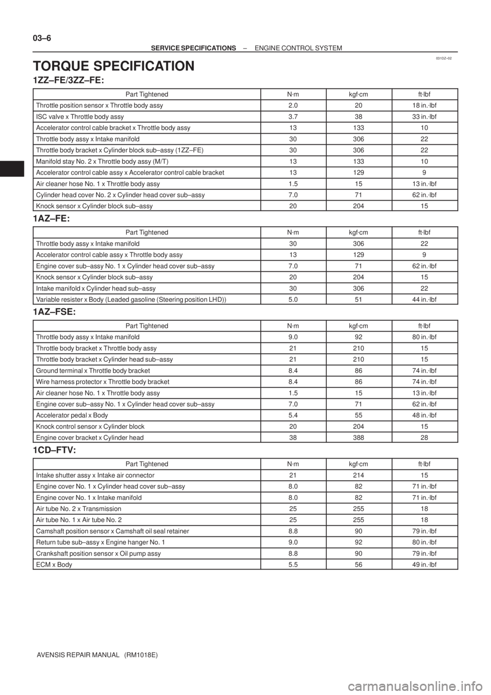
TORQUE SPECIFICATION
1ZZ±FE/3ZZ±FE:
Part TightenedN�mkgf�cmft�lbf
Throttle position sensor x Throttle body assy2.02018 in.�lbf
ISC valve x Throttle body assy3.73833 in.�lbf
Accelerator control cable bracket x Throttle body assy1313310
Throttle body assy x Intake manifold3030622
Throttle body bracket x Cylinder block sub±assy (1ZZ±FE)3030622
Manifold stay No. 2 x Throttle body assy (M/T)1313310
Accelerator control cable assy x Accelerator control cable bracket131299
Air cleaner hose No. 1 x Throttle body assy1.51513 in.�lbf
Cylinder head cover No. 2 x Cylinder head cover sub±assy7.07162 in.�lbf
Knock sensor x Cylinder block sub±assy2020415
1AZ±FE:
Part TightenedN�mkgf�cmft�lbf
Throttle body assy x Intake manifold3030622
Accelerator control cable assy x Throttle body assy131299
Engine cover sub±assy No. 1 x Cylinder head cover sub±assy7.07162 in.�lbf
Knock sensor x Cylinder block sub±assy2020415
Intake manifold x Cylinder head sub±assy3030622
Variable resister x Body (Leaded gasoline (Steering position LHD))5.05144 in.�lbf
1AZ±FSE:
Part TightenedN�mkgf�cmft�lbf
Throttle body assy x Intake manifold9.09280 in.�lbf
Throttle body bracket x Throttle body assy2121015
Throttle body bracket x Cylinder head sub±assy2121015
Ground terminal x Throttle body bracket8.48674 in.�lbf
Wire harness protector x Throttle body bracket8.48674 in.�lbf
Air cleaner hose No. 1 x Throttle body assy1.51513 in.�lbf
Engine cover sub±assy No. 1 x Cylinder head cover sub±assy7.07162 in.�lbf
Accelerator pedal x Body5.45548 in.�lbf
Knock control sensor x Cylinder block2020415
Engine cover bracket x Cylinder head3838828
1CD±FTV:
Part TightenedN�mkgf�cmft�lbf
Intake shutter assy x Intake air connector2121415
Engine cover No. 1 x Cylinder head cover sub±assy8.08271 in.�lbf
Engine cover No. 1 x Intake manifold8.08271 in.�lbf
Air tube No. 2 x Transmission2525518
Air tube No. 1 x Air tube No. 22525518
Camshaft position sensor x Camshaft oil seal retainer8.89079 in.�lbf
Return tube sub±assy x Engine hanger No. 19.09280 in.�lbf
Crankshaft position sensor x Oil pump assy8.89079 in.�lbf
ECM x Body5.55649 in.�lbf
Page 129 of 5135

031DY±01
03±4
± SERVICE SPECIFICATIONSENGINE CONTROL SYSTEM
AVENSIS REPAIR MANUAL (RM1018E)
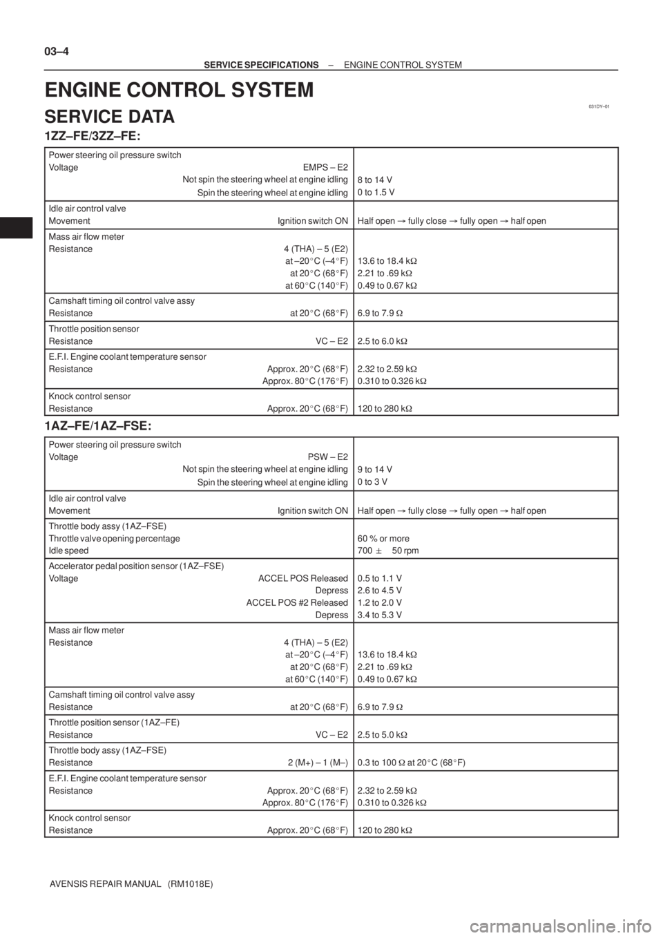
ENGINE CONTROL SYSTEM
SERVICE DATA
1ZZ±FE/3ZZ±FE:
Power steering oil pressure switch
Voltage EMPS ± E2
Not spin the steering wheel at engine idling
Spin the steering wheel at engine idling
8 to 14 V
0 to 1.5 V
Idle air control valve
Movement Ignition switch ON
Half open �fully close � fully open �half open
Mass air flow meter
Resistance 4 (THA) ± 5 (E2)
at ±20�C (±4�F)
at 20�C (68�F)
at 60�C (140�F)
13.6 to 18.4 k�
2.21 to .69 k�
0.49 to 0.67 k�
Camshaft timing oil control valve assy
Resistance at 20�C (68�F)
6.9 to 7.9 �
Throttle position sensor
Resistance VC ± E2
2.5 to 6.0 k�
E.F.I. Engine coolant temperature sensor
Resistance Approx. 20�C (68�F)
Approx. 80�C (176�F)
2.32 to 2.59 k�
0.310 to 0.326 k�
Knock control sensor
Resistance Approx. 20�C (68�F)
120 to 280 k�
1AZ±FE/1AZ±FSE:
Power steering oil pressure switch
Voltage PSW ± E2
Not spin the steering wheel at engine idling
Spin the steering wheel at engine idling
9 to 14 V
0 to 3 V
Idle air control valve
Movement Ignition switch ON
Half open �fully close � fully open �half open
Throttle body assy (1AZ±FSE)
Throttle valve opening percentage
Idle speed
60 % or more
700 �50 rpm
Accelerator pedal position sensor (1AZ±FSE)
Voltage ACCEL POS Released
Depress
ACCEL POS #2 Released
Depress
0.5 to 1.1 V
2.6 to 4.5 V
1.2 to 2.0 V
3.4 to 5.3 V
Mass air flow meter
Resistance 4 (THA) ± 5 (E2)
at ±20�C (±4�F)
at 20�C (68�F)
at 60�C (140�F)
13.6 to 18.4 k�
2.21 to .69 k�
0.49 to 0.67 k�
Camshaft timing oil control valve assy
Resistance at 20�C (68�F)
6.9 to 7.9 �
Throttle position sensor (1AZ±FE)
Resistance VC ± E2
2.5 to 5.0 k�
Throttle body assy (1AZ±FSE)
Resistance 2 (M+) ± 1 (M±)
0.3 to 100 � at 20�C (68�F)
E.F.I. Engine coolant temperature sensor
Resistance Approx. 20�C (68�F)
Approx. 80�C (176�F)
2.32 to 2.59 k�
0.310 to 0.326 k�
Knock control sensor
Resistance Approx. 20�C (68�F)
120 to 280 k�
Page 130 of 5135

±
SERVICE SPECIFICATIONS ENGINE CONTROL SYSTEM
03±5
AVENSIS REPAIR MANUAL (RM1018E)
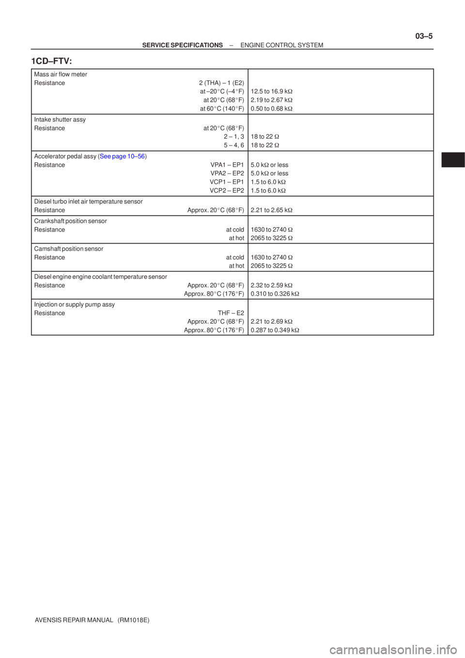
1CD±FTV:
Mass air flow meter
Resistance2 (THA) ± 1 (E2)
at ±20�C (±4 �F)
at 20 �C (68 �F)
at 60 �C (140 �F)
12.5 to 16.9 k �
2.19 to 2.67 k �
0.50 to 0.68 k �
Intake shutter assy
Resistanceat 20 �C (68 �F)
2 ± 1, 3
5 ± 4, 6
18 to 22 �
18 to 22 �
Accelerator pedal assy (See page 10±56)
Resistance VPA1 ± EP1
VPA2 ± EP2
VCP1 ± EP1
VCP2 ± EP2
5.0 k �or less
5.0 k �or less
1.5 to 6.0 k �
1.5 to 6.0 k �
Diesel turbo inlet air temperature sensor
Resistance Approx. 20 �C (68 �F)
2.21 to 2.65 k �
Crankshaft position sensor
Resistance at cold
at hot
1630 to 2740 �
2065 to 3225 �
Camshaft position sensor
Resistance at cold
at hot
1630 to 2740 �
2065 to 3225 �
Diesel engine engine coolant temperature sensor
Resistance Approx. 20 �C (68 �F)
Approx. 80 �C (176 �F)
2.32 to 2.59 k �
0.310 to 0.326 k �
Injection or supply pump assy
Resistance THF ± E2
Approx. 20�C (68 �F)
Approx. 80 �C (176 �F)
2.21 to 2.69 k �
0.287 to 0.349 k �
Page 131 of 5135
030LM±05
6N
8N
10N
11 N
12N
B06432
Nut Type
Present Standard
Hexagon Nut
Cold Forging Nut Cutting Processed NutClass
4N
5N (4T)
6N
7N (5T)
8N
10N (7T)
11 N
12N Old Standard Hexagon Nut
No Mark (w/ Washer)No Mark
*
No Mark (w/ Washer)
No Mark
No Mark
*: Nut with 1 or more marks on one side surface of the nut.
± SERVICE SPECIFICATIONSSTANDARD BOLT
03±3
AVENSIS REPAIR MANUAL (RM1018E)
HOW TO DETERMINE NUT STRENGTH
HINT:
Use the nut with the same number of the nut strength classification or the greater than the bolt strength clas-
sification number when tightening parts with a bolt and nut.
Example: Bolt = 4T
Nut = 4N or more
Page 132 of 5135

030LL±05
03±2
± SERVICE SPECIFICATIONSSTANDARD BOLT
AVENSIS REPAIR MANUAL (RM1018E)
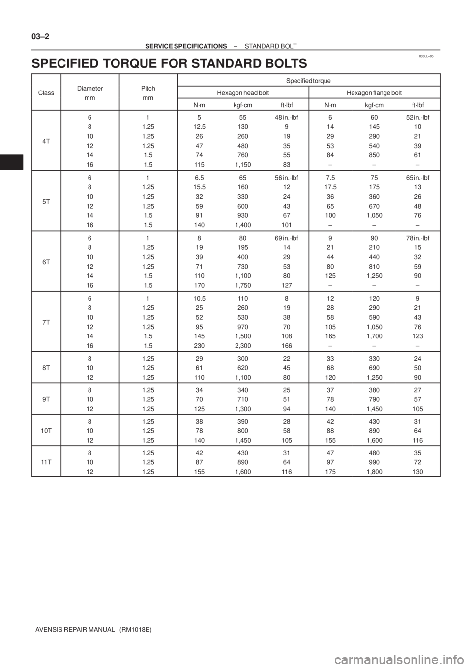
SPECIFIED TORQUE FOR STANDARD BOLTS
Specified torque
ClassDiameter
mm
Pitch
mmHexagon head boltHexagon flange boltmmmmN´mkgf´cmft´lbfN´mkgf´cmft´lbf
4T
6
8
10
12
14
161
1.25
1.25
1.25
1.5
1.55
12.5
26
47
74
11 555
130
260
480
760
1,15048 in.´lbf
9
19
35
55
836
14
29
53
84
±60
145
290
540
850
±52 in.´lbf
10
21
39
61
±
5T
6
8
10
12
14
161
1.25
1.25
1.25
1.5
1.56.5
15.5
32
59
91
14065
160
330
600
930
1,40056 in.´lbf
12
24
43
67
1017.5
17.5
36
65
100
±75
175
360
670
1,050
±65 in.´lbf
13
26
48
76
±
6T
6
8
10
12
14
161
1.25
1.25
1.25
1.5
1.58
19
39
71
11 0
17080
195
400
730
1,100
1,75069 in.´lbf
14
29
53
80
1279
21
44
80
125
±90
210
440
810
1,250
±78 in.´lbf
15
32
59
90
±
7T
6
8
10
12
14
161
1.25
1.25
1.25
1.5
1.510.5
25
52
95
145
23011 0
260
530
970
1,500
2,3008
19
38
70
108
16612
28
58
105
165
±120
290
590
1,050
1,700
±9
21
43
76
123
±
8T
8
10
121.25
1.25
1.2529
61
11 0300
620
1,10022
45
8033
68
120330
690
1,25024
50
90
9T
8
10
121.25
1.25
1.2534
70
125340
710
1,30025
51
9437
78
140380
790
1,45027
57
105
10T
8
10
121.25
1.25
1.2538
78
140390
800
1,45028
58
10542
88
155430
890
1,60031
64
11 6
11 T
8
10
121.25
1.25
1.2542
87
155430
890
1,60031
64
11 647
97
175480
990
1,80035
72
130
Page 133 of 5135
030LK±05
4
5
6
7
8
9
10
11
B06431
Bolt Type
Hexagon Head Bolt
Normal Recess Bolt Deep Recess BoltStud Bolt Weld BoltClass
4T
5T
6T
7T
8T
9T
10T
11 T
No Mark
w/ WasherNo MarkNo Mark
w/ Washer
± SERVICE SPECIFICATIONSSTANDARD BOLT
03±1
AVENSIS REPAIR MANUAL (RM1018E)
STANDARD BOLT
HOW TO DETERMINE BOLT STRENGTH