Page 1933 of 5135
±
FUEL FUEL PUMP ASSY(1AZ±FSE)
11±55
AVENSIS REPAIR MANUAL (RM1018E)
12.INSTALL ENGINE COVER BRACKET
(a)Install the engine cover bracket with the bolt.
Torque: 38 N �m (388 kgf �cm, 28 ft �lbf)
13.INSTALL AIR CLEANER CAP SUB±ASSY (See page 10±44)
14. CHECK FOR FUEL LEAKS
15. INSTALL ENGINE COVER SUB±ASSY NO.1 Torque: 7.0 N �m (71 kgf �cm, 62 in. �lbf)
16. INSTALL RADIATOR SUPPORT OPENING COVER
Page 1935 of 5135

1209H±02
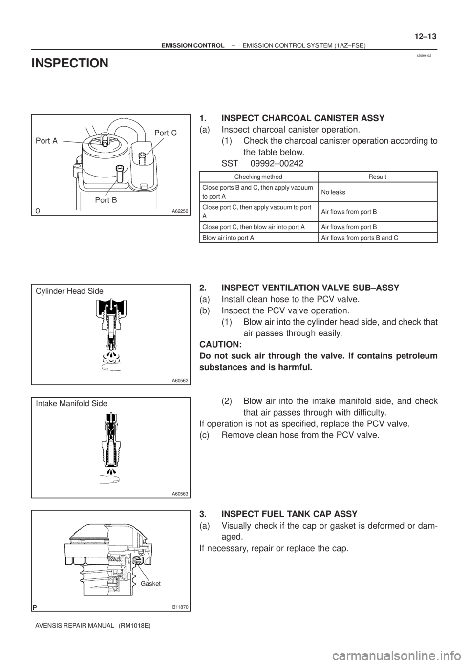
A62250
Port A
Port BPort C
A60562
Cylinder Head Side
A60563
Intake Manifold Side
Gasket
B11870
± EMISSION CONTROLEMISSION CONTROL SYSTEM (1AZ±FSE)
12±13
AVENSIS REPAIR MANUAL (RM1018E)
INSPECTION
1. INSPECT CHARCOAL CANISTER ASSY
(a) Inspect charcoal canister operation.
(1) Check the charcoal canister operation according to
the table below.
SST 09992±00242
Checking methodResult
Close ports B and C, then apply vacuum
to port ANo leaks
Close port C, then apply vacuum to port
AAir flows from port B
Close port C, then blow air into port AAir flows from port B
Blow air into port AAir flows from ports B and C
2. INSPECT VENTILATION VALVE SUB±ASSY
(a) Install clean hose to the PCV valve.
(b) Inspect the PCV valve operation.
(1) Blow air into the cylinder head side, and check that
air passes through easily.
CAUTION:
Do not suck air through the valve. If contains petroleum
substances and is harmful.
(2) Blow air into the intake manifold side, and check
that air passes through with difficulty.
If operation is not as specified, replace the PCV valve.
(c) Remove clean hose from the PCV valve.
3. INSPECT FUEL TANK CAP ASSY
(a) Visually check if the cap or gasket is deformed or dam-
aged.
If necessary, repair or replace the cap.
Page 1940 of 5135

1209F±02
A62250
Port A
Port BPort C
A60562
Cylinder Head Side
A60563
Intake Manifold Side
Gasket
B11870
12±8
± EMISSION CONTROLEMISSION CONTROL SYSTEM (1AZ±FE)
AVENSIS REPAIR MANUAL (RM1018E)
INSPECTION
1. INSPECT CHARCOAL CANISTER ASSY
(a) Inspect charcoal canister operation.
(1) Check the charcoal canister operation according to
the table below.
SST 09992±00242
Inspection:
Checking methodResult
Close ports B and C, then apply vacuum
to port ANo leaks
Close port C, then apply vacuum to port
AAir flows from port B
Close port C, then blow air into port AAir flows from port B
Blow air into port AAir flows from ports B and C
2. INSPECT VENTILATION VALVE SUB±ASSY
(a) Install clean hose to the PCV valve.
(b) Inspect the PCV valve operation.
(1) Blow air into the cylinder head side, and check that
air passes through easily.
CAUTION:
Do not suck air through the valve. If contains petroleum
substances and is harmful.
(2) Blow air into the intake manifold side, and check
that air passes through with difficulty.
If operation is not as specified, replace the PCV valve.
(c) Remove clean hose from the PCV valve.
3. INSPECT FUEL TANK CAP ASSY
(a) Visually check if the cap or gasket is deformed or dam-
aged.
If necessary, repair or replace the cap.
Page 1947 of 5135
B04812
Gasket
± EMISSION CONTROLEMISSION CONTROL SYSTEM (1ZZ±FE/3ZZ±FE)
12±5
AVENSIS REPAIR MANUAL (RM1018E)
5. INSPECT FUEL TANK CAP ASSY
(a) Visually check if the cap or gasket is deformed or dam-
aged.
Page 1992 of 5135
1306Z±01
A79155
A80093
A79158
±
INTAKE TURBOCHARGER SUB±ASSY(1CD±FTV)
13±11
AVENSIS REPAIR MANUAL (RM1018E)
REPLACEMENT
1.REMOVE ENGINE UNDER COVER SUB±ASSY NO.1
2.DRAIN ENGINE COOLANT(See page 16±44)
3.REMOVE RADIATOR SUPPORT OPENING COVER
4.REMOVE ENGINE COVER NO.1
(a)Remove the 5 nuts and the engine cover.
5.REMOVE VACUUM RESERVOIR SUB±ASSY
(a)Disconnect the 2 vacuum hoses and the connector.
(b)Remove the 2 bolts and the vacuum reservoir.
6.REMOVE AIR CLEANER ASSY
(a)Disconnect the PCV hose and the connector.
(b)Remove the air cleaner cap with the air cleaner hose.
(c)Remove the air cleaner filter element.
(d)Remove the 3 bolts and the air cleaner case. 7.REMOVE INTERCOOLER AIR HOSE
(a)Remove the 3 bolts and nut, separate the air tube No.1.
(b)Loosen the hose clamp bolts and remove the air hoseNo.1.
8.REMOVE FUEL FILTER ASSY(See page 11±82) 9. SEPARATE HEATER PUMP ASSY (W/ COLD AREA)
(a) Remove the nut and disconnect the connector.
(b) Separate the heater pump.
Page 2062 of 5135
A76702
Accelerator Control Cable Assy
Heater Inlet Water Hose
Fuel Pipe Clamp
Fuel Tube Sub±assy
Heater Outlet Water Hose
Air Cleaner Cap
W/ Hose
Air Cleaner Filter
Element Sub±assy
Air Cleaner Case Sub±assy Battery Clamp
Sub±assy
Battery
Battery Tray
Battery Carrier
12.8 (131, 9)
N´m (kgf´cm, ft´lbf)
: Specified torque
Union to Connector Tube Hose
Air Cleaner Clamp
Bracket
5.0 (51, 44 in.�lbf)
Fuel Vapor Feed Hose No.1
Fuel Vapor Feed Hose No.3
5.0 (51, 44 in.�lbf)
Oil Cooler
Inlet Hose
Oil Cooler
Outlet Hose
X4
VSV Connector
Mass Air Flow
Meter Connector
14±20
± ENGINE MECHANICALPARTIAL ENGINE ASSY (1ZZ±FE/3ZZ±FE)
AVENSIS REPAIR MANUAL (RM1018E)
Page 2124 of 5135
A76711
Fan and Generator V Belt
Generator Assy Terminal Cap
No. 1
Cylinder Head Cover No. 2 Clip
Fuel Pipe Clamp
Fuel Tube Sub±assy
Water By±pass Hose
Water By±pass Hose No. 2
Accelerator Control
Cable Assy
Heater Inlet Water Hose
Radiator Hose Inlet
Air Cleaner Hose No. 1
� GasketExhaust pipe Assy Front
Compression Spring43 (440, 32)
43 (440, 32)Compression Spring
� Non±reusable part
N´m (kgf´cm, ft´lbf) : Specified torque
V±ribbed idler Assy No. 1
Tube
54 (551, 40)
9.8 (100, 7)
25 (255, 18)
39 (400, 29)
7.0 (71, 62 in.�lbf)
52 (530, 38)
52 (530, 38)
Union to Connector Tube Hose
Fuel Vapor Feed Hose No.1
Fuel Vapor Feed Hose No.3
Vacuum Hose Assy
Engine
Mounting
Insulator RH
VSV Connector
Mass Air Flow Meter Connector
± ENGINE MECHANICALCYLINDER HEAD GASKET (1ZZ±FE/3ZZ±FE)
14±77
AVENSIS REPAIR MANUAL (RM1018E)
Page 2147 of 5135

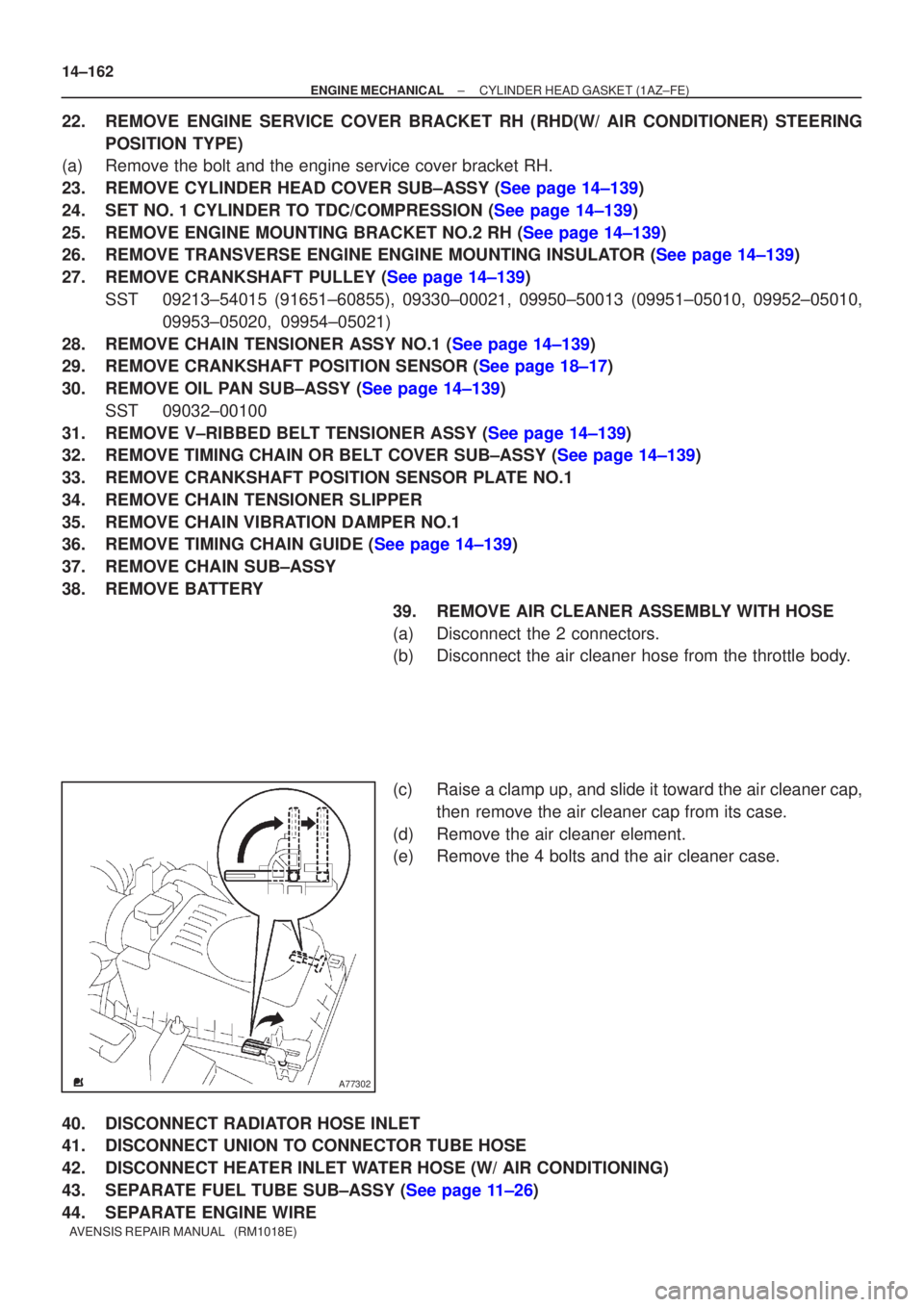
A77302
14±162
±
ENGINE MECHANICAL CYLINDER HEAD GASKET(1AZ±FE)
AVENSIS REPAIR MANUAL (RM1018E)
22.REMOVE ENGINE SERVICE COVER BRACKET RH (RHD(W/ AIR CONDITIONER) STEERING POSITION TYPE)
(a)Remove the bolt and the engine service cover bracket RH.
23.REMOVE CYLINDER HEAD COVER SUB±ASSY (See page 14±139)
24.SET NO. 1 CYLINDER TO TDC/COMPRESSION (See page 14±139)
25.REMOVE ENGINE MOUNTING BRACKET NO.2 RH (See page 14±139)
26.REMOVE TRANSVERSE ENGINE ENGINE MOUNTING INSULATOR (See page 14±139)
27.REMOVE CRANKSHAFT PULLEY (See page 14±139)
SST09213±54015 (91651±60855), 09330±00021, 09950±50013 (0995\
1±05010, 09952±05010, 09953±05020, 09954±05021)
28.REMOVE CHAIN TENSIONER ASSY NO.1 (See page 14±139)
29.REMOVE CRANKSHAFT POSITION SENSOR (See page 18±17)
30.REMOVE OIL PAN SUB±ASSY (See page 14±139) SST09032±00100
31.REMOVE V±RIBBED BELT TENSIONER ASSY (See page 14±139)
32.REMOVE TIMING CHAIN OR BELT COVER SUB±ASSY (See page 14±139)
33.REMOVE CRANKSHAFT POSITION SENSOR PLATE NO.1
34.REMOVE CHAIN TENSIONER SLIPPER
35.REMOVE CHAIN VIBRATION DAMPER NO.1
36.REMOVE TIMING CHAIN GUIDE (See page 14±139)
37.REMOVE CHAIN SUB±ASSY
38.REMOVE BATTERY 39.REMOVE AIR CLEANER ASSEMBLY WITH HOSE
(a)Disconnect the 2 connectors.
(b)Disconnect the air cleaner hose from the throttle body.
(c)Raise a clamp up, and slide it toward the air cleaner cap,then remove the air cleaner cap from its case.
(d)Remove the air cleaner element.
(e)Remove the 4 bolts and the air cleaner case.
40.DISCONNECT RADIATOR HOSE INLET
41.DISCONNECT UNION TO CONNECTOR TUBE HOSE
42.DISCONNECT HEATER INLET WATER HOSE (W/ AIR CONDITIONING)
43.SEPARATE FUEL TUBE SUB±ASSY (See page 11±26)
44. SEPARATE ENGINE WIRE