Page 4553 of 5135
![TOYOTA AVENSIS 2005 Service Repair Manual G23405Transmission Wire
− DIAGNOSTICSELECTRONIC CONTROLLED AUTOMATIC
TRANSAXLE [ECT] (U151E)05−539
AVENSIS Supplement (RM1045E)
(9) Disconnect the connector of the transmission wire.
HINT:
Disconn TOYOTA AVENSIS 2005 Service Repair Manual G23405Transmission Wire
− DIAGNOSTICSELECTRONIC CONTROLLED AUTOMATIC
TRANSAXLE [ECT] (U151E)05−539
AVENSIS Supplement (RM1045E)
(9) Disconnect the connector of the transmission wire.
HINT:
Disconn](/manual-img/14/57441/w960_57441-4552.png)
G23405Transmission Wire
− DIAGNOSTICSELECTRONIC CONTROLLED AUTOMATIC
TRANSAXLE [ECT] (U151E)05−539
AVENSIS Supplement (RM1045E)
(9) Disconnect the connector of the transmission wire.
HINT:
Disconnect the connector only when performing the D position
stall test.
(10) Start the engine.
(11) Firmly depress the brake pedal, shift to the D posi-
tion, depress the accelerator pedal all the way down
and check the line pressure while the stall test is
performed.
Specified line pressure:
ConditionD position
Stall test931to1,031kPa
(9.5 to10.5 kgf/cm2,135 to150 psi)
(12) Turn the ignition switch off.
(13) Remove the SST, install the test plug A.
(14) Remove the test plug B, install the SST and start en-
gine.
SST 09992−00095 (09992−00231, 09992−00271)
(15) Connect the transmission wire connector, depress
the brake pedal firmly, shift to the R position and
check that the line pressure while the engine is id-
ling and during the stall test.
Specified line pressure:
ConditionR position
Idling672 to 742 kPa
(6.9 to 7.6 kgf/cm2,97to108 psi)
Stall test1,768 to1,968 kPa
(18.0 to 20.1kgf/cm2, 256 to 285 psi)
(16) Remove the SST, install the test plug B.
(17) Clear the DTC.
Evaluation:
ProblemPossible cause
If the measured values at all position are higherSShift solenoid valve (SLT) defective
SRegulator valve defective
If the measured values at all position are lower
SShift solenoid valve (SLT) defective
SRegulator valve defective
SOil pump defective
SU/D (Underdrive) direct clutch defective
If pressure is low in the D position onlySD position circuit fluid leak
SForward clutch defective
If pressure is low in the R position only
SR position circuit fluid leak
SReverse clutch defective
S1st and reverse brake defective
Page 4590 of 5135

1111 4−01
A88253
(a)
(b)
Pull Out
A88252
(a)
(b)
(c)
(d)
A77920
RHD:
LHD:
−
FUEL FUEL INJECTOR ASSY (2AZ −FSE)
11 −13
AVENSIS Supplement (RM1045E)
REPLACEMENT
1. DISCHARGE FUEL SYSTEM PRESSURE (See page 11 −1)
2. REMOVE RADIATOR SUPPORT OPENING COVER (See page 10 −8)
3. REMOVE ENGINE ROOM COVER SIDE (See page 10 −8)
4. DISCONNECT ENGINE WIRE NO.3 (BATTERY NEGATIVE TERMINAL)
5. DRAIN ENGINE COOLANT (See page 16 −7)
6. REMOVE ENGINE COVER SUB −ASSY NO.1 (See page 10 −8)
7. REMOVE AIR CLEANER CAP SUB −ASSY (See page 10 −8)
8. REMOVE THROTTLE BODY ASSY (See page 10 −8)
9. REMOVE FUEL TUBE SUB −ASSY (See page 11 −24)
SST 09617 −24011
10. REMOVE FUEL HOSE (See page 11 −24)
11. REMOVE FUEL PIPE SUB −ASSY NO.1 (See page 11 −24)
SST 09023 −12900
12. REMOVE FUEL PUMP ASSY (See page 11 −24)
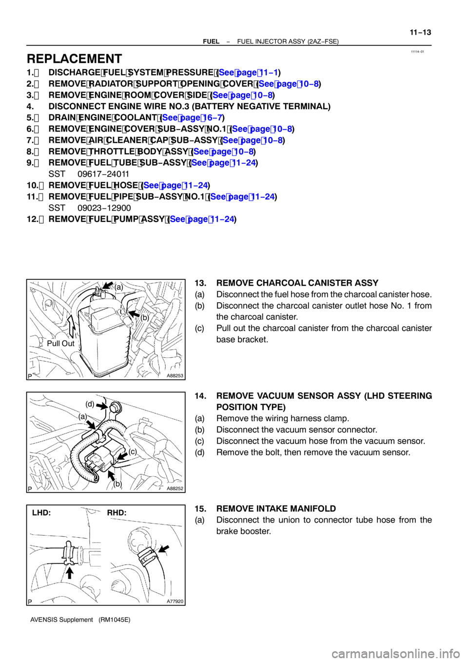
13. REMOVE CHARCOAL CANISTER ASSY
(a) Disconnect the fuel hose from the charcoal canister hose.
(b) Disconnect the charcoal canister outlet hose No. 1 from the charcoal canister.
(c) Pull out the charcoal canister from the charcoal canister base bracket.
14. REMOVE VACUUM SENSOR ASSY (LHD STEERING POSITION TYPE)
(a) Remove the wiring harness clamp.
(b) Disconnect the vacuum sensor connector.
(c) Disconnect the vacuum hose from the vacuum sensor.
(d) Remove the bolt, then remove the vacuum sensor.
15. REMOVE INTAKE MANIFOLD
(a) Disconnect the union to connector tube hose from the
brake booster.
Page 4596 of 5135

A88257
12345
A88256
(i)
(j)
(i)
−
FUEL FUEL INJECTOR ASSY (2AZ −FSE)
11 −19
AVENSIS Supplement (RM1045E)
(g) Using a Torx socket E7, install and tighten the 2 stud bolts
to secure the intake manifold, intake air control valve and
gasket.
Torque: 9.5 N �m (97 kgf �cm, 84 in. �lbf)
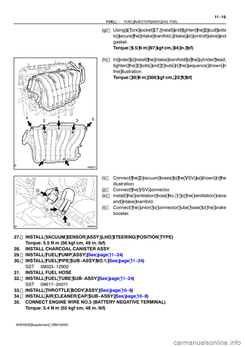
(h) In order to install the intake manifold to the cylinder head, tighten the 3 bolts and 2 nuts in the sequence shown in
the illustration.
Torque: 30 N �m (306 kgf �cm, 22 ft �lbf)
(i) Connect the 2 vacuum hoses to the VSV as shown in the illustration.
(j) Connect the VSV connector.
(k) Install the ventilation hose No. 1 to the ventilation valve and intake manifold.
(l) Connect the union to connector tube hose to the brake booster.
27. INSTALL VACUUM SENSOR ASSY (LHD STEERING POSITION TYPE) Torque: 5.5 N �m (56 kgf �cm, 49 in. �lbf)
28. INSTALL CHARCOAL CANISTER ASSY
29. INSTALL FUEL PUMP ASSY (See page 11 −24)
30. INSTALL FUEL PIPE SUB −ASSY NO.1 (See page 11 −24)
SST 09023 −12900
31. INSTALL FUEL HOSE
32. INSTALL FUEL TUBE SUB −ASSY (See page 11 −24)
SST 09617 −24011
33. INSTALL THROTTLE BODY ASSY (See page 10 −8)
34. INSTALL AIR CLEANER CAP SUB −ASSY (See page 10 −8)
35. CONNECT ENGINE WIRE NO.3 (BATTERY NEGATIVE TERMINAL) Torque: 5.4 N �m (55 kgf �cm, 48 in. �lbf)
Page 4675 of 5135

A87967
Upward90_
Clamp
Bolt
Turbocharger Side:
Air Hose No. 2 Side:
Front 90
_ Clamp Bolt
20.4_
14
−134
−
ENGINE MECHANICAL PARTIAL ENGINE ASSY (1CD −FTV)(From September,
2003)
AVENSIS Supplement (RM1045E)
(b) Tighten the 2 hose clamps as shown in the illustration. Torque: 6.0 N �m (61 kgf �cm, 53 in. �lbf)
(c) Install the air tube No. 1 with the 3 bolts and nut. Torque: 25 N �m (255 kgf �cm, 18 ft �lbf)
208. INSTALL DIFFERENTIAL PRESSURE SENSOR ASSY Torque: 5.5 N �m (56 kgf �cm, 49 in. �lbf)
209. INSTALL RADIATOR ASSY (W/ AIR CONDITIONING) (See Pub. No. RM1018E on page 16 −51)
210. INSTALL ENGINE ROOM RELAY BLOCK NO.3
Torque: 5.3 N �m (54 kgf �cm, 47 in. �lbf)
211. INSTALL FUEL FILTER ASSY (See Pub. No. RM1018E on page 11 −82)
212. INSTALL AIR CLEANER ASSY Torque: 7.0 N �m (71 kgf �cm, 62 in. �lbf)
213. INSTALL BATTERY Torque:
5.0 N�m (51 kgf �cm, 44 in. �lbf) for bolt
3.0 to 4.0 N �m (31 to 41 kgf �cm, 27 to 35 in. �lbf) for nut
5.4 N �m (55 kgf �cm, 48 in. �lbf) for terminal
214. INSTALL ENGINE COVER SUB −ASSY NO.1
Torque: 8.0 N �m (82 kgf �cm, 71 in. �lbf)
215. BLEED CLUTCH PIPE LINE (See Pub. No. RM1018E on page 42 −12)
216. INSTALL FRONT WHEELS
Torque: 103 N �m (1,050 kgf �cm, 76 ft �lbf)
217. ADD MANUAL TRANSAXLE OIL (See Pub. No. RM1018E on page 41 −5)
218. ADD ENGINE OIL (See Pub. No. RM1018E on page 17 −30)
219. ADD ENGINE COOLANT (See page 16 −19)
220. CHECK CLUTCH FLUID LEAKAGE
221. CHECK FLUID LEVEL IN RESERVOIR
222. CHECK BRAKE FLUID LEAKAGE
223. CHECK FOR ENGINE OIL LEAKS
224. CHECK FOR FUEL LEAKS (See page 11 −46)
225. CHECK FOR ENGINE COOLANT LEAKS (See page 16 −15)
226. CHECK FOR EXHAUST GAS LEAKS
227. INSPECT AND ADJUST FRONT WHEEL ALIGNMENT (See Pub. No. RM1018E on page 26 −6)
Page 4726 of 5135
3211F−01
G24211
F46213
To Master
Cylinder Rear
To
Master
Cylinder
Front
To Rear Wheel
RH
To Front Wheel LH
To Front Wheel RH
To Rear Wheel
LH
−
BRAKE BRAKE BOOSTER ASSY (RHD) (2AZ −FSE)
32 −3
AVENSIS Supplement (RM1045E)
REPLACEMENT
NOTICE:
Do not adjust the brake booster push rod.
1. DRAIN BRAKE FLUID
NOTICE:
Wash the brake fluid off immediately if it adheres to any painted surface.
2. REMOVE FRONT WHEEL RH
3. REMOVE ENGINE COVER NO. 1
4. REMOVE CYLINDER HEAD COVER SUB −ASSY (SEE PAGE 14− 79)
5. REMOVE IGNITION COIL ASSY (SEE PAGE 14− 79)
6. REMOVE ENGINE ASSEMBLY WITH TRANSAXLE (SEE PAGE 14− 23)
7. REMOVE BRAKE MASTER CYLINDER SUB −ASSY
SST 09023 −00100
8. REMOVE BRAKE TUBE
(a) Using SST, disconnect the 6 brake tubes from the brakeactuator.
SST 09023 −00100
(b) Use tags or make a memo to identify the place to recon- nect.
Page 4727 of 5135
C80802
C80806
F45361F46832
F45362F46833
F46183
32−4
− BRAKEBRAKE BOOSTER ASSY (RHD) (2AZ−FSE)
AVENSIS Supplement (RM1045E)
(c) Using SST and a spanner, disconnect the brake tube from
the flexible hose of the front brake RH.
SST 09023−00100
(d) Remove the 2 bolts and disconnect the 2 brake tube
clamps.
(e) Using SST, disconnect the 3 brake tubes from the ways.
SST 09023−00100
(f) Disconnect the clamp from the stud bolt and remove the
brake tubes.
9. REMOVE BRAKE BOOSTER ASSY
(a) Disconnect the vacuum hose from the brake booster
assy.
(b) Remove the clip, the clevis pin and the wave washer.
Page 4728 of 5135

C80805
C80805
F46183
F45362F46833
− BRAKEBRAKE BOOSTER ASSY (RHD) (2AZ−FSE)
32−5
AVENSIS Supplement (RM1045E)
(c) Remove the 4 nuts.
(d) Pull out the brake booster assy.
(e) Remove the brake master cylinder clevis from the brake
booster assy.
10. REMOVE BRAKE BOOSTER GASKET
(a) Pull out the brake booster gasket.
11. REMOVE CHECK VALVE
(a) Remove the check valve and grommet from the brake booster assy.
12. INSTALL CHECK VALVE
(a) Install the check valve and grommet to the brake booster assy.
13. INSTALL BRAKE BOOSTER GASKET
(a) Install a new brake booster gasket to the brake booster assy.
14. INSTALL BRAKE BOOSTER ASSY
(a) Install the brake master cylinder clevis to the brake boost-
er assy.
Torque: 22 N�m (224 kgf�cm,16ft�lbf)
(b) Install the brake booster assy with the 4 nuts.
Torque:13N�m(133 kgf�cm,10ft�lbf)
(c) Install the clevis pin, the clip and the wave washer.
(d) Connect the vacuum hose to the check valve.
15. INSTALL BRAKE TUBE
(a) Connect the clamp to the stud bolt.
Page 4729 of 5135
F45361F46832
C80802
F46213
To Master
Cylinder Rear
To
Master
Cylinder
Front
To Rear Wheel
RH
To Front Wheel LH
To Front Wheel RH
To Rear Wheel
LH
C80806
32−6
−
BRAKE BRAKE BOOSTER ASSY (RHD) (2AZ −FSE)
AVENSIS Supplement (RM1045E)
(b) Using SST, connect the 3 brake tubes to the ways. SST 09023 −00100
Torque: 15N �m( 155 kgf �cm, 11 ft �lbf)
(c) Using SST and a spanner, connect the brake tube to the flexible hose of front brake RH.
SST 09023 −00100
Torque: 15N �m( 155 kgf �cm, 11 ft �lbf)
(d) Using SST, connect the 6 brake tubes to the brake actua- tor, as shown in the illustration.
SST 09023 −00100
Torque: 15N �m( 155 kgf �cm, 11 ft �lbf)
(e) Install the brake tube clamps with the 2 bolts. Torque: 6.0 N �m(6 1 kgf �cm, 53 in. �lbf)
1 6. INSTALL BRAKE MASTER CYLINDER SUB −ASSY
SST 09023 −00100
1 7. INSTALL ENGINE ASSEMBLY WITH TRANSAXLE (SEE PAGE 14− 23)
1 8. INSTALL IGNITION COIL ASSY (SEE PAGE 14− 79)
1 9. INSTALL CYLINDER HEAD COVER SUB −ASSY (SEE PAGE 14− 79)