Page 313 of 5135

A79082
53G±Y
L±B E9 10
4
5 W±B
BR F25
Fuel Pump ECM
B±W 12
FC
C8
Circuit
Opening Relay
From
Terminal 3 of
EFI Relay
(See Page 05±124)
G±Y
B±W
B±W
IB1 10 IC3
6
±
DIAGNOSTICS SFI SYSTEM(1ZZ±FE/3ZZ±FE)
05±131
AVENSIS REPAIR MANUAL (RM1018E)
FUEL PUMP CONTROL CIRCUIT
CIRCUIT DESCRIPTION
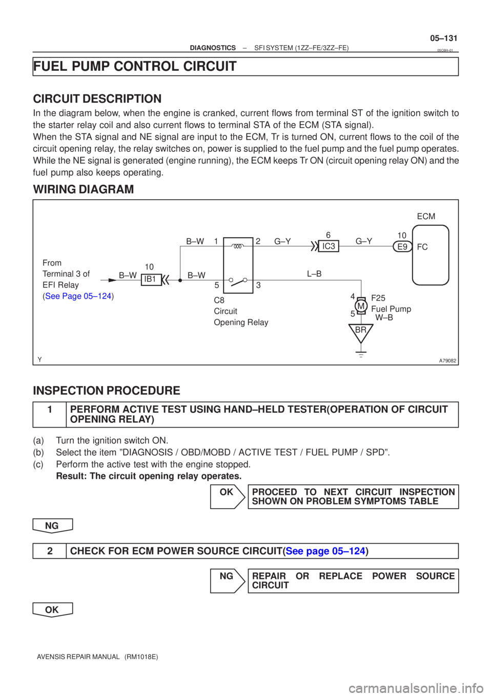
In the diagram below, when the engine is cranked, current flows from terminal ST of the igni\
tion switch to
the starter relay coil and also current flows to terminal STA of the ECM (STA signal).
When the STA signal and NE signal are input to the ECM, Tr is turned ON, current flows to the coil of the
circuit opening relay, the relay switches on, power is supplied to the fuel pump and the fuel p\
ump operates.
While the NE signal is generated (engine running), the ECM keeps Tr ON (circuit opening relay ON) and the
fuel pump also keeps operating.
WIRING DIAGRAM
INSPECTION PROCEDURE
1PERFORM ACTIVE TEST USING HAND±HELD TESTER(OPERATION OF CIRCUIT
OPENING RELAY)
(a)Turn the ignition switch ON.
(b)Select the item ºDIAGNOSIS / OBD/MOBD / ACTIVE TEST / FUEL PUMP / SPD\
º.
(c)Perform the active test with the engine stopped.
Result: The circuit opening relay operates.
OKPROCEED TO NEXT CIRCUIT INSPECTIONSHOWN ON PROBLEM SYMPTOMS TABLE
NG
2CHECK FOR ECM POWER SOURCE CIRCUIT(See page 05±124)
NG REPAIR OR REPLACE POWER SOURCE CIRCUIT
OK
05C6H±01
Page 318 of 5135
A79085
IE4
IP1
1 1 B±R
4
6
I13
Ignition Switch
B±RDH IGN
16 DL
2
Driver Side J/B
B±W
B
B±R 4
4
1
IG2
Relay
2
3 Engine Room
R/B No.4 ECM
4 4
5
111 B±Y
2
1 112
2
EFI
IG2
AM2
1A B±G Engine Room
R/B No.1 and
Engine Room
J/B No.1 R±B
EA1
8 8
MREL
E9
GR
IE1
2
GR
4
4
51
32 EFI
Relay
4 4
Engine Room
R/B No.4
W±B
W±B
1
1+B
E9
B±R
EC
To Injector
(See page 05±73)
To Ignition Coil
and Igniter
(See page 05±103)
B±R
B±R
EA1
IK1
8
12
Battery
FL MAIN
B±G Engine Room
J/B No.4
4A
4B
1
1
R±B
W±B EFI
No.1
Engine Room
R/B No.4
1 B±W
4
2 4
18
DA B±W
A
J26
Junction Connector
E
J27 B±W
E9IGSW
9
(*2) J8
Junction Connector
(*1) B±W
EH E1
7
E12
BR
(*2)
(*1)
C C
*1: RHD *2: LHD
(*1)
(*2)
±
DIAGNOSTICS SFI SYSTEM (1ZZ±FE/3ZZ±FE)
05±125
AVENSIS REPAIR MANUAL (RM1018E)
WIRING DIAGRAM
Page 324 of 5135

���\b�A79115
Reference (Bank 1 Sensor 2 System Drawing)Heated Oxygen Sensor
EFI Relay
Heater
SensorOX1B HT1BECM
From
Battery EFI Fuse
O1B±
MREL
EFI No.2 Fuse
05±218
±
DIAGNOSTICS SFI SYSTEM(1AZ±FE)
AVENSIS REPAIR MANUAL (RM1018E)
DTCP0141/27OXYGEN SENSOR HEATER CIRCUIT MALFUNCTION (BANK 1 SENSOR 2)
DTCP0161/29OXYGEN SENSOR HEATER CIRCUIT (BANK 2 SENSOR 2)
CIRCUIT DESCRIPTION
Refer to DTC P0136/27 on page 05±211.
HINT:
The ECM provides a pulse width modulated control circuit to adjust current \
through the heater. The heated
oxygen sensor heater circuit uses a relay on the B+ side of the circuit.
DTC No.DTC Detection ConditionTrouble Area
P0141/27
Heated current is 0.2 A or less when heater operates
(1 trip detection logic)�Open or short in heater circuit of heated oxygen sensor
� Heated oxygen sensor heater
P0141/27
P0161/29When heater operates, heated current exceeds 2 A
(1 trip detection logic)
yg
�EFI relay
� ECM
HINT:
�Bank 1 refers to the bank that includes cylinder No.1.
�Bank 2 refers to the bank that does not include cylinder No.1.
�Sensor 1 refers to the sensor closest to the engine assembly.
�Sensor 2 refers to the sensor farthest away from the engine assembly.
WIRING DIAGRAM
Refer to DTC P0136/27 on page 05±211.
INSPECTION PROCEDURE
HINT:
�If different DTCs that are related to a different system are output simultaneously while terminal E2 is
used as a ground terminal, terminal E2 may be open.
�Read freeze frame data using �
\f
���
\f�� �\f��\f�� Freeze frame data records the engine conditions
when a malfunction is detected. When troubleshooting, it is useful for d\
etermining whether the vehicle
was running or stopped, the engine was warmed up or not, the air±fuel ra\
tio was lean or rich, etc. at
the time of the malfunction.
05C6Y±01
Page 329 of 5135
A76884
B±W
GR GR2
IE1
E98ECM
MREL
44
31Engine Room R/B No.4
4EFI No.2
4
1
2B±W
EA113
B±W
52EFI
RelayEngine Room
R/B No.4
44H8
Heated Oxygen Sensor
(Bank 1 Sensor 2)
2
43 1IK14
L4
E10HT1B
21
E12 OX1B
32
E13O1B± WB
(*1) B±W
B±WH10
Heated Oxygen Sensor
(Bank 2 Sensor 2)
21L±R10
IK1L±R3
HT2B
E10 J12BR
D
J/C EFI 2
1
1A 11B±YW±B
Engine
Room
R/B No.1
Engine
Room
J/B No.1
43R
G
(*1)29
OX2B E12
O2B± 31
E13
*1: Shielded
EF ECBR J12 J/CJ13BR
D
EJ13
E B±G
Engine Room
J/B No.4 4A
4B 1 1
B±G
FL MAIN
BatteryL 05±212
± DIAGNOSTICSSFI SYSTEM (1AZ±FE)
AVENSIS REPAIR MANUAL (RM1018E)
HINT:
�Bank 1 refers to the bank that includes cylinder No.1.
�Bank 2 refers to the bank that does not include cylinder No.1.
�Sensor 2 refers to the sensor farthest away from the engine assembly.
WIRING DIAGRAM
Page 336 of 5135
A12544
VCECM
VTA1
E2 L±W R±W
BR T2
Throttle Position Sensor
1
3
218
E13
21
E13
28
E13 VC
E2 VTA5V
E1
± DIAGNOSTICSSFI SYSTEM (1AZ±FE)
05±205
AVENSIS REPAIR MANUAL (RM1018E)Throttle valve opening position expressed as percentage
Trouble AreaThrottle valve fully closedThrottle valve fully openTrouble Area
0 %0 %VC circuit open
VTA circuit open or short
Approx. 100 %Approx. 100 %E2 circuit open
WIRING DIAGRAM
INSPECTION PROCEDURE
HINT:
�Read freeze frame data using ��� �� ������ �����
� Freeze frame data records the engine conditions
when a malfunction is detected. When troubleshooting, it is useful for determining whether the vehicle
was running or stopped, the engine was warmed up or not, the air±fuel ratio was lean or rich, etc. at
the time of the malfunction.
�If different DTCs that are related to a different system are output simultaneously while terminal E2 is
used as a ground terminal, terminal E2 may be open.
Page 342 of 5135

A72925
ECM
THW
E2 19
E13
28
E13 BR B±W
1 25V
R E2
Engine Coolant Temperature Sensor
± DIAGNOSTICSSFI SYSTEM (1AZ±FE)
05±199
AVENSIS REPAIR MANUAL (RM1018E)
DTC P0115/22 ENGINE COOLANT TEMPERATURE CIRCUIT
DTC P0117/22 ENGINE COOLANT TEMPERATURE CIRCUIT
LOW INPUT
DTC P0118/22 ENGINE COOLANT TEMPERATURE CIRCUIT
HIGH INPUT
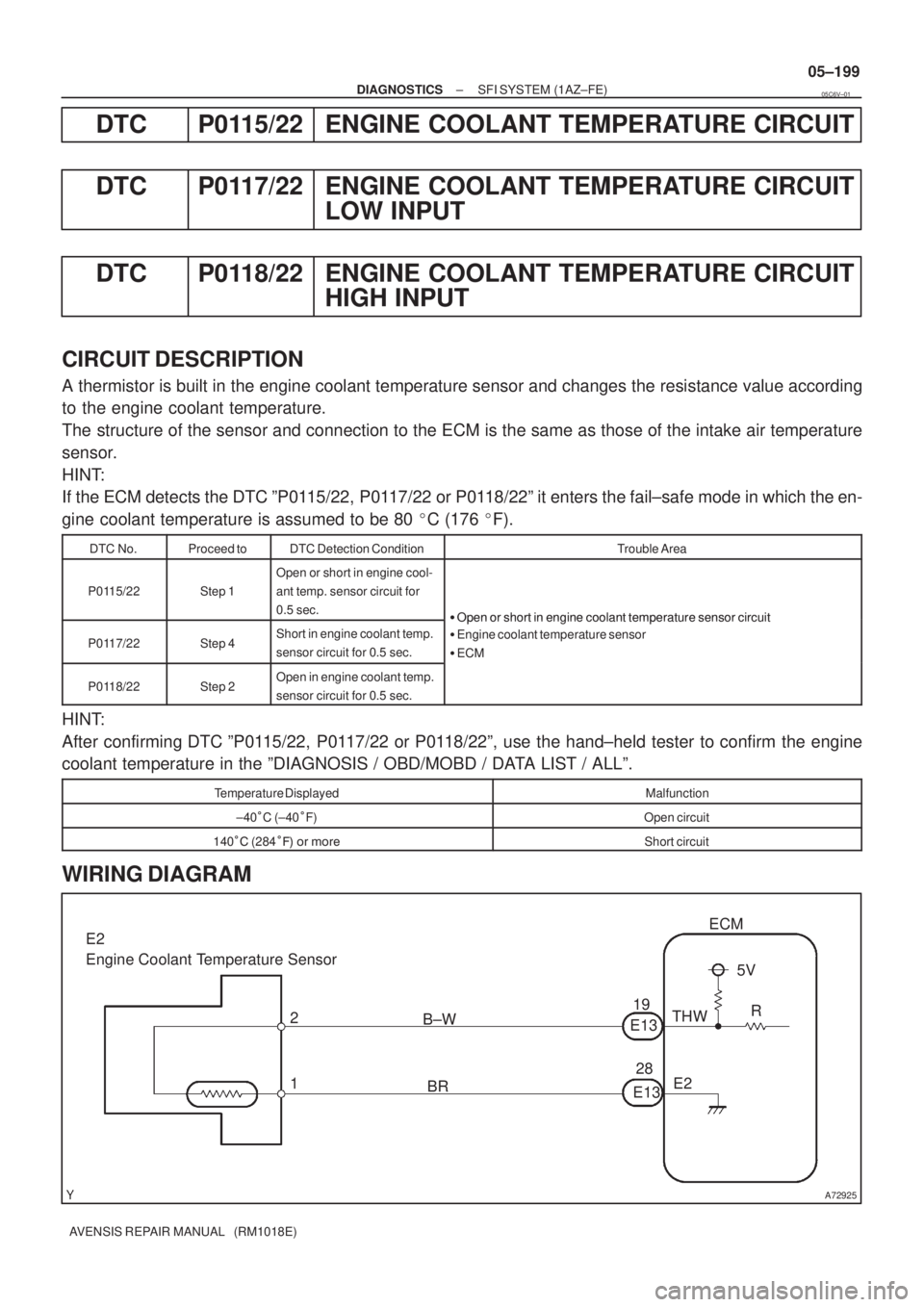
CIRCUIT DESCRIPTION
A thermistor is built in the engine coolant temperature sensor and changes the resistance value according
to the engine coolant temperature.
The structure of the sensor and connection to the ECM is the same as those of the intake air temperature
sensor.
HINT:
If the ECM detects the DTC ºP0115/22, P0117/22 or P0118/22º it enters the fail±safe mode in which the en-
gine coolant temperature is assumed to be 80 �C (176 �F).
DTC No.Proceed toDTC Detection ConditionTrouble Area
P0115/22Step 1
Open or short in engine cool-
ant temp. sensor circuit for
0.5 sec.
�Open or short in engine coolant temperature sensor circuit
P0117/22Step 4Short in engine coolant temp.
sensor circuit for 0.5 sec.
�Open or short in engine coolant temperature sensor circuit
�Engine coolant temperature sensor
�ECM
P0118/22Step 2Open in engine coolant temp.
sensor circuit for 0.5 sec.
HINT:
After confirming DTC ºP0115/22, P0117/22 or P0118/22º, use the hand±held tester to confirm the engine
coolant temperature in the ºDIAGNOSIS / OBD/MOBD / DATA LIST / ALLº.
Temperature DisplayedMalfunction
±40 C (±40 F)Open circuit
140 � (284 �� �� ����Short circuit
WIRING DIAGRAM
05C6V±01
Page 348 of 5135

A72925
BR
G±R
28
20
E13 THA
E2 ECM
5 4
A6
Intake Air Temperature Sensor
(Built in Mass Air Flow Meter)
E135V
R
THA
E2
±
DIAGNOSTICS SFI SYSTEM(1AZ±FE)
05±195
AVENSIS REPAIR MANUAL (RM1018E)
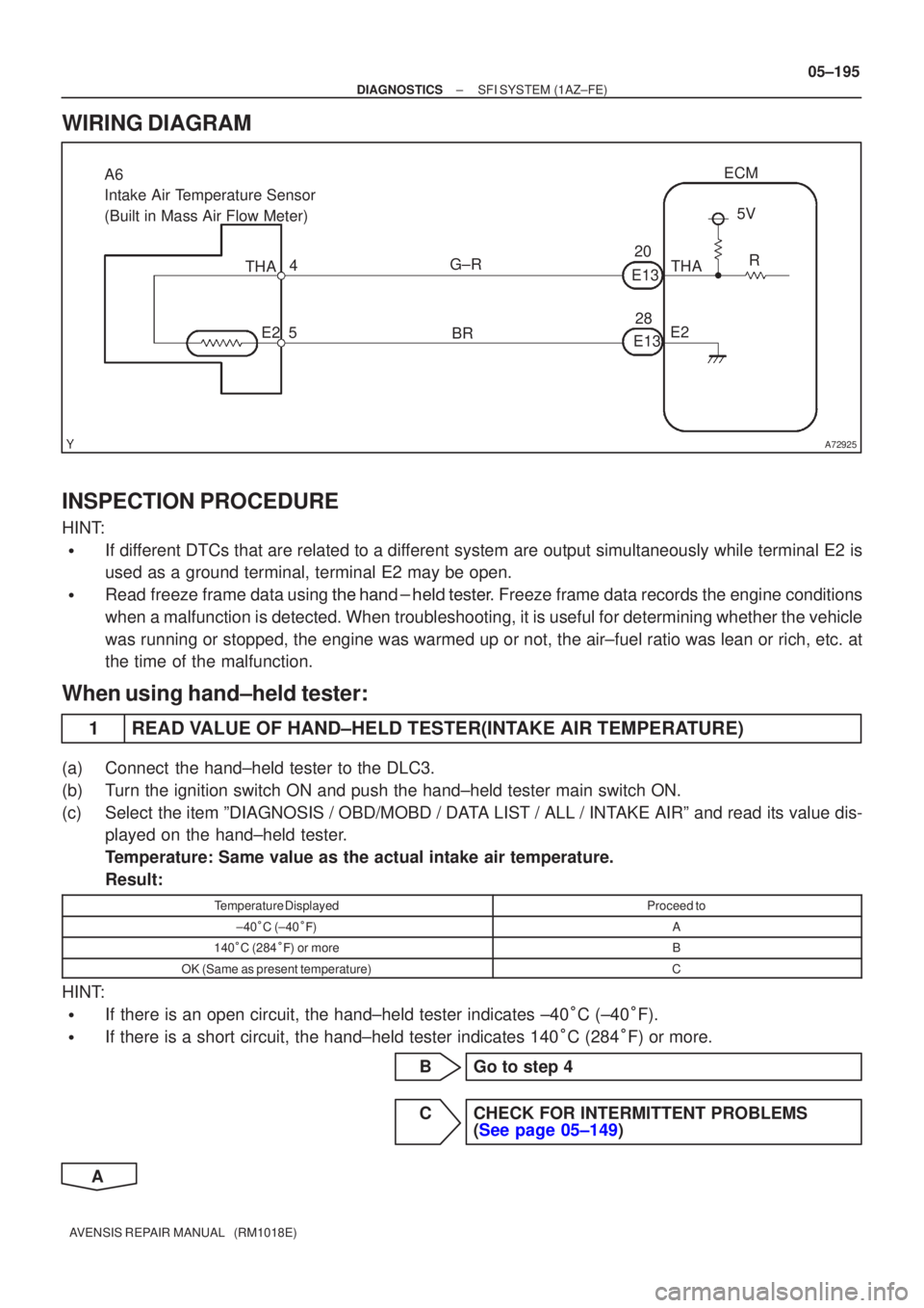
WIRING DIAGRAM
INSPECTION PROCEDURE
HINT:
�If different DTCs that are related to a different system are output simultaneously while terminal E2 is
used as a ground terminal, terminal E2 may be open.
�Read freeze frame data using
\b�\b�
��\b� �
�\f
��� Freeze frame data records the engine conditions
when a malfunction is detected. When troubleshooting, it is useful for d\
etermining whether the vehicle
was running or stopped, the engine was warmed up or not, the air±fuel ra\
tio was lean or rich, etc. at
the time of the malfunction.
When using hand±held tester:
1READ VALUE OF HAND±HELD TESTER(INTAKE AIR TEMPERATURE)
(a)Connect the hand±held tester to the DLC3.
(b)Turn the ignition switch ON and push the hand±held tester main switch \
ON.
(c)Select the item ºDIAGNOSIS / OBD/MOBD / DATA LIST / ALL / INTAKE AIRº and read its value dis- played on the hand±held tester.
Temperature: Same value as the actual intake air temperature.
Result:
Temperature DisplayedProceed to
±40�C (±40 ��)A
140 �C (284 ��) or moreB
OK (Same as present temperature)C
HINT:
�If there is an open circuit, the hand±held tester indicates ±40 �C (±40 �F).
�If there is a short circuit, the hand±held tester indicates 140 �C (284 �F) or more.
BGo to step 4
CCHECK FOR INTERMITTENT PROBLEMS (See page 05±149)
A
Page 353 of 5135
A76863
B±Y
Battery FL MAINEngine Room R/B No. 4
G EFI Relay
A6
Mass Air Flow MeterMREL
B±G 4B 1
W±BB±W 53
2
1
32
E128
E9ECM
EFI No. 1
EC 4A 1
Engine Room
J/B No. 4 1A 1
B±G 1 2
EFI 1
Engine Room
R/B No. 1 and
Engine Room
J/B No.14
4
44
4
4
2
1 W±B
B±R
B±RGR
GRIE1 2
EVG 24
E12VG
L±Y 1
3
2 EA112
± DIAGNOSTICSSFI SYSTEM (1AZ±FE)
05±187
AVENSIS REPAIR MANUAL (RM1018E)
WIRING DIAGRAM
INSPECTION PROCEDURE
HINT:
Read freeze frame data using the hand±held tester. Freeze frame data records the engine conditions when
a malfunction is detected. When troubleshooting, it is useful for determining whether the vehicle was running
or stopped, the engine was warmed up or not, the air±fuel ratio was lean or rich, etc. at the time of the mal-
function.