Page 1090 of 5135

(b) Clearing the DTCs using the SST check wire.
SST 09843±18040
(1) Using SST, connec")
C52361
DLC3:
CGTs 05±1046
± DIAGNOSTICSELECTRONIC MOTOR POWER STEERING SYSTEM
AVENSIS REPAIR MANUAL (RM1018E)
(b) Clearing the DTCs using the SST check wire.
SST 09843±18040
(1) Using SST, connect terminals Ts and CG of the
DLC3.
(2) Turn the ignition switch to ON.
(3) Disconnect and connect the SST check wire from
the CG terminal 4 times or more in 8 seconds end-
ing with it connected.
(4) Check that the P/S warning light blinks a normal
code.
(5) Turn the ignition switch to OFF.
(6) Remove the SST from the DLC3.
SST 09843±18040
3. DTC CHECK (USING HAND±HELD TESTER)
(a) Checking DTCs using the hand±held tester.
(1) Connect the hand±held tester to the DLC3.
(2) Turn the ignition switch to ON.
(3) Read the DTCs by following the prompts on the tes-
ter screen.
HINT:
Refer to the hand±held tester operator's manual for further de-
tails.
(b) Clearing the DTCs using the hand±held tester.
(1) Connect the hand±held tester to the DLC3.
(2) Turn the ignition switch to ON.
(3) Clear the DTCs by following the prompts on the tes-
ter screen.
HINT:
Refer to the hand±held tester operator's manual for further de-
tails.
4. DATA LIST AND FREEZE FRAME DATA
HINT:
Ignition switch must be turned ON, and the vehicle should be placed on a leveled ground to observe data
by using a hand±held tester.
Data List (*: with freeze frame data):
ItemMeasurement Item / Range (Dis-
play)Normal ConditionDiagnostic Note
TRQ1 (*)
Show the output states in the
torque sensor /
Min.: 0 V, Max.: 5 V
Steering wheel center position:
2.3 to 2.7 V
Steering wheel right turned:
2.5 to 4.7 V
Steering wheel left turned:
0.3 to 2.5 V
±
TRQ2 (*)
Show the output states in the
torque sensor /
Min.: 0 V, Max.: 5 V
Steering wheel center position:
2.3 to 2.7 V
Steering wheel right turned:
2.5 to 4.7 V
Steering wheel left turned:
0.3 to 2.5 V
±
Page 1091 of 5135
ItemDiagnostic Note Normal Condition Measurement Item / Range (Dis-
play)
TRQ3 (*)
Show the output states")
± DIAGNOSTICSELECTRONIC MOTOR POWER STEERING SYSTEM
05±1047
AVENSIS REPAIR MANUAL (RM1018E)ItemDiagnostic Note Normal Condition Measurement Item / Range (Dis-
play)
TRQ3 (*)
Show the output states in the
torque sensor /
Min.: 0 V, Max.: 5 V
Steering wheel center position:
2.3 to 2.7 V
Steering wheel right turned:
2.5 to 4.7 V
Steering wheel left turned:
0.3 to 2.5 V
±
SPD (*)
Show the vehicle speed on the
speedometer /
Min.: 0 km/h (0 mph),
Max.: 255 km/h (158 mph)
Actual vehicle speedVehicle speed indicated on
speedometer
ENGINE REV (*)
Show the engine revolution /
Min.: 0 rpm
Max.: 8,192 rpm
Actual engine speed±
MOTOR ACTUAL (*)Show the current flowing motor /
Min.: ±128 A, Max.: 128 A0 to 65 A±
COMMAND VALUE (*)Show the specified current value /
Min.: ±128 A, Max.: 128 A0 to 65 A±
THERMISTOR TEMP (*)
Show the temperature of the
thermistor /
Min.: ±50 �C, Max.: 205 �C
±±
PIG SUPPLY (*)
Show the power supply voltage for
driving motor /
Min.: 0 V, Max.: 25 V
10 to 16 VWhile power steering operated
IG SUPPLY (*)Show the power supply condition /
Min.: 0 V, Max.: 25 V10 to 16 V±
TRQ1 ZERO VAL (*)Show the torque sensor/
Min.: 0 V, Max.: 5 VSteering wheel center position:
2.3 to 2.7 V±
TRQ2 ZERO VAL (*)Show the torque sensor/
Min.: 0 V, Max.: 5 VSteering wheel center position:
2.3 to 2.7 V±
TRQ3 ZERO VAL (*)Show the torque sensor/
Min.: 0 V, Max.: 5 VSteering wheel center position:
2.3 to 2.7 V±
MTR OVERHEAT
Record of continuous overheat
preventive control /
record or un±record
Un±record±
MTR LOW POWERRecord of low motor power supply
voltage / record or un±recordUn±record±
MTR HIGH POWERRecord of high motor power sup-
ply voltage / record or un±recordUn±record
#CODESNumber of DTC recorded /
Min.: 0, Max.: 255Min.: 0, Max.: XX±
ASSIST MAPShow the selected condition of the
assist map / 01, 02, 03, 11 or 12±±
ECU IDShow the identified information of
ECU / 01, 02, 03, 04 or 05±±
TEST MODE STATTest mode status / NORMAL or
TESTNORMAL: Normal mode
TEST: During test mode±
Page 1093 of 5135

6.INPUT SIGNAL CHECK (TEST MODE)
(USING HAND±HELD TESTER)
(a)Check the input sign")
C52361
DLC3:CGTs
Tc
±
DIAGNOSTICS ELECTRONIC MOTOR POWER STEERING SYSTEM
05±1049
AVENSIS REPAIR MANUAL (RM1018E)
6.INPUT SIGNAL CHECK (TEST MODE)
(USING HAND±HELD TESTER)
(a)Check the input signal using the hand±held tester.
(1)Connect the hand±held tester to the DLC3.
(2)Check that the warning light goes off with driving thevehicle more than 10 km/h (6 mph) and engine
speed more than 300 rpm.
(3)Read the DTC by following the prompts on the tes- ter screen.
HINT:
�Refer to the hand±held tester operator's manual for fur-
ther details.
�See the list of DTC shown in the table below.
�Even if a sensor is normal, it outputs codes C1571/71 and
C1573/73 during test mode.
DTC of input signal check function:
Code No.
(See page)DiagnosisTrouble Area
C1571/71
(05±1067)Speed sensor signal check 1 (Test mode)
� Speed sensor
� Speed sensor circuit
� Skid control ECU assy
� Combination meter assy
� Power steering ECU assy
C1573/73
(05±1070)Engine revolution signal check (Test mode)
� Engine revolution signal circuit
� ECM
� Power steering ECU assy
7. CALIBRATION OF TORQUE SENSOR ZERO POINT
(USING SST CHECK WIRE)
HINT:
Perform this operation in the following cases.
�When removing and installing ºsteering wheel assemblyº,
ºtilt steering column assemblyº and ºsteering gear assem-
blyº.
�When replacing power steering ECU assy.
(a) Place front wheels and steering wheel facing straight ahead.
(b) Perform the torque sensor zero point initialization.
HINT:
If the power steering ECU assy is replaced, initialization is not
necessary. (1) Stop the vehicle and turn the ignition switch OFF.
(2) Using SST, connect terminals Ts and CG of DLC3.
SST 09843±18040
(3) Using SST, connect terminals Tc and CG of DLC3.
SST 09843±18040
(4) Turn the ignition switch ON.
Page 1094 of 5135

(5) Disconnect and connect the terminal Tc of DLC3 20
times within 20 seconds.
(6) Che")
C52361
DLC3:
CGTs 05±1050
± DIAGNOSTICSELECTRONIC MOTOR POWER STEERING SYSTEM
AVENSIS REPAIR MANUAL (RM1018E)
(5) Disconnect and connect the terminal Tc of DLC3 20
times within 20 seconds.
(6) Check the DTC C1515/15 output.
(c) Perform the torque sensor zero point calibration.
HINT:
�Do not touch the steering wheel.
�Check that the DTC for except C1515/15 is not output.
(1) Stop the vehicle and turn the ignition switch to OFF.
(2) Using SST, connect terminals Ts and CG of DLC3
and turn the ignition switch to ON.
SST 09843±18040
(3) Disconnect the SST.
SST 09843±18040
(4) Check the DTC is not output.
8. CALIBRATION OF TORQUE SENSOR ZERO POINT
(USING HAND±HELD TESTER)
HINT:
Perform this operation in the following cases.
�When removing and installing ºsteering wheel assemblyº,
ºtilt steering column assemblyº and ºsteering gear assem-
blyº.
�When replacing power steering ECU assy.
(a) Place front wheels and steering wheel facing straight
ahead.
(b) Perform the torque sensor zero point initialization.
HINT:
If the power steering ECU assy is replaced, initialization is not
necessary.
(1) Stop the vehicle.
(2) Connect the hand±held tester to the DLC3.
(3) Select the ºTRQ SENS ADJUSTº mode on the
hand±held tester.
(4) Select the ºZERO POINT INITIALIZEº.
(5) Following the screen instructions, perform the
torque sensor zero point initialization.
(c) Perform the torque sensor zero point calibration.
HINT:
Do not touch the steering wheel.
(1) Connect the hand±held tester to the DLC3.
(2) Turn the ignition switch ON.
(3) Select the ºTRQ SENS ADJUSTº mode on the
hand±held tester.
(4) Select the ºZERO POINT ADJUSTº.
(5) Following the screen instructions, perform the
torque sensor zero point calibration.
Page 1097 of 5135
± DIAGNOSTICSELECTRONIC MOTOR POWER STEERING SYSTEM
05±1053
AVENSIS REPAIR MANUAL (RM1018E)
(4) Align the marks on the torque sensor wire harness
with the clamp, as shown in the illustration.
NOTICE:
�When reusing the clamp, check that there is no dam-
age on it.
�When reinstalling the wire harness, make sure there
is no twist in the harness or with other wire harness.
10. FAIL SAFE FUNCTION
(a) If the power steering ECU assy detects a trouble, the ECU
assy halt, fix or lower the steering power assist in order to
protect the system.
HINT:
Repeating the steering operation when stopping or driving at
low speed, or leaving the steering wheel turn fully for long hours
will lower the amount of power assist in order to prevent power
steering ECU assy from heating up. In this case, not operating
the steering for about 10 minutes with engine idle will lead the
fail safe function to return the normal state.
Page 1916 of 5135

11±75
AVENSIS REPAIR MANUAL (RM1018E)
52.INSTALL TIMING BELT GUIDE(See page 14±307)
53.INSTALL TIMING BELT NO.1 COVER(See page 14±307)
54.INSTALL")
±
FUEL INJECTION OR SUPPLY PUMP ASSY (1CD±FTV)
11±75
AVENSIS REPAIR MANUAL (RM1018E)
52.INSTALL TIMING BELT GUIDE(See page 14±307)
53.INSTALL TIMING BELT NO.1 COVER(See page 14±307)
54.INSTALL TIMING BELT NO.2 COVER(See page 14±307)
55. INSTALL IDLER PULLEY SUB±ASSY
Torque: 40 N �m (408 kgf �cm, 30 ft �lbf)
56.INSTALL CRANKSHAFT PULLEY(See page 14±307) SST 09213±54015 (90105±08076), 09330±00021
57.INSTALL ENGINE MOUNTING INSULATOR SUB±ASSY RH(See page 14±307)
58. INSTALL INJECTOR DRIVER Torque: 5.0 N �m (51 kgf �cm, 44 in. �lbf)
59. ADJUST V (COOLER COMPRESSOR TO CRANKSHAFT PULLEY) BELT NO.1 (See page 14±269)
60.INSTALL RADIATOR RESERVE TANK ASSY(See page 16±50)
61. INSTALL ENGINE COVER NO.1 Torque: 8.0 N �m (82 kgf �cm, 71 in. �lbf)
62.INSTALL AIR CLEANER ASSY (See page 11±60)
63. INSTALL FRONT WHEEL RH
Torque: 103 N �m (1,050 kgf �cm, 76 ft �lbf)
64.ADD ENGINE COOLANT(See page 16±44)
65.CHECK FOR ENGINE COOLANT LEAKS(See page 16±37)
66.CHECK FOR FUEL LEAKS(See page 11±60)
Page 2038 of 5135
A79324
A78459
±
ENGINE MECHANICAL CHAIN SUB±ASSY(1ZZ±FE/3ZZ±FE)
14±59
AVENSIS REPAIR MANUAL (RM1018E)
43.INSTALL V±RIBBED IDLER ASSY NO.1
(a)Install the tube and idler with the nut and bolt.
Torque: 39.2 N �m (400 kgf �cm, 29 ft �lbf)
44.INSTALL CYLINDER HEAD COVER NO.2
(a)Install the cylinder head cover with the 2 nuts and 2 clips. Torque: 7.0 N �m (71 kgf �cm, 62 in. �lbf)
45.INSTALL FRONT WHEEL RH Torque: 103 N �m (1,050 kgf �cm, 76 ft �lbf)
46.ADD ENGINE COOLANT(See page 16±7)
47.CHECK FOR ENGINE COOLANT LEAKS(See page 16±7)
48. CHECK FOR ENGINE OIL LEAKS
Page 2057 of 5135
A76713
A62838SST
A62205
1
5
3
82
6
4
7
A62206
90�
A62838SST
± ENGINE MECHANICALPARTIAL ENGINE ASSY (1ZZ±FE/3ZZ±FE)
14±41
AVENSIS REPAIR MANUAL (RM1018E)
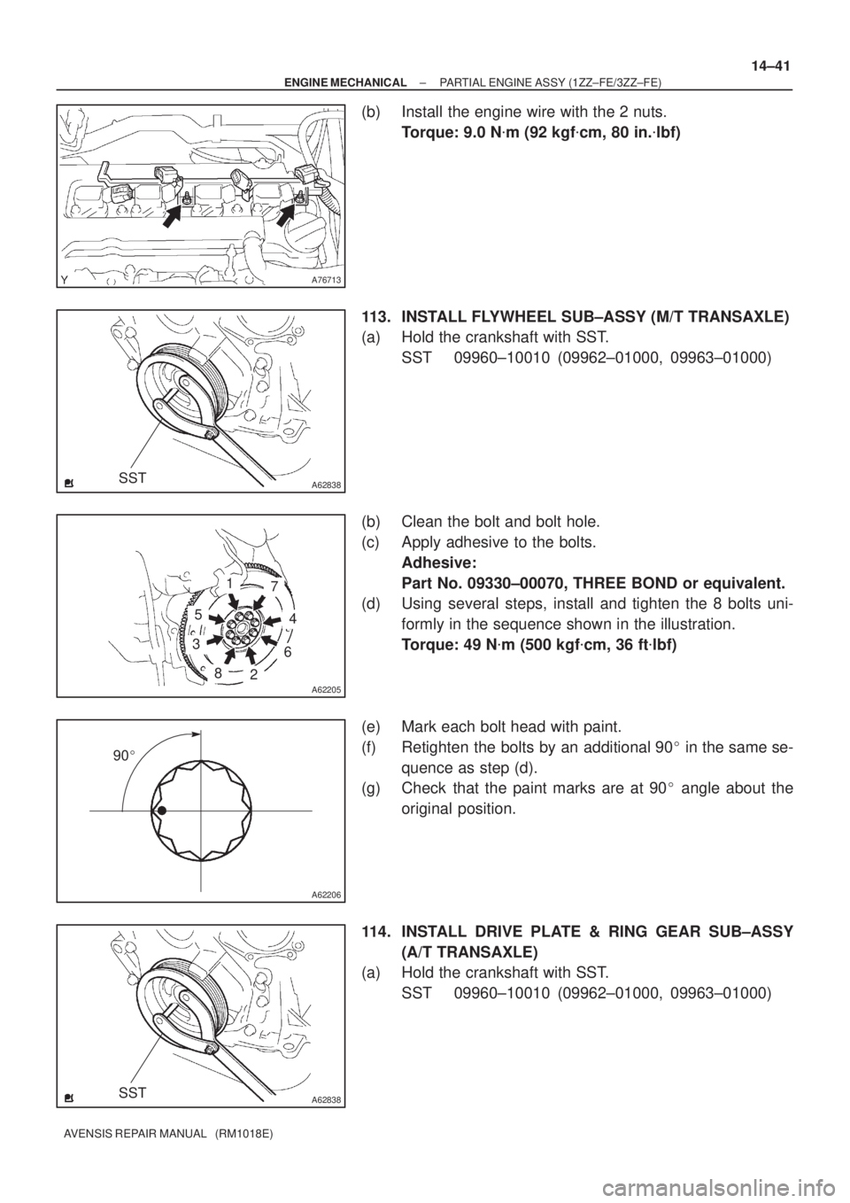
(b) Install the engine wire with the 2 nuts.
Torque: 9.0 N�m (92 kgf�cm, 80 in.�lbf)
113. INSTALL FLYWHEEL SUB±ASSY (M/T TRANSAXLE)
(a) Hold the crankshaft with SST.
SST 09960±10010 (09962±01000, 09963±01000)
(b) Clean the bolt and bolt hole.
(c) Apply adhesive to the bolts.
Adhesive:
Part No. 09330±00070, THREE BOND or equivalent.
(d) Using several steps, install and tighten the 8 bolts uni-
formly in the sequence shown in the illustration.
Torque: 49 N�m (500 kgf�cm, 36 ft�lbf)
(e) Mark each bolt head with paint.
(f) Retighten the bolts by an additional 90� in the same se-
quence as step (d).
(g) Check that the paint marks are at 90� angle about the
original position.
114. INSTALL DRIVE PLATE & RING GEAR SUB±ASSY
(A/T TRANSAXLE)
(a) Hold the crankshaft with SST.
SST 09960±10010 (09962±01000, 09963±01000)

(4) Align the marks on the torque sensor wire harness
with the clamp, as shown in the illustration.
NOTI")

14±59
AVENSIS REPAIR MANUAL (RM1018E)
43.INSTALL V±RIBBED IDLER ASSY NO.1
(a)Install the tube and idler with the nut and bolt.
T")