Page 1912 of 5135
A79150
A79151
A79152
A62166
SST
±
FUEL INJECTION OR SUPPLY PUMP ASSY(1CD±FTV)
11±71
AVENSIS REPAIR MANUAL (RM1018E)
29.REMOVE INTAKE MANIFOLD INSULATOR NO.1
(a)Remove the 2 bolts and the intake manifold insulator.
30.REMOVE OIL LEVEL GAGE SUB±ASSY
31.REMOVE OIL LEVEL GAGE GUIDE(See page 17±22)
32.REMOVE WATER INLET(See page 16±50) 33. DISCONNECT INJECTION PUMP TO FUEL PIPE FUELHOSE
(a) Disconnect the injection pump to fuel pipe fuel hose from the supply pump.
34. DISCONNECT INJECTION PUMP TO FUEL FILTER FUEL HOSE OR PIPE
(a) Disconnect the injection pump to fuel filter fuel hose or pipe from the supply pump.
35. REMOVE INJECTION PUMP DRIVE PULLEY
(a) Using SST, remove the pulley nut. SST 09960±10010 (09962±01000, 09963±01000)
Page 1913 of 5135

AVENSIS REPAIR MANUAL (RM1018E)
(b)Using SST, remove the injection pump drive pulley. SST09950±50013 (09951±05010")
A62779SST
A79153
A62166
SST
11±72
±
FUEL INJECTION OR SUPPLY PUMP ASSY(1CD±FTV)
AVENSIS REPAIR MANUAL (RM1018E)
(b)Using SST, remove the injection pump drive pulley. SST09950±50013 (09951±05010, 09952±05010, 09953±05020, 09954±05021)
36.REMOVE INJECTION OR SUPPLY PUMP ASSY
(a)Remove the 2 nuts and the injection pump.
37.INSTALL INJECTION OR SUPPLY PUMP ASSY Torque: 21 N �m (210 kgf �cm, 15 ft �lbf)
38.INSTALL INJECTION PUMP DRIVE PULLEY
(a)Using SST, install the pulley nut. SST09960±10010 (09962±01000, 09963±01000)
Torque: 64 N �m (650 kgf �cm, 47 ft �lbf)
39.INSTALL WATER INLET(See page 16±50)
40.INSTALL OIL LEVEL GAGE GUIDE(See page 17±22)
41. INSTALL INTAKE MANIFOLD INSULATOR NO.1 Torque: 5.0 N �m (51 kgf �cm, 44 in. �lbf)
42. INSTALL INJECTION PIPE SUB±ASSY NO.1
NOTICE:
When assembling the pipes, perform the operation with the
engine cold under room temperature.
(a) Remove the vinyl or the plastic bag from the injector and vinyl tape from the common rail.
(b) Temporarily install the injection pipe.
Page 1919 of 5135
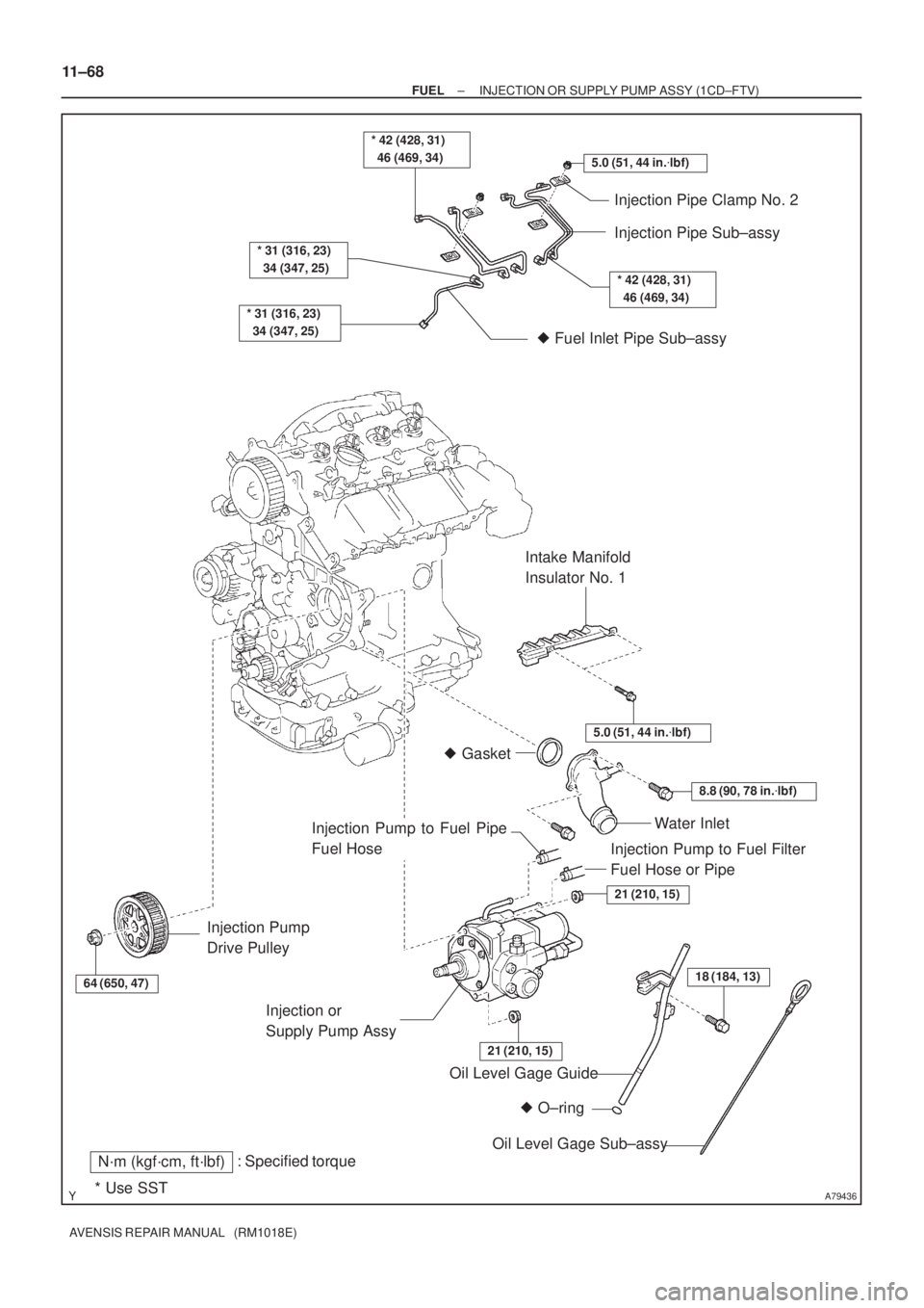
A79436
5.0 (51, 44 in.�lbf)
* 42 (428, 31)
46 (469, 34)
* 31 (316, 23)
34 (347, 25)
* 31 (316, 23)
34 (347, 25)
Injection Pipe Clamp No. 2
Injection Pipe Sub±assy
� Fuel Inlet Pipe Sub±assy
64 (650, 47)
Injection Pump
Drive Pulley
� O±ring Oil Level Gage Guide
: Specified torqueN´m (kgf´cm, ft´lbf)
* Use SST
18 (184, 13)
Oil Level Gage Sub±assy Injection or
Supply Pump Assy
21 (210, 15)
21 (210, 15)
Water Inlet
8.8 (90, 78 in.�lbf)
� Gasket
5.0 (51, 44 in.�lbf)
Intake Manifold
Insulator No. 1
* 42 (428, 31)
46 (469, 34)
Injection Pump to Fuel Filter
Fuel Hose or Pipe
Injection Pump to Fuel Pipe
Fuel Hose
11±68
± FUELINJECTION OR SUPPLY PUMP ASSY (1CD±FTV)
AVENSIS REPAIR MANUAL (RM1018E)
Page 2030 of 5135

14±51
AVENSIS REPAIR MANUAL (RM1018E)
15.REMOVE CYLINDER")
A64856
A62185
MarkMark
Mark Timing Chain
Cover Surface
Timing
Notch
A62837SST
A11858
±
ENGINE MECHANICAL CHAIN SUB±ASSY(1ZZ±FE/3ZZ±FE)
14±51
AVENSIS REPAIR MANUAL (RM1018E)
15.REMOVE CYLINDER HEAD COVER SUB±ASSY
(a)Remove the 9 bolts, 2 seal washers, 2 nuts and 3 clamp
brackets and detach the cylinder head cover.
16.SET NO. 1 CYLINDER TO TDC/COMPRESSION
(a)Turn the crankshaft pulley to align the timing notch with timing mark º0º of the timing chain cover.
(b)Check that the point marks of the camshaft timing sprock- et and VVT timing sprocket are in straight line on the tim-
ing chain cover surface as shown in the illustration.
HINT:
If not, turn the crankshaft 1 revolution (360 �) and align the
marks as above.
17.REMOVE CRANKSHAFT PULLEY
(a)Using SST, remove the pulley bolt. SST09960±10010 (09962±01000, 09963±01000)
(b)Remove the crankshaft pulley from the crankshaft.
18.REMOVE V±RIBBED BELT TENSIONER ASSY
(a)Remove the bolt and nut and detach V±ribbed belt ten- sioner.
HINT:
Jack up and down to remove the bolt.
19.REMOVE WATER PUMP ASSY(See page 16±9)
Page 2034 of 5135
3 (0.118)
A
ABB
C
C
7 (0.276)
4.5 (0.177)
12 (0.472)6 (0.236)
3 (0.118)
Width 4 (0.157)
A ± AB ± B
C ± C
08826±00100 or equivalent
08826±00080 or equivale")
A65676
Timing Chain Cover side:
3 (0.118)3 (0.118)
A
ABB
C
C
7 (0.276)
4.5 (0.177)
12 (0.472)6 (0.236)
3 (0.118)
Width 4 (0.157)
A ± AB ± B
C ± C
08826±00100 or equivalent
08826±00080 or equivalent
(mm (in.))
A65677
A
A
AA
A
A
AAA B
B
B
± ENGINE MECHANICALCHAIN SUB±ASSY (1ZZ±FE/3ZZ±FE)
14±55
AVENSIS REPAIR MANUAL (RM1018E)
(b) Apply a continuous bead of seal packing (Diameter 3.5
mm to 4.5 mm (0.1379 to 0.177 in.)) as shown in the il-
lustration.
Seal packing:
Water pump part part No. 08826±00100 or equivalent
Other part part No. 08826±00080 or equivalent.
NOTICE:
�Remove any oil from the contact surface.
�Install the oil pan within 3 minutes after applying seal
packing.
�Do not expose the seal to engine oil within 2 hours af-
ter installing.
(c) Install the timing chain cover with the 11 bolts and nut.
Torque:
13 N�m (133 kgf�cm, 10 ft�lbf) for A
19 N�m (194 kgf�cm, 14 ft�lbf) for B
(d) Using a torx wrench socket (E8), install the stud bolt.
Torque: 9.5 N�m (97 kgf�cm, 84 in.�lbf)
Page 2035 of 5135

AVENSIS REPAIR MANUAL (RM1018E)
33.INSTALL CHAIN TENSIONER ASSY NO.1
(a)Check")
A62177
Raise
Push
Hook
Pin
A62178
Push
A76692
A12816
A11858
14±56
±
ENGINE MECHANICAL CHAIN SUB±ASSY(1ZZ±FE/3ZZ±FE)
AVENSIS REPAIR MANUAL (RM1018E)
33.INSTALL CHAIN TENSIONER ASSY NO.1
(a)Check that the O±ring is clean, and set the hook as shown in the illustration.
(b)Apply engine oil to the chain tensioner and install it with the 2 nuts.
Torque: 9.0 N �m (92 kgf �cm, 80 in. �lbf)
NOTICE:
If the hook released the plunger during installation, re±
hook the plunger by the hook to fix it.
34.INSTALL CRANKSHAFT POSITION SENSOR
(a)Apply a coat of the engine oil to the O±ring of the crank- shaft position sensor.
(b)Install the crankshaft position sensor with the 2 bolts. Torque: 9.0 N �m (92 kgf �cm, 80 in. �lbf)
35.INSTALL TRANSVERSE ENGINE ENGINE MOUNTING BRACKET
(a)Install the transverse engine engine mounting bracket with the 3 bolts.
Torque: 47 N �m (479 kgf �cm, 35 ft �lbf)
36.INSTALL WATER PUMP ASSY(See page 16±9)
37. INSTALL V±RIBBED BELT TENSIONER ASSY
(a) Install the V±ribbed belt tensioner with the nut and bolt. Torque:
29 N�m (296 kgf �cm, 21 ft �lbf) for Nut
69 N �m (704 kgf �cm, 51 ft �lbf) for Bolt
Page 2042 of 5135
A60625
Crankshaft Pulley V±ribbed Belt
Tensioner Assy
Water Pump AssyTransverse Engine
Engine Mounting Bracket
Crankshaft Position Sensor Chain Tensioner Assy No. 1
Timing Chain or
Belt Cover Sub±assy
� Oil Seal
Crankshaft Position Sensor
Plate No. 1Chain Sub±assy
Chain Tensioner Slipper
Crankshaft timing Sprocket� O±ring
� Non±reusable part
N´m (kgf´cm, ft´lbf) : Specified torque
47 (479, 35)
29 (296, 21)
69 (704, 51)
138 (1,047, 102)
13 (133, 10)
9.0 (92, 80 in.�lbf)
9.0 (92, 80 in.�lbf)
19 (194, 14)
9.0 (92, 80 in.�lbf) (L=20)
11 (112, 8) (L=35)
9.5 (97, 84 in.�lbf)
13 (133, 10) (M6)
19 (194, 14) (M8)
14±48
± ENGINE MECHANICALCHAIN SUB±ASSY (1ZZ±FE/3ZZ±FE)
AVENSIS REPAIR MANUAL (RM1018E)
Page 2112 of 5135

14±85
AVENSIS REPAIR MANUAL (RM1018E)
33.REMOVE CYL")
A64856
A62185
MarkMark
Mark Timing Chain
Cover Surface
Timing
Notch
A62837SST
A11858
±
ENGINE MECHANICAL CYLINDER HEAD GASKET(1ZZ±FE/3ZZ±FE)
14±85
AVENSIS REPAIR MANUAL (RM1018E)
33.REMOVE CYLINDER HEAD COVER SUB±ASSY
(a)Remove the 9 bolts, 2 seal washers, 2 nuts and 3 clamp
brackets.
(b)Remove the cylinder head cover.
34.SET NO. 1 CYLINDER TO TDC/COMPRESSION
(a)Turn the crankshaft pulley to align the timing notch with the timing mark º0º of the timing chain cover.
(b)Check that the point marks of the camshaft timing sprock- et and VVT timing sprocket are in straight line on the tim-
ing chain cover surface as shown in the illustration.
HINT:
If not, turn the crankshaft 1 revolution (360 �) and align the
marks as above.
35.REMOVE CRANKSHAFT PULLEY
(a)Using SST, remove the pulley bolt. SST09960±10010 (09962±01000, 09963±01000)
(b)Remove the crankshaft pulley from the crankshaft.
36.REMOVE V±RIBBED BELT TENSIONER ASSY
(a)Remove the bolt and nut and detach the V±ribbed belt tensioner.
HINT:
Jack up and down to remove the bolt.
37.REMOVE WATER PUMP ASSY(See page 16±9)

11±71
AVENSIS REPAIR MANUAL (RM1018E)
29.REMOVE INTAKE MANIFOLD INSULATOR NO.1
(a)Remove the 2 bolts and the intake m")