Page 2796 of 5135

410DS±01
D30478
Battery Clamp Sub±assy
Battery Tray
Charcoal Canister Assy Battery Carrier
Transmission Control Cable AssyClipAir Cleaner Assy
Hood Sub±assy
Cylinder Head Cover No.2
Starter AssyBack±up Lamp
SwitchConnector
Transverse Engine
Engine Mounting Bracket
Clip
Clip
ClipClip
37 (380, 27)
Starter Connector
Transverse Engine
Engine Mounting Insulator
52 (530, 38)
52 (530, 38)
Ground Cable � Gasket
7.0 (71, 62 in.�lbf)
Filler Plug
37 (380, 27)
23 (230, 17)
47 (479, 35)
N´m (kgf´cm, ft´lbf) : Specified torque
19 (195, 14)
13 (130, 9)
64 (653, 47)
64 (653, 47)
5.0 (51, 44 in.�lbf)
� Non±reusable part
5.0 (51, 44 in.�lbf)
14 (141, 10)
13 (133, 10)
13 (131, 9)
5.0 (51, 44 in.�lbf)
26 (260, 19)
25 (255, 18)
80 (816, 59)
26 (260, 19)
23 (230, 17)
Engine Room Cover Side
Radiator Support Opening Cover
40 (410, 30)
39 (400, 29)
Manual Transaxle Assy
64 (653, 47)
Battery
Clutch Release Cylinder Assy
± MANUAL TRANSMISSION/TRANSAXLEMANUAL TRANSAXLE ASSY (1ZZ±FE/3ZZ±FE)
41±13
AVENSIS REPAIR MANUAL (RM1018E)
MANUAL TRANSAXLE ASSY (1ZZ±FE/3ZZ±FE)
COMPONENTS
Page 2908 of 5135

I37057
0.1 (1.0)0.4 (4.0)
0.3 (3.0)
0.2 (2.0)MPa (kgf/cm
2) Pressure on low pressure side
Outside temperature 0
�C (�F) 15 (59) 20 (68) 30 (86)25 (77) 35 (95)
0 g (0 oz.)
(Standa")
± 50 g (± 1.76 oz.)
I37057
0.1 (1.0)0.4 (4.0)
0.3 (3.0)
0.2 (2.0)MPa (kgf/cm
2) Pressure on low pressure side
Outside temperature 0
�C (�F) 15 (59) 20 (68) 30 (86)25 (77) 35 (95)
0 g (0 oz.)
(Standard)
+ 50 g (+ 1.76 oz.)
± HEATER & AIR CONDITIONERREFRIGERANT
55±31
AVENSIS REPAIR MANUAL (RM1018E)
3. w/ Hot gas heater:
INSPECT REFRIGERANT VOLUME
(a) This is a method to specify the trouble area by using a
manifold gauge set. Read the the manifold gauge pres-
sure when these conditions are established.
Test conditions:
�Engine is at idle.
�Blower speed control switch is at ºHIº.
�Temperature control dial is at ºMAX. COOLº.
�Engine has been warmed up.
�All doors are fully open.
�Hood is fully open.
�Air inlet mode selector damper is at RECIRE.
�Air outlet damper is at FACE.
�Outside temperature is 15 ± 35 �C (59± 95
�F).
(b) Check refrigerant volume according to the graph below.
RangeAmount of refrigerantCorrective actions
Except range belowInsufficient or excessive
Supply refrigerant until low
pressure become within
the standard �50 g
(�1.76 oz.), or remove
refrigerant and then sup-
ply proper amount of re-
frigerant
Standard �50 g
(�1.76 oz.)Proper±
Page 3000 of 5135

5. REMOVE DISCHARGE TUBE SUB±ASSY (W/ HOT GAS HEATER)
(a) Remove the 2 bolts")
I35337
I35336
I35339
I35340
55±94
±
HEATER & AIR CONDITIONER W/RECEIVER CONDENSER ASSY
AVENSIS REPAIR MANUAL (RM1018E)
5. REMOVE DISCHARGE TUBE SUB±ASSY (W/ HOT GAS HEATER)
(a) Remove the 2 bolts and disconnect the discharge tube
sub±assy from the w/ receiver condenser assy.
(b) Remove 2 O±rings from the discharge tube sub±assy.
NOTICE:
Seal the opening of the disconnected parts using vinyl tape
to prevent moisture and foreign matters from entering.
6. REMOVE LIQUID TUBE SUB±ASSY B (RHD(1CD±FTV) STEERING POSITION TYPE)
(a) Remove the bolt and disconnect the liquid tube sub±assy B from w/ receiver condenser assy.
(b) Remove the O±ring from the liquid tube sub±assy B.
NOTICE:
Seal the opening of the disconnected parts using vinyl tape
to prevent moisture and foreign matters from entering.
7. REMOVE HOOD LOCK ASSY
(a) Remove the 3 bolts and the hood lock assy.
8.REMOVE HIGH PITCHED HORN ASSY (See page 69±5)
9.REMOVE LOW PITCHED HORN ASSY (See page 69±4) 10. REMOVE HOOD LOCK SUPPORT BRACE
(a) Remove the 5 bolts and the hood lock support brace.
Page 3228 of 5135
B660325 Clips
or
oror
or
or
or
71±18
±
INSTRUMENT PANEL/METER INSTRUMENT PANEL SUB±ASSY LOWER
AVENSIS REPAIR MANUAL (RM1018E)
36.REMOVE INSTRUMENT PANEL LOWER ASSY
(a)Disconnect the hood lock control cable.
(b)Using a clip remover, remove the 2 clips.
(c)Remove the 2 bolts 7 screws or .
(d)Disengage the wire harness 5 clamps.
(e)Remove the instrument panel lower assy.
37.REMOVE OUTER MIRROR SWITCH ASSY W/BEZEL
38.REMOVE FUSE BOX OPENING COVER
39.REMOVE GLOVE BOX LAMP ASSY
40.REMOVE INSTRUMENT PANEL BRACKET SUB±ASSY CENTER
(a)Remove the screw and the instrument panel bracket sub±assy center.
41.REMOVE INSTRUMENT PANEL SUB±ASSY LOWER
42.INSTALL INSTRUMENT PANEL AIR BAG ASSY (See page 60±29)
Page 3299 of 5135

THEFT DETERRENT SYSTEM
ON±VEHICLE INSPECTION
1. OUTLINE OF THEFT DETERRENT SYSTEM
(a) When the")
730G8±01
± THEFT DETERRENT & DOOR LOCKTHEFT DETERRENT SYSTEM
73±31
AVENSIS REPAIR MANUAL (RM1018E)
THEFT DETERRENT SYSTEM
ON±VEHICLE INSPECTION
1. OUTLINE OF THEFT DETERRENT SYSTEM
(a) When the theft deterrent system detects that the vehicle is being tampered with, the system sets off
the alarm, causing the horns to sound and the lights to light up or blink in order to alert people around
the vehicle to the theft.
(b) The theft deterrent system has an active arming mode; a disarmed state, an arming preparation state,
an armed state and an alarm sounding state.
(1) Disarmed state:
�The alarm function is not operating.
�The theft deterrent system is not operating.
(2) Arming preparation state:
�The time until the system goes into the armed state.
�The theft deterrent system is not operating.
(3) Armed state:
�The theft deterrent system is operating.
HINT:
If the vehicle remains in a condition that sets off the alarm (any door remains open, engine hood remains
open, ignition switch remains directly connected) after the alarm ends, the alarm will be set off repeatedly
a maximum of 10 times for every one of the above specified conditions.
Alarm time: Approx. 27.5 sec. x 10
(4) Alarm sounding state:
When the theft deterrent system detects that the vehicle is being tampered with while in the
armed state, the system causes the horns to sound and the lights to light up or blink in order to
alert people around the vehicle to the theft.
Refer to table below for alarm method and time:
Hazard Warning LampBlinking (Cycle of flasher relay)
Alarm MethodRoom LampIlluminatingAlarm MethodVehicle HornSounding (Cycle of 0.4 sec.)
Self±power SirenSounding (Cycle of 0.4 sec.)
Alarm TimeApprox. 27.5 sec. (Maximum 10 times)
HINT:
If any of the doors are unlocked with no key in the ignition key cylinder during the armed state, a forced door
lock signal will be output (See step 3).
Page 3300 of 5135
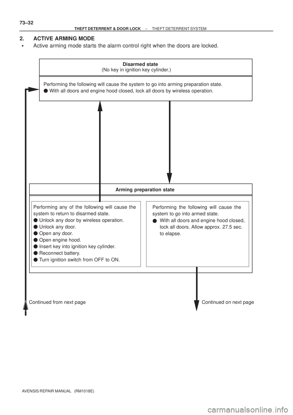
Disarmed state
(No key in ignition key cylinder.)
Continued from next page Continued on next pagePerforming the following will cause the system to go into arming preparation state.
� With all doors and engine hood closed, lock all doors by wireless operation.
Arming preparation state
Performing any of the following will cause the
system to return to disarmed state.
� Unlock any door by wireless operation.
� Unlock any door.
� Open any door.
� Open engine hood.
� Insert key into ignition key cylinder.
� Reconnect battery.
� Turn ignition switch from OFF to ON.With all doors and engine hood closed,
lock all doors. Allow approx. 27.5 sec.
to elapse.
Performing the following will cause the
system to go into armed state.
� 73±32
± THEFT DETERRENT & DOOR LOCKTHEFT DETERRENT SYSTEM
AVENSIS REPAIR MANUAL (RM1018E)
2. ACTIVE ARMING MODE
�Active arming mode starts the alarm control right when the doors are locked.
Page 3301 of 5135

Alarm sounding state
Performing the following will cause the
system to return to disarmed state.When the system detects tam-
pering, horns sound and lights
illuminate or blink in order to
alert people around the vehicle
to the theft.
After approx. 27.5 sec., alarm
stops and system returns to
armed state.
Armed state
Performing any of the following will
cause the system to return to dis-
armed state.Performing any of the follow-
ing will cause the system to
go into alarm sounding state.
Alarm sounding state is canceled.Tampering is detected.
Alarm stops and system
returns to armed state.
Continued from previous page Continued on previous page
�Insert key into ignition key cylin-
der, turn ignition switch ON and
run engine over 550 rpm for 10
to 12 sec.
�Unlock all doors by wireless op-
eration.Directly connect ignition
switch without key (or turn
ignition switch ON without
key). �Open engine hood.
�Reconnect battery.
�Open any door.
�
�Unlock all doors by wireless operation.
± THEFT DETERRENT & DOOR LOCKTHEFT DETERRENT SYSTEM
73±33
AVENSIS REPAIR MANUAL (RM1018E)
Page 3354 of 5135
750MX±01
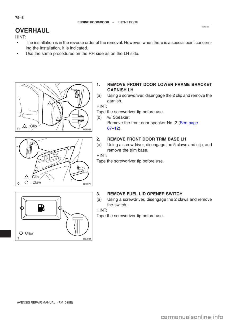
B66969: Clip
B66970
: Clip
: Claw
B67801
Claw
75±8
±
ENGINE HOOD/DOOR FRONT DOOR
AVENSIS REPAIR MANUAL (RM1018E)
OVERHAUL
HINT:
�The installation is in the reverse order of the removal. However, when there is a special point concern-
ing the installation, it is indicated.
�Use the same procedures on the RH side as on the LH side. 1.REMOVE FRONT DOOR LOWER FRAME BRACKETGARNISH LH
(a)Using a screwdriver, disengage the 2 clip and remove the garnish.
HINT:
Tape the screwdriver tip before use.
(b)w/ Speaker: Remove the front door speaker No. 2 (See page
67±12).
2. REMOVE FRONT DOOR TRIM BASE LH
(a) Using a screwdriver, disengage the 5 claws and clip, and remove the trim base.
HINT:
Tape the screwdriver tip before use.
3. REMOVE FUEL LID OPENER SWITCH
(a) Using a screwdriver, disengage the 2 claws and remove the switch.
HINT:
Tape the screwdriver tip before use.

36.REMOVE INSTRUMENT")