Page 3366 of 5135
750MV±01
B67988
Front Door Glass
Sub±assy LH Front Door Glass Run LH
Front Door Frame Sub±assy Rear Lower LH
8.0 (82, 71 in.´lbf)
Front Door Glass Weatherstrip Inner LH
Front Door Trim Board Sub±assy LH Front Door Armrest
Base Panel Upper
Courtesy Lamp
: Specified torque
N´m (kgf´cm, ft´lbf)Front No. 1 Speaker Assy Front Door Inside Handle Sub±assy LH
Fuel Lid Opener Switch
Front Door Trim Base LHClip
Power Window Regulator
Switch Assy Front Door Armrest Base Panel Upper
w/o Rear Power Window
Front Door Window Regulator
Sub±assy LH
8.0 (82, 71 in.´lbf)
Power Window Regulator
Master Switch Assy
Rivet
Non±reusable part ��
5.5 (56, 49 in.´lbf)
75±4
± ENGINE HOOD/DOORFRONT DOOR
AVENSIS REPAIR MANUAL (RM1018E)
FRONT DOOR
COMPONENTS
Page 3367 of 5135

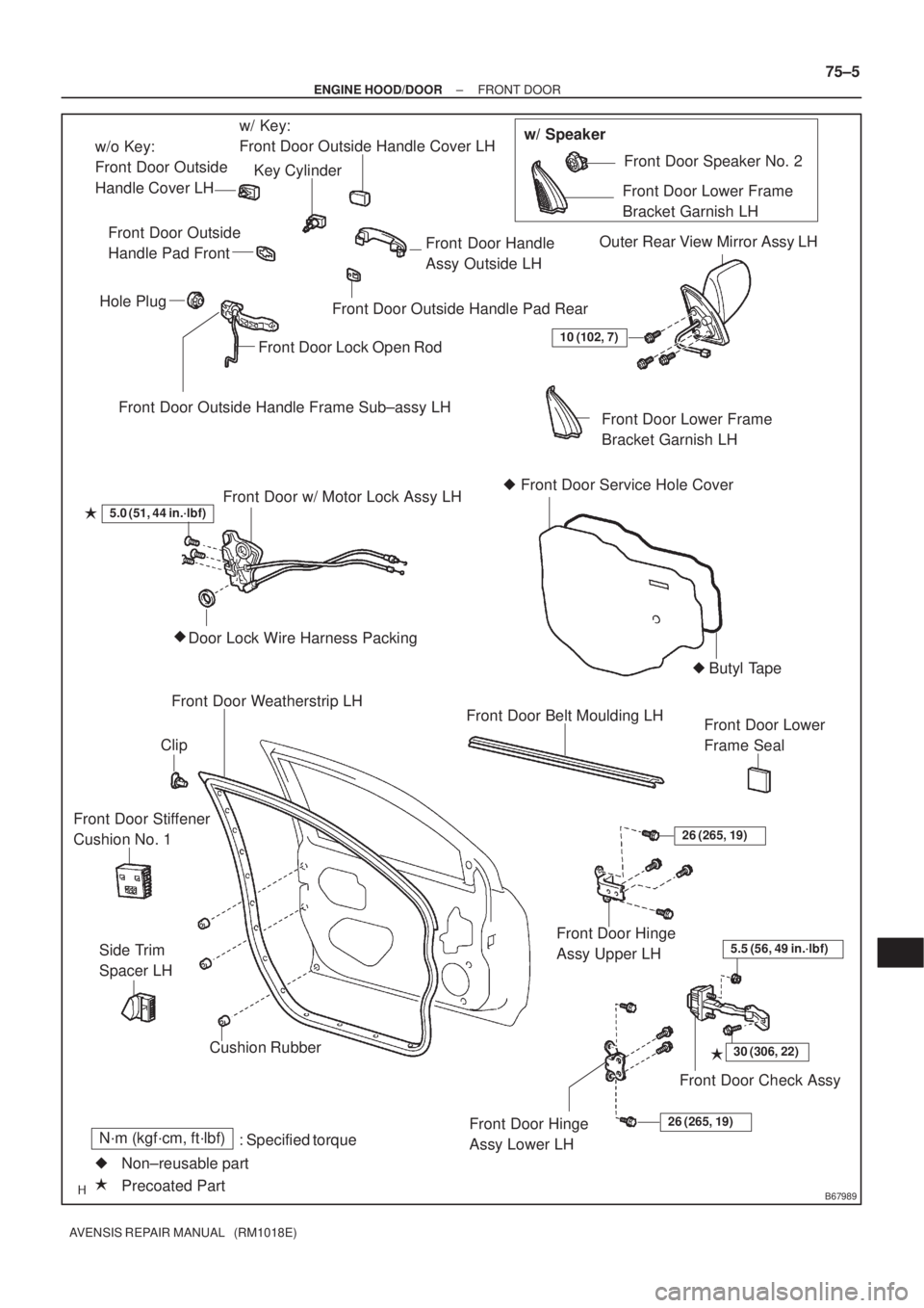
B67989
Front Door Outside Handle Frame Sub±assy LHw/ Key:
Front Door Outside Handle Cover LH
Front Door Handle
Assy Outside LH
Front Door Outside Handle Pad Rear Front Door Outside
Handle Pad Front
Hole Plug
Front Door Lock Open Rod
Front Door w/ Motor Lock Assy LH
Door Lock Wire Harness Packing �5.0 (51, 44 in.´lbf)
Front Door Belt Moulding LH
Front Door Hinge
Assy Upper LH
Front Door Check Assy
30 (306, 22)�
5.5 (56, 49 in.´lbf)
Front Door Hinge
Assy Lower LH26 (265, 19)
Front Door Weatherstrip LH
Cushion RubberFront Door Lower Frame
Bracket Garnish LH Outer Rear View Mirror Assy LH
Front Door Speaker No. 2
Front Door Service Hole Cover �
: Specified torqueN´m (kgf´cm, ft´lbf)
�
Precoated Part Non±reusable part �Clip
26 (265, 19)
Front Door Lower
Frame Seal
�
Butyl Tape
�
10 (102, 7)
Front Door Stiffener
Cushion No. 1
Side Trim
Spacer LH
Key Cylinder
w/o Key:
Front Door Outside
Handle Cover LHw/ Speaker
Front Door Lower Frame
Bracket Garnish LH
± ENGINE HOOD/DOORFRONT DOOR
75±5
AVENSIS REPAIR MANUAL (RM1018E)
Page 3407 of 5135
B66992
B66994
B66995
±
ENGINE HOOD/DOOR BACK DOOR(LIFTBACK MODELS)
75±39
AVENSIS REPAIR MANUAL (RM1018E)
(c)Horizontally and vertically adjust the door by loosening
the 8 door side hinge bolts.
(d)Tighten the door side hinge bolts after the adjustment.
Torque: 19.5 N �m (200 kgf �cm, 14 ft �lbf)
(e)Remove the floor finish plate (See page 76±45)
(f) Adjust the striker position by slightly loosening the striker mounting screws and hitting the striker with a plastic±
faced hammer.
(g) Tighten the striker mounting screws after the adjustment. Torque: 11.5 N �m (120 kgf �cm, 8 ft �lbf)
(h) Adjust the side female stopper so that the door can be opened/closed smoothly, as shown in the illustration.
(i) Tighten the side female stopper after the adjustment. Torque: 5.5 N �m (56 kgf �cm, 49 in. �lbf)
Page 3409 of 5135

750N3±01
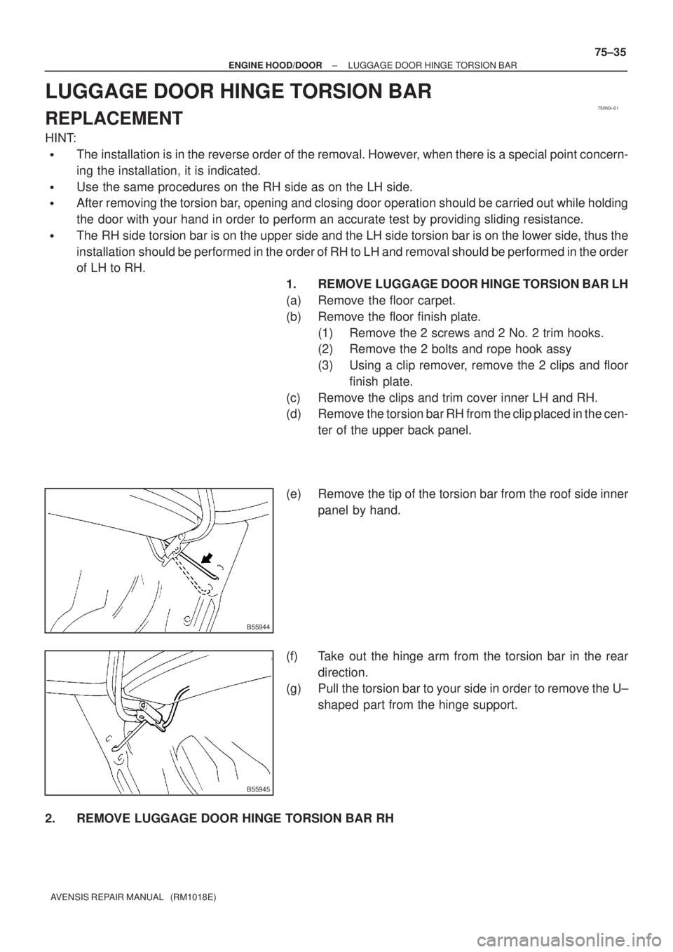
B55944
B55945
± ENGINE HOOD/DOORLUGGAGE DOOR HINGE TORSION BAR
75±35
AVENSIS REPAIR MANUAL (RM1018E)
LUGGAGE DOOR HINGE TORSION BAR
REPLACEMENT
HINT:
�The installation is in the reverse order of the removal. However, when there is a special point concern-
ing the installation, it is indicated.
�Use the same procedures on the RH side as on the LH side.
�After removing the torsion bar, opening and closing door operation should be carried out while holding
the door with your hand in order to perform an accurate test by providing sliding resistance.
�The RH side torsion bar is on the upper side and the LH side torsion bar is on the lower side, thus the
installation should be performed in the order of RH to LH and removal should be performed in the order
of LH to RH.
1. REMOVE LUGGAGE DOOR HINGE TORSION BAR LH
(a) Remove the floor carpet.
(b) Remove the floor finish plate.
(1) Remove the 2 screws and 2 No. 2 trim hooks.
(2) Remove the 2 bolts and rope hook assy
(3) Using a clip remover, remove the 2 clips and floor
finish plate.
(c) Remove the clips and trim cover inner LH and RH.
(d) Remove the torsion bar RH from the clip placed in the cen-
ter of the upper back panel.
(e) Remove the tip of the torsion bar from the roof side inner
panel by hand.
(f) Take out the hinge arm from the torsion bar in the rear
direction.
(g) Pull the torsion bar to your side in order to remove the U±
shaped part from the hinge support.
2. REMOVE LUGGAGE DOOR HINGE TORSION BAR RH
Page 5097 of 5135
B66033
B660325 Clamps
or
or or
or
or
or 71–12
– INSTRUMENT PANEL/METERINSTRUMENT PANEL SUB–ASSY LOWER (From
February, 2004)
AVENSIS REPAIR MANUAL SUPPLEMENT
(RM1098E)
34. REMOVE HEATER TO REGISTER DUCT NO.2
(a) Remove the screw , clip and the heater to register duct
No.2.
35. REMOVE INSTRUMENT PANEL LOWER ASSY
(a) Disconnect the hood lock control cable.
(b) Using a clip remover, remove the 2 clips.
(c) Remove the 2 bolts and 7 screws or .
(d) Disengage the 5 wire harness clamps.
(e) Remove the instrument panel lower assy.
36. REMOVE OUTER MIRROR SWITCH ASSY W/BEZEL
37. REMOVE FUSE BOX OPENING COVER
38. REMOVE GLOVE BOX LAMP ASSY
39. REMOVE INSTRUMENT PANEL BRACKET SUB–ASSY CENTER
(a) Remove the screw and the instrument panel bracket sub–assy center.