Page 1566 of 5135
I36642
14
C10 1
IC1
P±B MPX2
P±B 22
DCTY KSW
13
DB8
DA
B
J10B
J10 J/C
R
R14
IC2R
1 D9 Door Courtesy SWY1 2U1
Unlock Warning SW
W±B
(*7) W±B
(*5)
IL IO MPX1 11
P 10
IC1 29
A13 20
A15
3 24
A16 MPX±
PBLT A/C Control Assembly
F19 Front Passenger's
Seat Belt Warning Light
*1: Except Automatic A/C
*2: Automatic A/C
*3: 1AZ±FSE
*4: 1AZ±FE, 1ZZ±FE, 3ZZ±FE
*5: 1CD±FTV
*6: Except 1AZ±FE
*7: Except (*5) B±PBEW
PBEWA13 (*2) (*1)
(*1) (*2)P
B9
Buckle SwitchAirbag Sensor AssemblyDriver Side J/B
12
IC114
DB2
DD
L±R L±R
G±Y
W±B 3
1BKL 9
4
14
A28
3
A28L±R
DBEWA27
RBE+
RBE±
G±Y (*6)8
IC3
G±Y (*6)3
1
W±B (*6)
BSI14
Driver Side J/B (Body ECU)Combination Meter Assy RHD Models:
3
2L±R (*6)
W±B (*6)
W±B (*6)C
J31J/C
B
J30J22
J/C
CC B10 Front Seat Inner Belt Assy
(Occupant Detection Sensor)
± DIAGNOSTICSCOMBINATION METER
05±1531
AVENSIS REPAIR MANUAL (RM1018E)
Page 1567 of 5135

05±1532
±
DIAGNOSTIC SCOMBIN ATION METER
A VENSIS RE PAIR MANUAL (RM1018E)
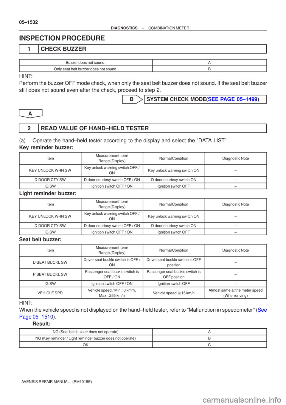
INSPECTIO N PROCEDURE
1 CHEC K BUZZER
Buzze r does not sound.A
Only seat belt buzzer does not sound.B
HIN T:
Perform the buzzer OFF mode check, when only the seat belt buzzer does n\
ot sound. If the seat belt buzzer
still does not sound even after the check, proceed to step 2.
BSYSTEM CHECK MODE( SEE PAGE 05±1499 )
A
2 READ V ALUE OF HAND±HELD TESTER
(a ) Operate the hand±held tester according to the display and select the \
ºD ATA LISTº.
Key reminder buzzer:
ItemMeasuremen t Item/
Range (Display)Normal ConditionDiagnostic Note
KEY UNLOCK WRN SWKey unlock warning switch OFF / ONKey unlock warning switch ON±
D DOOR CTY SWD door courtesy switch OFF / OND door courtesy switch ON±
IG SWIgnition switch OFF / ONIgnition switch OFF±
Light reminder buzzer:
ItemMeasurement Item/
Range (Display)Normal ConditionDiagnostic Note
KEY UNLOCK WRN SWKey unlock warning switch OFF / ONKey unlock warning switch ON±
D DOOR CTY SWD door courtesy switch OFF / OND door courtesy switch ON±
IG SWIgnition switch OFF / ONIgnition switch OFF±
Seat belt buzzer:
ItemMeasuremen t Item/
Range (Display)Normal ConditionDiagnostic Note
D SE AT BUCKL SWDriver seat buckle switch is OFF /
ONDriver seat buckle switch is OFFposition±
P SEAT BUCKL SWPassenger seat buckle switch is
OFF / ONPassenger seat buckle switch isOFF position±
IG SWIgnition switch OFF / ONIgnition switch OFF±
VEHICLE SPDVehicle speed / Min.: 0 km/h,
Max.: 255 km/hVehicle speed �15 km/hAlmost same at the meter speed
(When driving)
HINT:
Whe n the vehicle speed is not displayed on the hand±held teste r, refer to ºMalfunction in speedometerº ( See
Page 05±1510 ).
Result:
NG (Seat belt buzzer does not operate)A
NG (Key reminder / Light reminder buzzer does not operate)B
OKC
Page 1568 of 5135
±
DIAGNOSTICS COMBINATION METER
05±1533
AVENSIS REPAIR MANUAL (RM1018E)
BGo to step 5
CCHECK AND REPLACE COMBINATION METER
ASSY
A
3INSPECT FRONT SEAT INNER BELT ASSY(D±SEAT)(SEE PAGE 05±1594)
NGCHECK AND REPLACE FRONT SEAT INNER BELT ASSY
OK
4INSPECT FRONT SEAT INNER BELT ASSY(P±SEAT)(SEE PAGE 05±1594)
NGCHECK AND REPLACE FRONT SEAT INNER BELT ASSY
OK
REPAIR OR REPLACE HARNESS OR CONNECTOR
5INSPECT IGNITION SWITCH AND KEY UNLOCK WARNING SWITCH(SEE PAGE 05±1594)
NGCHECK AND REPLACE IGNITION SWITCH AND
KEY UNLOCK WARNING SWITCH
OK
6INSPECT DOOR COURTESY LAMP SWITCH ASSY(SEE PAGE 05±1594)
NG CHECK AND REPLACE DOOR COURTESY LAMP SWITCH ASSY
OK
REPAIR OR REPLACE HARNESS OR CONNECTOR
Page 1589 of 5135
B66771
KSW
W±B8 U1
Unlock Warning Switch Assy
W±B
IP5
+B GROUND 1
W±R W±B
2
1Instrument Panel J/B Assy
PRG
RDA 16
2PRG
RDA D6
Door Control Receiver
7Integration
Relay
IC2 I14 3 G±Y
L±W 16
7
To
Battery
DA Y
IO*
1
6 8
Center
J/BIC2 G±Y
L±W
CA CD
AJ16
J/C LHD Models
19 I14
A W±B
IL*
2*1: Gasoline Engine
*2: 1CD±FTV
± DIAGNOSTICSWIRELESS DOOR LOCK CONTROL SYSTEM
05±1575
AVENSIS REPAIR MANUAL (RM1018E)
ONLY WIRELESS CONTROL FUNCTION DOES NOT OPERATE
(PREPARE NEW OR NORMAL TRANSMITTER OF THE SAME
TYPE VEHICLE)
CIRCUIT DESCRIPTION
The door control receiver receives a signal from the transmitter and sends this signal to the integration relay.
Then, the integration relay controls door operation by sending a door LOCK/UNLOCK signal and a luggage
door (back door) unlock signal to each door lock motor.
WIRING DIAGRAM
05BNB±01
Page 1590 of 5135
B66770
KSW
W±B8 U1
Unlock Warning Switch Assy
IP 5
+B GROUND 1
W±R W±B
2 1Instrument Panel J/B Assy
PRG
RDA 16
2PRG
RDA D6
Door Control Receiver
7Integration
Relay
IC2 I14 3
G±Y
L±W 16
7
To
Battery
DA Y*
2
IKIC2 G±Y
L±W
13 6
CF CA19 RHD Models
DJ22
J/C*
2
D
Center J/B
W±B Y*2
*1: 1AZ±FE
*
2: Except 1AZ±FEY*
1
A
J15
J/CI14 05±1576
± DIAGNOSTICSWIRELESS DOOR LOCK CONTROL SYSTEM
AVENSIS REPAIR MANUAL (RM1018E)
Page 1591 of 5135

±
DIAGNOSTICS WIRELESS DOOR LOCK CONTROL SYSTEM
05±1577
AVENSIS REPAIR MANUAL (RM1018E)
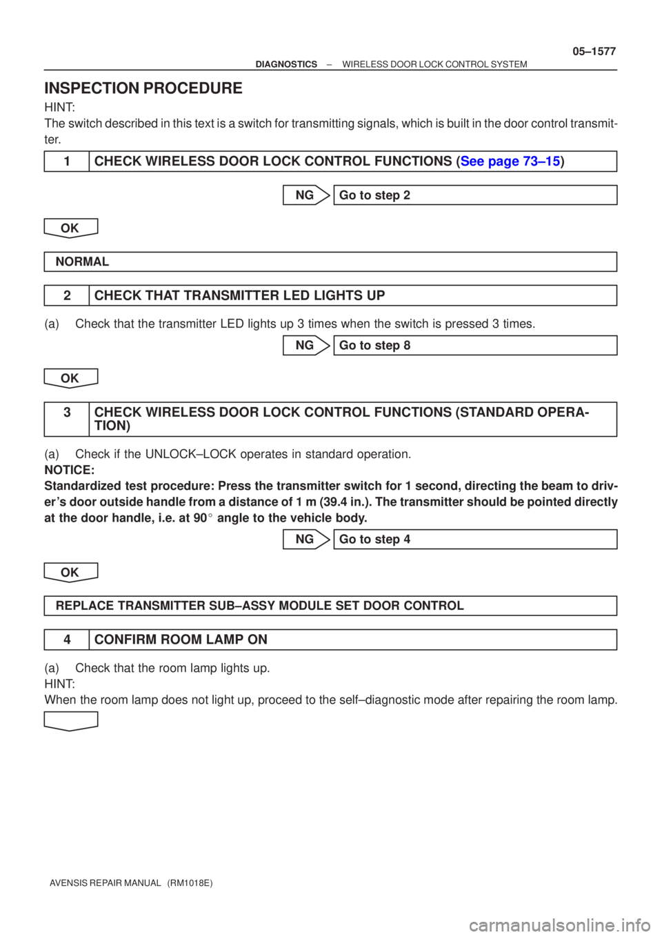
INSPECTION PROCEDURE
HINT:
The switch described in this text is a switch for transmitting signals, whi\
ch is built in the door control transmit-
ter.
1CHECK WIRELESS DOOR LOCK CONTROL FUNCTIONS (See page 73±15)
NG Go to step 2
OK
NORMAL
2 CHECK THAT TRANSMITTER LED LIGHTS UP
(a) Check that the transmitter LED lights up 3 times when the switch is pres\
sed 3 times. NG Go to step 8
OK
3 CHECK WIRELESS DOOR LOCK CONTROL FUNCTIONS (STANDARD OPERA- TION)
(a) Check if the UNLOCK±LOCK operates in standard operation.
NOTICE:
Standardized test procedure: Press the transmitter switch for 1 second, directing the beam to driv-
er 's door outside handle from a distance of 1 m (39.4 in.). The transmitte\
r should be pointed directly
at the door handle, i.e. at 90 � angle to the vehicle body.
NG Go to step 4
OK
REPLACE TRANSMITTER SUB±ASSY MODULE SET DOOR CONTROL
4 CONFIRM ROOM LAMP ON
(a) Check that the room lamp lights up.
HINT:
When the room lamp does not light up, proceed to the self±diagnostic mode\
after repairing the room lamp.
Page 1592 of 5135

B52341
Room LampOFF a: 0.25 sec.
b: 0.5 sec.
ON
ab
05±1578
±
DIAGNOSTICS WIRELESS DOOR LOCK CONTROL SYSTEM
AVENSIS REPAIR MANUAL (RM1018E)
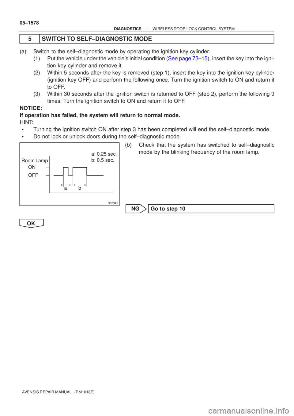
5 SWITCH TO SELF±DIAGNOSTIC MODE
(a) Switch to the self±diagnostic mode by operating the ignition key cylinder. (1)Put the vehicle under the vehicle's initial condition (See page 73±15), insert the key into the igni-
tion key cylinder and remove it.
(2) Within 5 seconds after the key is removed (step 1), insert the key int\
o the ignition key cylinder (ignition key OFF) and perform the following once: Turn the ignition switch to ON and return it
to OFF.
(3) Within 30 seconds after the ignition switch is returned to OFF (step 2)\
, perform the following 9
times: Turn the ignition switch to ON and return it to OFF.
NOTICE:
If operation has failed, the system will return to normal mode.
HINT:
�Turning the ignition switch ON after step 3 has been completed will end t\
he self±diagnostic mode.
�Do not lock or unlock doors during the self±diagnostic mode.
(b) Check that the system has switched to self±diagnosticmode by the blinking frequency of the room lamp.
NG Go to step 10
OK
Page 1593 of 5135

Room Lamp Output
Normal wave of UNLOCK switchUnmatching recognition code
No diagnosis outputs ON
OFF
T1: 0.25 sec. Wave is being received ON
OFF
OFF T1 T1 T1 T2 Normal wave of LOCK switch
ON
OFF
T1 T2
Normal wave of luggage door (back door)
unlock switch
ON
OFF
T2
T2
T2: 0.5 sec. Room Lamp Output
Room Lamp OutputRoom Lamp Output
Room Lamp Output
± DIAGNOSTICSWIRELESS DOOR LOCK CONTROL SYSTEM
05±1579
AVENSIS REPAIR MANUAL (RM1018E)
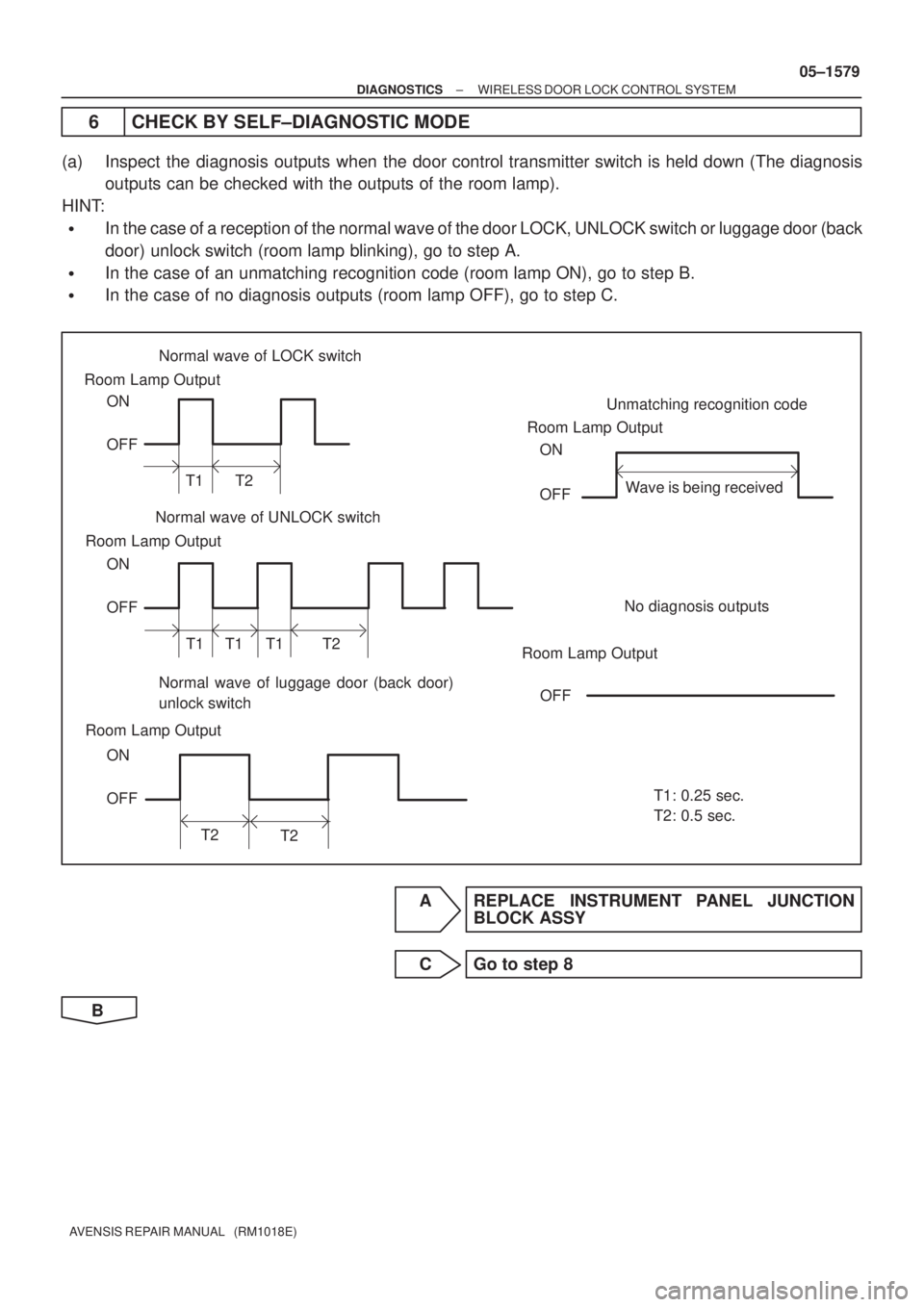
6 CHECK BY SELF±DIAGNOSTIC MODE
(a) Inspect the diagnosis outputs when the door control transmitter switch is held down (The diagnosis
outputs can be checked with the outputs of the room lamp).
HINT:
�In the case of a reception of the normal wave of the door LOCK, UNLOCK switch or luggage door (back
door) unlock switch (room lamp blinking), go to step A.
�In the case of an unmatching recognition code (room lamp ON), go to step B.
�In the case of no diagnosis outputs (room lamp OFF), go to step C.
A REPLACE INSTRUMENT PANEL JUNCTION
BLOCK ASSY
C Go to step 8
B