Page 4364 of 5135

A84847
EP1EP2VPA2
VCP1
VPA1VCP2 A20
Wire Harness Side (RHD):
Front View Accelerator Pedal Position Sensor
Connector
A84847
EP1
EP2VPA2
VCP1
VPA1 VCP2 A20 Accelerator Pedal Position Sensor
Connector
Wire Harness Side (LHD):
Front View
A81091
E9
ECM ConnectorVPA
VCPA
VPA2
EPA2
VCP2EPA
05−522
− DIAGNOSTICSECD SYSTEM (1CD−FTV)(From September, 2003)
AVENSIS Supplement (RM1045E)
20 CHECK HARNESS AND CONNECTOR(ACCELERATOR PEDAL POSITION
SENSOR−ECM)
(a) Disconnect the A20 accelerator pedal position sensor
connector.
(b) Disconnect E9 the ECM connector.
(c) Check the resistance between the wire harness side con-
nectors.
Standard (Check for open) (RHD):
Tester ConnectionSpecified Condition
VPA1(A20−5)−VPA (E9−22)
EP1(A20−1)−EPA (E9−28)
VCP1(A20−4)−VCPA (E9−26)Below1�VPA2 (A20−2)−VPA2 (E9−23)Below1�
EP2 (A20−3)−EPA2 (E9−29)
VCP2 (A20−6)−VCP2 (E9−27)
Standard (Check for open) (LHD):
Tester ConnectionSpecified Condition
VPA1(A20−5)−VPA (E9−22)
EP1(A20−3)−EPA (E9−28)
VCP1(A20−6)−VCPA (E9−26)Below1�VPA2 (A20−2)−VPA2 (E9−23)Below1�
EP2 (A20−1)−EPA2 (E9−29)
VCP2 (A20−4)−VCP2 (E9−27)
Standard (Check for short) (RHD):
Tester ConnectionSpecified Condition
VPA1(A20−5) or VPA (E9−22)−Body ground
EP1(A20−1) or EPA (E9−28)−Body ground
VCP1(A20−4) or VCPA (E9−26)−Body ground10k�orhigherVPA2 (A20−2) or VPA2 (E9−23)−Body ground10k�or higher
EP2 (A20−3) or EPA2 (E9−29)−Body ground
VCP2 (A20−6) or VCP2 (E9−27)−Body ground
Standard (Check for short) (LHD):
Tester ConnectionSpecified Condition
VPA1(A20−5) or VPA (E9−22)−Body ground
EP1(A20−3) or EPA (E9−28)−Body ground
VCP1(A20−6) or VCPA (E9−26)−Body ground10k�orhigherVPA2 (A20−2) or VPA2 (E9−23)−Body ground10k�or higher
EP2 (A20−1) or EPA2 (E9−29)−Body ground
VCP2 (A20−4) or VCP2 (E9−27)−Body ground
(d) Reconnect the accelerator pedal position sensor connec-
tor.
(e) Reconnect the ECM connector.
NG REPAIR OR REPLACE HARNESS OR
CONNECTOR
OK
REPLACE ACCELERATOR PEDAL ASSY (ACCELERATOR PEDAL POSITION SENSOR)
(See page10−66 of Pub. No. RM1018E AVENSIS REPAIR MANUAL)
Page 4365 of 5135

30
20
1 0
5
3
2
1
0.5
0.3
0.2
0. 1
−20 0
20 40 60
80 100
F 1474 1(− 4) ( 104) ( 140) ( 176)
(32) (68) (2 12)
30
20
1 0
0.5
0.3
0.2
0. 1
−20
20 40 60
80 100
F 1474 1(− 4) ( 104) ( 140) ( 176)
(32) (68) (2 12)
A56276
Temperature _ C( _ F)
Resistance k �
Acceptable
A79038
E2S PCR2 VC2
VC PC E2
Fuel Pressure Sensor
Component Side:
F16
−
DIAGNOSTICS ECD SYSTEM (1CD −FTV)(From September, 2003)
05 −523
AVENSIS Supplement (RM 1045E)
21 INSPECT DIESEL TURBO INLET AIR TENPERATURE SENSOR
(a) Remove the diesel turbo inlet air temperature sensor.
(b) Measure the resistance between the terminals.
Standard:
2.21 to 2.65 k � at 20 _C (68 _F)
(c) Reinstall the diesel turbo inlet air temperature sensor.
NG REPLACE DIESEL TURBO INLET AIR TENPERATURE SENSOR
OK
REPAIR OR REPLACE HARNESS OR CONNECTOR
22 INSPECT COMMON RAIL ASSY(FUEL PRESSURE SENSOR)
(a) Disconnect the F 16 fuel pressure sensor connector.
(b) Measure the resistance between each terminal of the fuel
pressure sensor connector.
Standard:
Tester ConnectionSpecified Condition
PC (F 16− 5) − E2 (F 16− 4)16.4 k � or less
PCR2 (F 16− 2) − E2S (F 16− 3)16.4 k � or less
PC (F 16− 5) − VC (F 16− 6)3k � or less
PCR2 (F 16− 2) − VC2 (F 16−1 )3k � or less
(c) Reconnect the fuel pressure sensor connector.
NG REPLACE COMMON RAIL ASSY (FUEL PRES- SURE SENSOR) (See page 11− 67)
OK
Page 4366 of 5135

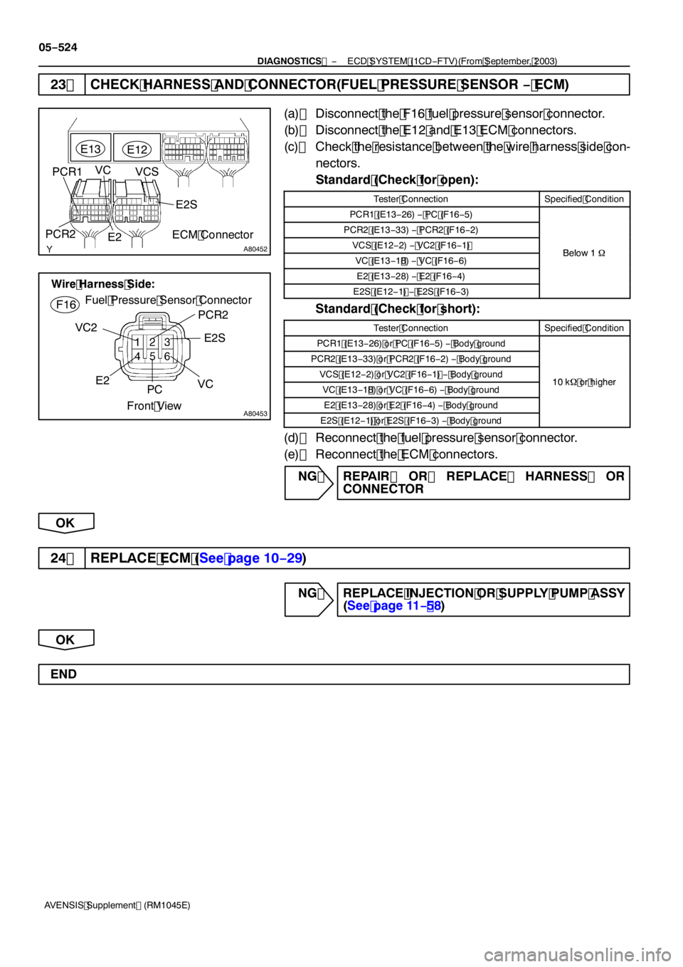
A80452
PCR1E
13
ECM Connector
E
12PCR2
E2VCS
E2S
VC
A80453
E2
PCR2
F
16
Wire Harness Side:
Fuel Pressure Sensor Connector
VC2
PCE2S
VC
Front View
05 −524
−
DIAGNOSTICS ECD SYSTEM (1CD −FTV)(From September, 2003)
AVENSIS Supplement (RM 1045E)
23 CHECK HARNESS AND CONNECTOR(FUEL PRESSURE SENSOR − ECM)
(a) Disconnect the F 16 fuel pressure sensor connector.
(b) Disconnect the E 12 and E 13 ECM connectors.
(c) Check the resistance between the wire harness side con-
nectors.
Standard (Check for open):
Tester ConnectionSpecified Condition
PCR1 (E 13− 26) − PC (F 16− 5)
PCR2 (E 13− 33) − PCR2 (F 16− 2)
VCS (E 12− 2) − VC2 (F 16−1 )Below1�VC (E 13−1 8)− VC (F 16− 6)Below 1�
E2 (E 13− 28) − E2 (F 16− 4)
E2S (E 12−1 )− E2S (F 16− 3)
Standard (Check for short):
Tester ConnectionSpecified Condition
PCR 1 (E 13− 26) or PC (F 16− 5) − Body ground
PCR2 (E 13− 33) or PCR2 (F 16 − 2) − Body ground
VCS (E 12− 2) or VC2 (F 16 −1 )− Body ground10 k � or higherVC (E 13−1 8) or VC (F 16− 6) − Body ground10k � or higher
E2 (E 13− 28) or E2 (F 16− 4) − Body ground
E2S (E 12−1 ) or E2S (F 16− 3) − Body ground
(d) Reconnect the fuel pressure sensor connector.
(e) Reconnect the ECM connectors.
NG REPAIR OR REPLACE HARNESS OR CONNECTOR
OK
24 REPLACE ECM (See page 10− 29)
NG REPLACE INJECTION OR SUPPLY PUMP ASSY
(See page 11− 58)
OK
END
Page 4367 of 5135
A81015
Engine
Room
R/B No. 1W
9ECM
W
E912
1 2
B
B−W22 1
3
Battery4
2 DH 6
B−R B−R
C11
Combination
Meter Assy
Check
Engine
Warning
Light AM2
IG2
AM2
Driver
Side
J/B
FL MAINEngine
Room
R/B
No. 3
3B 1A 1B−R
IE41
(LHD)IP11
(RHD)
18 DA
J8C
(LHD)J26A
(RHD)J8C
(LHD)J26A
(RHD) J/CB−W IGNI13
Ignition
Switch
− DIAGNOSTICSECD SYSTEM (1CD−FTV)(From September, 2003)
05−497
AVENSIS Supplement (RM1045E)
CHECK ENGINE WARNING LIGHT CIRCUIT
CIRCUIT DESCRIPTION
If the ECM detects a trouble, the CHK ENG is illuminated. At this time, the ECM records the DTC in its
memory.
WIRING DIAGRAM
INSPECTION PROCEDURE
HINT:
Troubleshoot each trouble symptom in accordance with the chart below .
Reference:
ResultProceed to
CHK ENG remains onStart inspection from step 1
CHK ENG is not illuminatedStart inspection from step 3
05B62−07
Page 4368 of 5135

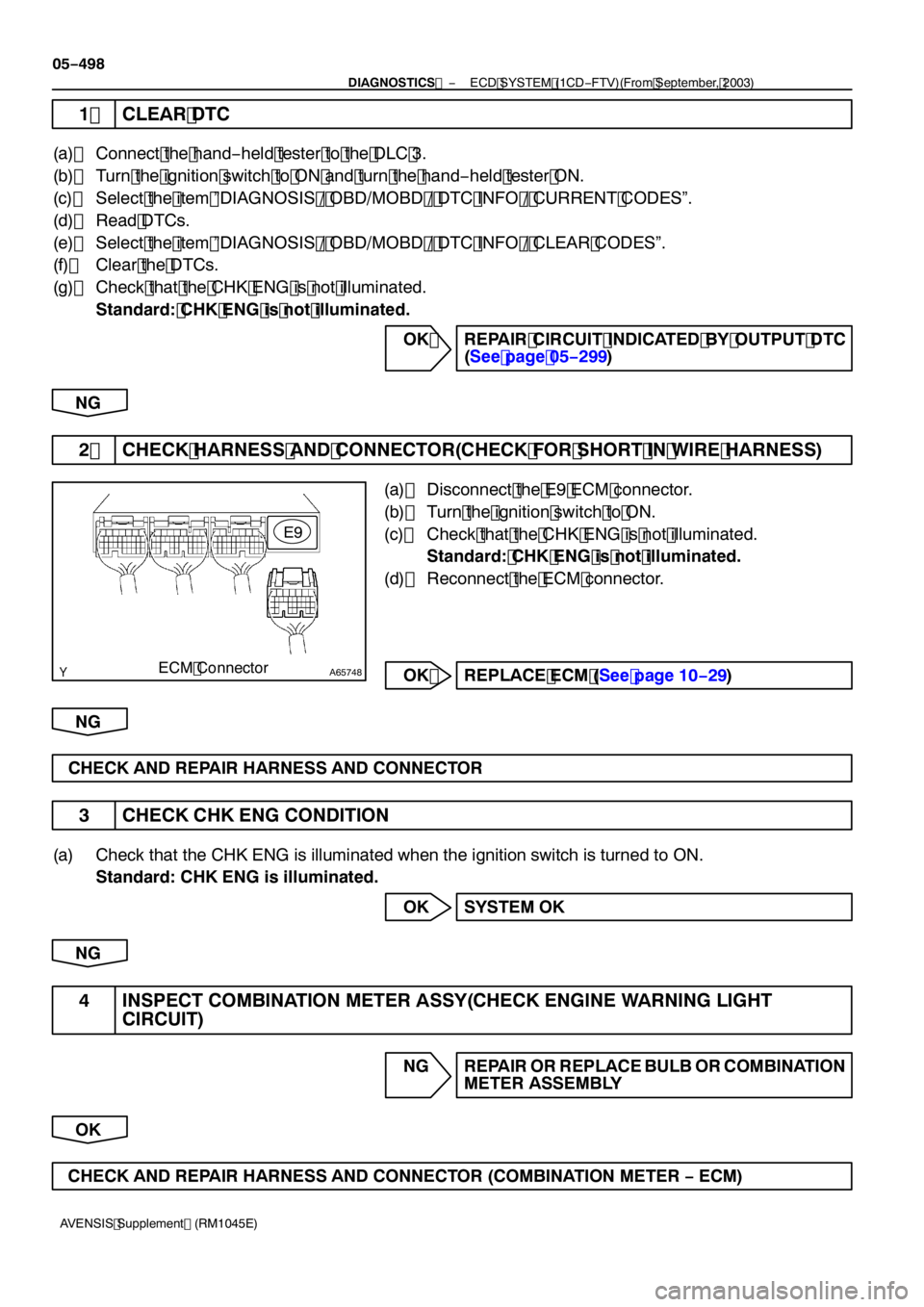
A65748ECM ConnectorE9
05
−498
−
DIAGNOSTICS ECD SYSTEM (1CD−FTV)(From September, 2003)
AVENSIS Supplement (RM1045E)
1 CLEAR DTC
(a) Connect the hand −held tester to the DLC 3.
(b) Turn the ignition switch to ON and turn the hand −held tester ON.
(c) Select the item ”DIAGNOSIS / OBD/MOBD / DTC INFO / CURRENT CODES”.
(d) Read DTCs.
(e) Select the item ”DIAGNOSIS / OBD/MOBD / DTC INFO / CLEAR CODES”.
(f) Clear the DTCs.
(g) Check that the CHK ENG is not illuminated. Standard: CHK ENG is not illuminated.
OK REPAIR CIRCUIT INDICATED BY OUTPUT DTC(See page 05 −299)
NG
2 CHECK HARNESS AND CONNECTOR(CHECK FOR SHORT IN WIRE HARNESS)
(a) Disconnect the E9 ECM connector.
(b) Turn the ignition switch to ON.
(c) Check that the CHK ENG is not illuminated. Standard: CHK ENG is not illuminated.
(d) Reconnect the ECM connector.
OK REPLACE ECM (See page 10− 29)
NG
CHECK AND REPAIR HARNESS AND CONNECTOR
3 CHECK CHK ENG CONDITION
(a) Check that the CHK ENG is illuminated when the ignition switch is turned to ON. Standard: CHK ENG is illuminated.
OK SYSTEM OK
NG
4 INSPECT COMBINATION METER ASSY(CHECK ENGINE WARNING LIGHT CIRCUIT)
NG REPAIR OR REPLACE BULB OR COMBINATION
METER ASSEMBLY
OK
CHECK AND REPAIR HARNESS AND CONNECTOR (COMBINATION METER −ECM)
Page 4369 of 5135
A81016
ECM
STA
E97
B−Y
IJW−BJ12
B B
J13
J/C W−B 1 5
32 1AM2 2
B
B−R1
S51
S4
Starter
Battery7IK1
FL MAIN 3 3
Engine Room
R/B No. 3
B B 55
55 1
11A
BB−R
IE41
(LHD)IP11
(RHD)B−R
Engine
Room
R/B No. 1
Driver
Side R/B ST
Relay
2
DJ
9
DADriver
Side J/B B−R
B−RI13
Ignition Switch
4
5
AM2 ST2B−Y
B−Y
6
2ST 1
6 Fuse
Block
B−WB−YB−Y B−Y
J12
A C
J13C
J13 05−494
− DIAGNOSTICSECD SYSTEM (1CD−FTV)(From September, 2003)
AVENSIS Supplement (RM1045E)
STARTER SIGNAL CIRCUIT
CIRCUIT DESCRIPTION
HINT:
While the engine is being cranked, current flows from terminal ST2 of the ignition switch to the ST relay coil
and also current flows to terminal STA of the ECM (STA signal).
WIRING DIAGRAM
05I7V−01
Page 4370 of 5135
−
DIAGNOSTICS ECD SYSTEM (1CD−FTV)(From September, 2003)
05 −495
AVENSIS Supplement (RM1045E)
INSPECTION PROCEDURE
HINT:
This chart is on the premise that the engine is cranked normally. If the engine is not cranked, proceed to the
problem symptoms table on page 05 −282.
1 READ VALUE OF HAND −HELD TESTER(STA SIGNAL)
(a) Connect the hand −held tester to the DLC3.
(b) Turn the ignition switch to ON and turn the hand −held tester ON.
(c) Select the item ”DIAGNOSIS / OBD/MOBD / DATA LIST / ALL / STARTER SIG” and read its value dis-
played on the hand −held tester.
Standard:
Ignition Switch PositionONSTART
STARTER SIGOFFON
OK PROCEED TO NEXT CIRCUIT INSPECTION SHOWN PROBLEM SYMPTOMS TABLE
(See page 05 −282)
NG
Page 4371 of 5135
A65748
STAE9
ECM Connector
A79097
ST Relay
Driver Side R/B LHD:
A79098
ST Relay
Driver Side R/B RHD:
05
−496
−
DIAGNOSTICS ECD SYSTEM (1CD−FTV)(From September, 2003)
AVENSIS Supplement (RM1045E)
2 CHECK HARNESS AND CONNECTOR(ECM − ST RELAY)
(a) Disconnect the E9 ECM connector.
(b) Remove the ST relay from the driver side R/B.
(c) Check the resistance between the wire harness side con-
nectors.
Standard (Check for open):
Tester ConnectionSpecified Condition
ST relay (1) − STA (E9 −7)Below 1 �
Standard (Check for short):
Tester ConnectionSpecified Condition
ST relay (1) or STA (E9 −7) − Body ground10 k � or higher
(d) Reconnect the ECM connector.
(e) Reinstall the ST relay.
NG REPAIR OR REPLACE HARNESS OR CONNECTOR
OK
REPLACE ECM (See page 10− 29)