Page 557 of 5135

A76869
Engine Room J/B No. 1 and
Engine Room R/B No. 1
E9
E11 B±GECM
B±Y
BATT
Battery FL MAINEFI
1 4B1
BR
EEE1 3
BR 1A
B±GEngine Room
J/B No. 4 1 4A2 1 1
1IE37
IO17
(LHD)(RHD)B±Y
± DIAGNOSTICSSFI SYSTEM (1AZ±FSE)
05±467
AVENSIS REPAIR MANUAL (RM1018E)
DTC P0560 SYSTEM VOLTAGE
CIRCUIT DESCRIPTION
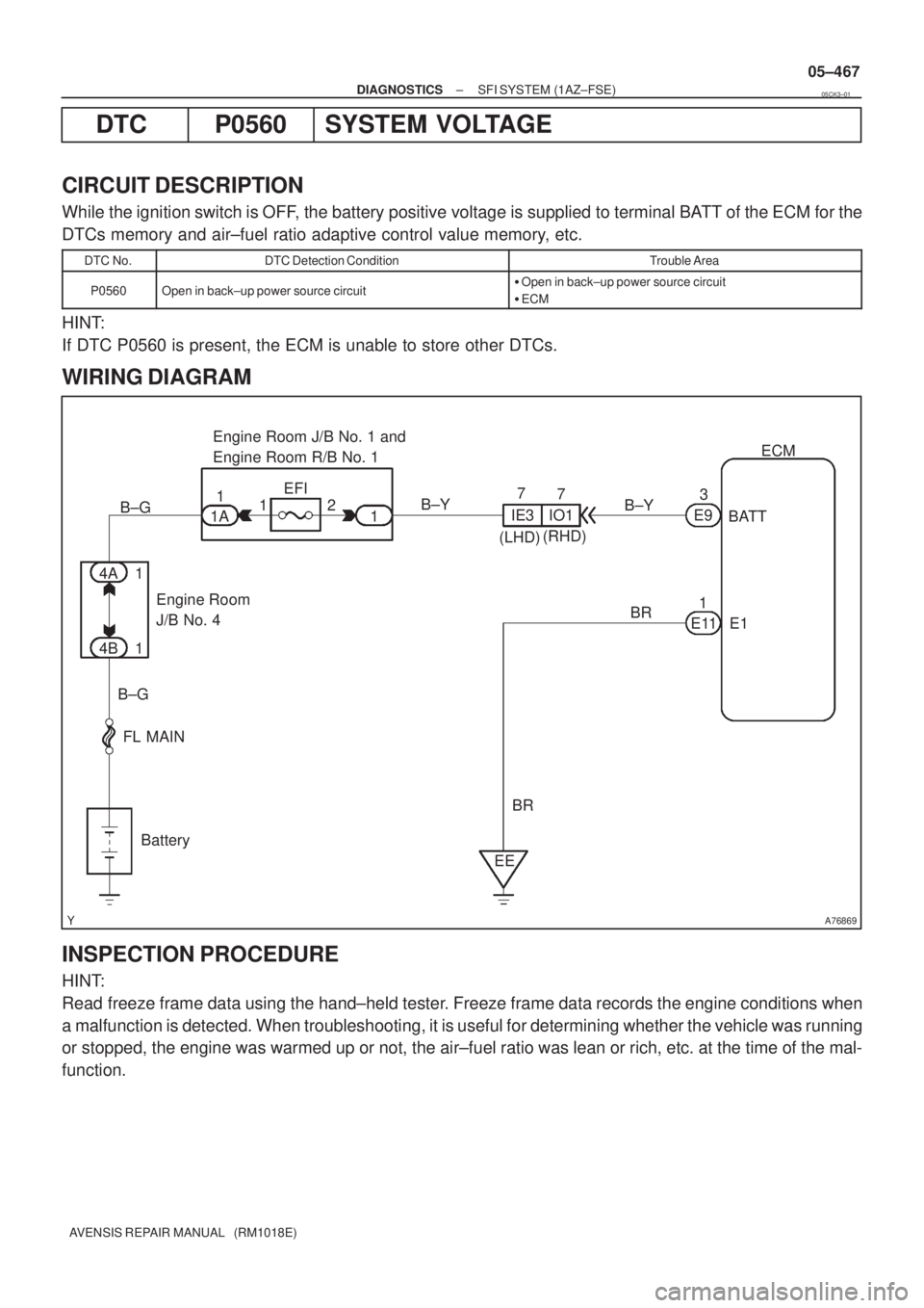
While the ignition switch is OFF, the battery positive voltage is supplied to terminal BATT of the ECM for the
DTCs memory and air±fuel ratio adaptive control value memory, etc.
DTC No.DTC Detection ConditionTrouble Area
P0560Open in back±up power source circuit�Open in back±up power source circuit
�ECM
HINT:
If DTC P0560 is present, the ECM is unable to store other DTCs.
WIRING DIAGRAM
INSPECTION PROCEDURE
HINT:
Read freeze frame data using the hand±held tester. Freeze frame data records the engine conditions when
a malfunction is detected. When troubleshooting, it is useful for determining whether the vehicle was running
or stopped, the engine was warmed up or not, the air±fuel ratio was lean or rich, etc. at the time of the mal-
function.
05CK3±01
Page 560 of 5135

A81711
ECMManifold Absolute
Pressure Sensor
Brake Booster
Air Cleaner Case
Throttle
Valve
To Cylinder
Intake Manifold Check ValveBrake Booster
Pressure Sensor
05±462
±
DIAGNOSTICS SFI SYSTEM(1AZ±FSE)
AVENSIS REPAIR MANUAL (RM1018E)
DTCP0556BRAKE BOOSTER PRESSURE SENSOR CIRCUIT RANGE/PERFORMANCE
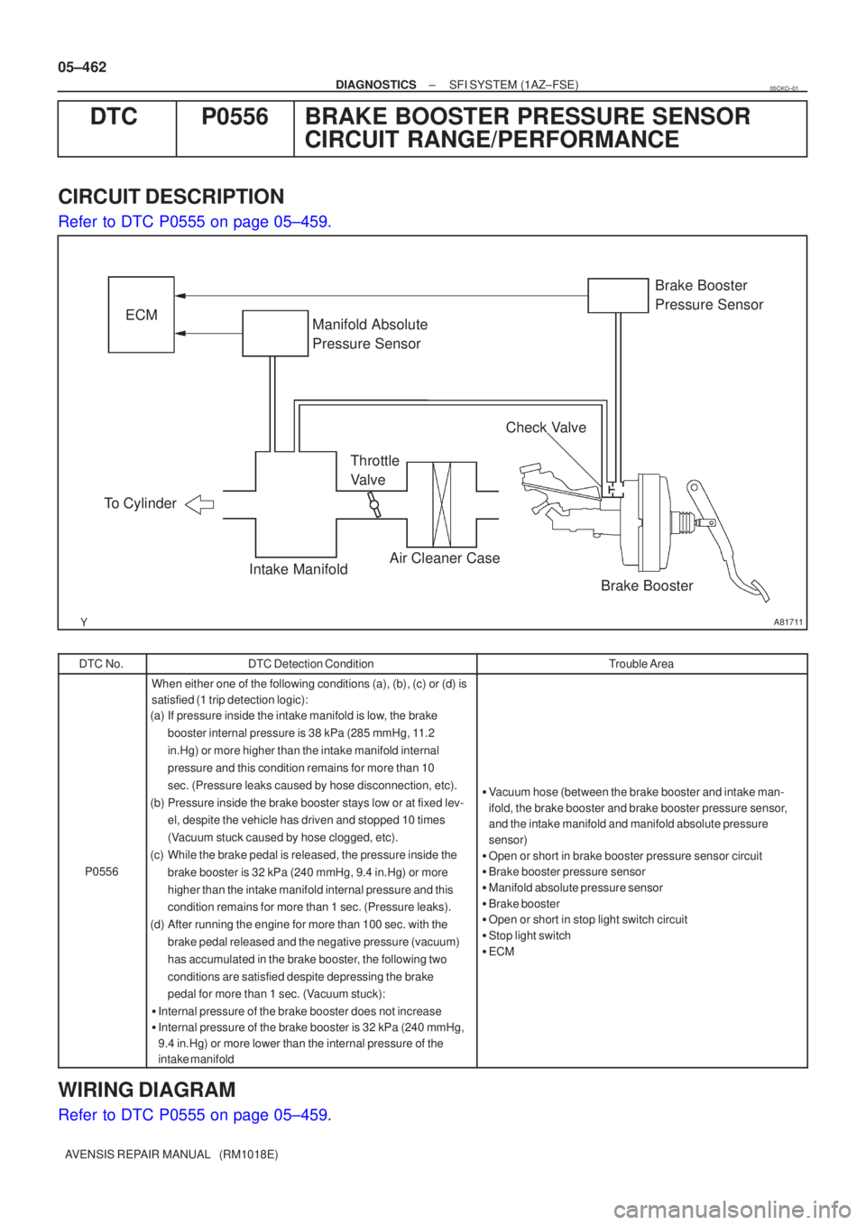
CIRCUIT DESCRIPTION
Refer to DTC P0555 on page 05±459.
DTC No.DTC Detection ConditionTrouble Area
P0556
When either one of the following conditions (a), (b), (c) or (d)\
is
satisfied (1 trip detection logic):
(a) If pressure inside the intake manifold is low, the brake
booster internal pressure is 38 kPa (285 mmHg, 11.2
in.Hg) or more higher than the intake manifold internal
pressure and this condition remains for more than 10
sec. (Pressure leaks caused by hose disconnection, etc).
(b) Pressure inside the brake booster stays low or at fixed lev- el, despite the vehicle has driven and stopped 10 times
(Vacuum stuck caused by hose clogged, etc).
(c) While the brake pedal is released, the pressure inside the brake booster is 32 kPa (240 mmHg, 9.4 in.Hg) or more
higher than the intake manifold internal pressure and this
condition remains for more than 1 sec. (Pressure leaks).
(d) After running the engine for more than 100 sec. with the brake pedal released and the negative pressure (vacuum)
has accumulated in the brake booster, the following two
conditions are satisfied despite depressing the brake
pedal for more than 1 sec. (Vacuum stuck):
� Internal pressure of the brake booster does not increase
� Internal pressure of the brake booster is 32 kPa (240 mmHg,
9.4 in.Hg) or more lower than the internal pressure of the
intake manifold
�Vacuum hose (between the brake booster and intake man-
ifold, the brake booster and brake booster pressure sensor,
and the intake manifold and manifold absolute pressure
sensor)
� Open or short in brake booster pressure sensor circuit
� Brake booster pressure sensor
� Manifold absolute pressure sensor
� Brake booster
� Open or short in stop light switch circuit
� Stop light switch
� ECM
WIRING DIAGRAM
Refer to DTC P0555 on page 05±459.
05CKO±01
Page 562 of 5135

A76903
PB (+)E2 (±)ECM Connector
E13
05±464
±
DIAGNOSTICS SFI SYSTEM(1AZ±FSE)
AVENSIS REPAIR MANUAL (RM1018E)
NGCHECK AND REPAIR STOP LIGHT SWITCH CIRCUIT
OK
4CHECK VACUUM HOSE(BRAKE BOOSTER PRESSURE SENSOR ± BRAKE BOOSTER, INTAKE MANIFOLD ± BRAKE BOOSTER)
(a)Check that the vacuum hoses are connected correctly.
(b)Check that the vacuum hoses are not loose or disconnected.
(c)Check the vacuum hoses and tubes for clogs, cracks, holes, damage, or bl\
ockage.
NGREPAIR OR REPLACE VACUUM HOSE
OK
5INSPECT ECM(PB VOLTAGE)
(a)Disconnect the vacuum hose from the brake booster pressure sensor.
(b)Turn the ignition switch ON.
(c)Using the MITYVAC (Hand±Held Vacuum Pump), apply a vacuum to the brake booster pressure sensor, measure
the voltage between the specified terminals of the E13
ECM connector.
Standard:
Symbols (Terminal No.)Vacuum pump operationSpecified condition
0 kPa
(0 mmHg, 0 in.Hg)3.3 to 3.9 V
PB (E13±26) ± E2 (E13±28)40 kPa
(300 mmHg, 11.8 in.Hg)2.1 to 2.7 V()
80 kPa
(600 mmHg, 23.6 in.Hg)0.9 to 1.5 V
NGGo to step 6
OK
CHECK FUNCTION OF BRAKE BOOSTER (See page 32±17, 32±21)
Page 565 of 5135

A76868
B2
Brake Booster Pressure Sensor18
E13 ECM
5V
E1
3
R±W
26
Y
2
1
BR 28
E2PB
VC
PIM
E2 E13
E13
VC
R±W
Y
BR
9
EA1
11
10
EA1
EA1
±
DIAGNOSTICS SFI SYSTEM(1AZ±FSE)
05±459
AVENSIS REPAIR MANUAL (RM1018E)
DTCP0555BRAKE BOOSTER PRESSURE SENSOR
CIRCUIT
DTCP0557BRAKE BOOSTER PRESSURE SENSOR CIRCUIT LOW INPUT
DTCP0558BRAKE BOOSTER PRESSURE SENSOR CIRCUIT HIGH INPUT
CIRCUIT DESCRIPTION
The brake booster pressure sensor detects internal pressure of the brake bo\
oster as voltage. A structure
of the sensor and its connection to the ECM are the same as ones for the i\
ntake air pressure sensor. (Refer
to DTC P0105 on page 05±342).
In order to purify emission gas when starting a cold engine, drastically\
retard the ignition timing to quickly
activate tha catalyst. Upon this, the throttle valve is opened larger than the throttle opening angle with\
a warm
engine, therefore the intake manifold pressure will be closer to atmospheric pr\
essure. If the negative pres-
sure (vacuum) applied inside the brake booster drops, the ECM cancels the drastic retarding timing and
introduces the negative pressure (vacuum) into the intake manifold, and the ECM \
then resumes the drastic
retarding timing after the brake booster negative pressure (vacuum) is ensured \
at required level.
DTC No.DTC Detection ConditionTrouble Area
P0555Open or short in brake booster pressure sensor circuit for 5
sec. or more
�Open or short in brake booster pressure sensor circuit
P0557Open in brake booster pressure sensor circuit for 5 sec. or
more
Oen or short in brake booster ressure sensor circuit
�Brake booster pressure sensor
� Vacuum hose
P0558Short in brake booster pressure sensor circuit for 5 sec. or
more�ECM
WIRING DIAGRAM
05CKN±01
Page 568 of 5135
± DIAGNOSTICSSFI SYSTEM (1AZ±FSE)
05±455
AVENSIS REPAIR MANUAL (RM1018E)
DTC P0504 BRAKE SWITCH ºAº/ºBº CORRELATION
CIRCUIT DESCRIPTION
In this system, the signal of the stop light switch is used to judge whether the acceleration system is abnormal
or not.
The stop light switch has a duplex system (signals STP and ST1±) to memorize the abnormality when the
signals of depressing and releasing the brake pedal are detected simultaneously.
HINT:
Normal condition is as shown in the table.
SignalBrake pedal releasedIn transitionBrake pedal depressed
STPOFFONON
ST1±ONONOFF
DTC No.DTC Detection ConditionTrouble Area
P0504
Condition (a), (b) and (c) continue for 0.5 sec. or more:
(a) Ignition switch ON
(b) Brake pedal released
(c) STP signal is OFF when the ST1± signal is OFF�Short in stop light switch signal circuit
�Stop light switch
�ECM
05CJ5±01
Page 570 of 5135

A81707
Free Pushed in
43 21
A72880
Brake Pedal
DepressedBrake Pedal
Released
ST1± (+)
E11
E1 (±)
E10
ECM Connector
± DIAGNOSTICSSFI SYSTEM (1AZ±FSE)
05±457
AVENSIS REPAIR MANUAL (RM1018E)
1 CHECK OPERATION OF STOP LIGHT
(a) Check if the stop lights go on and off normally when the brake pedal is depressed and released.
NG REPAIR OR REPLACE STOP LAMP SWITCH
CIRCUIT
OK
2 INSPECT STOP LIGHT SWITCH ASSY
(a) Check for continuity between each pair of the terminals.
Standard:
Switch positionTerminal No.Specified condition
Switchpin free1 ± 2ContinuitySwitch pin free3 ± 4No continuity
Switchpinpushed in1 ± 2No continuitySwitch pin pushed in3 ± 4Continuity
NG REPLACE STOP LIGHT SWITCH ASSY
OK
3 READ VALUE OF HAND±HELD TESTER(STP SIGNAL AND ST1± VOLTAGE)
(a) Turn the ignition switch ON.
(b) Select the item ºDIAGNOSIS / OBD/MOBD / DATA LIST
/ ALL / STOP LIGHT SWº and read its value displayed on
the hand±held tester.
Standard:
Brake PedalSpecified condition
DepressedSTP Signal ON
ReleasedSTP Signal OFF
(c) Measure the voltage between the specified terminals of
the E10 and E11 ECM connectors.
Standard:
Symbols (Terminal No.)Brake pedalSpecified condition
ST1± (E10±12) DepressedBelow 1.5 VST1 (E10 12)
± E1 (E11±1)
Released7.5 to 14 V
NG Go to step 4
OK
CHECK FOR INTERMITTENT PROBLEMS
Page 572 of 5135

A81703
From
Speed SensorSkid
Control
ECU4±Pulse
Combination
MeterECM 4±Pulse
A76866
Combination MeterECM
C11V±W
SPD 17
V±W
E10 J/C
18 H
J10
(LHD)J20H
(RHD)H
J10
(LHD)J20H
(RHD)
± DIAGNOSTICSSFI SYSTEM (1AZ±FSE)
05±453
AVENSIS REPAIR MANUAL (RM1018E)
DTC P0500 VEHICLE SPEED SENSOR ºAº
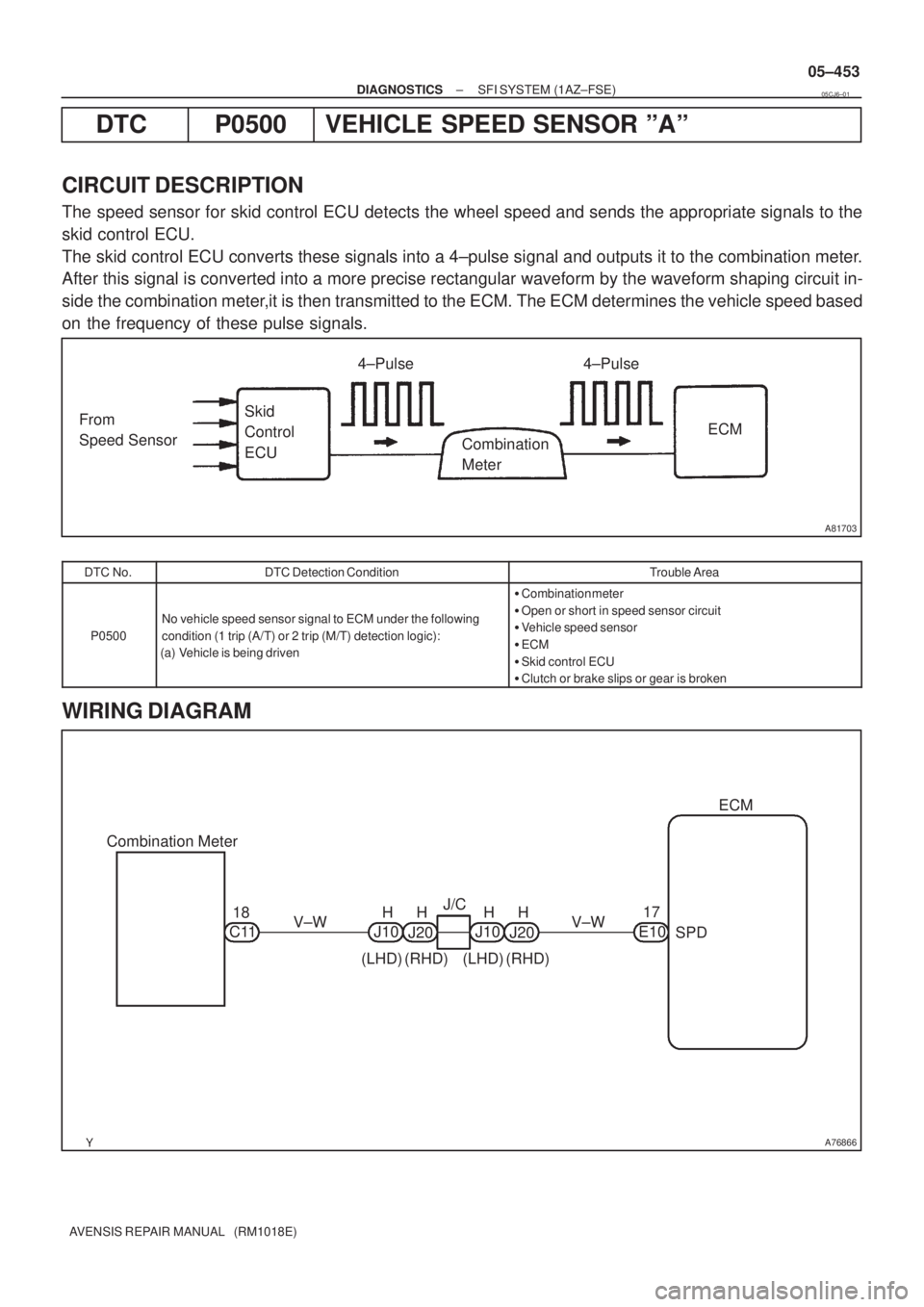
CIRCUIT DESCRIPTION
The speed sensor for skid control ECU detects the wheel speed and sends the appropriate signals to the
skid control ECU.
The skid control ECU converts these signals into a 4±pulse signal and outputs it to the combination meter.
After this signal is converted into a more precise rectangular waveform by the waveform shaping circuit in-
side the combination meter,it is then transmitted to the ECM. The ECM determines the vehicle speed based
on the frequency of these pulse signals.
DTC No.DTC Detection ConditionTrouble Area
P0500
No vehicle speed sensor signal to ECM under the following
condition (1 trip (A/T) or 2 trip (M/T) detection logic):
(a) Vehicle is being driven
�Combination meter
�Open or short in speed sensor circuit
�Vehicle speed sensor
�ECM
�Skid control ECU
�Clutch or brake slips or gear is broken
WIRING DIAGRAM
05CJ6±01
Page 573 of 5135

A59661
E01 (±)SPD (+)
ECM Connector
E13
E10
A81704
4.5 to
5.5V
0V Turn Wheel
05±454
±
DIAGNOSTICS SFI SYSTEM(1AZ±FSE)
AVENSIS REPAIR MANUAL (RM1018E)
INSPECTION PROCEDURE
HINT:
Read freeze frame data using the hand±held tester. Freeze frame data records the engine conditions when
a malfunction is detected. When troubleshooting, it is useful for determi\
ning whether the vehicle was running
or stopped, the engine was warmed up or not, the air±fuel ratio was lea\
n or rich, etc. at the time of the mal-
function.
1CHECK OPERATION OF SPEEDOMETER
(a)Drive the vehicle and check if the operation of the speedometer in the combination meter is normal.
HINT:
The vehicle speed sensor is operating normally if the speedometer displa\
y is normal. NGCHECK SPEEDOMETER CIRCUIT (See page 05±1510)
OK
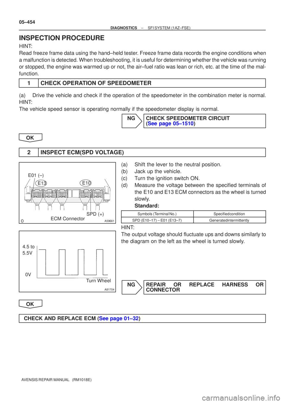
2INSPECT ECM(SPD VOLTAGE)
(a)Shift the lever to the neutral position.
(b)Jack up the vehicle.
(c)Turn the ignition switch ON.
(d)Measure the voltage between the specified terminals of the E10 and E13 ECM connectors as the wheel is turned
slowly.
Standard:
Symbols (Terminal No.)Specified condition
SPD (E10±17) ± E01 (E13±7)Generated intermittently
HINT:
The output voltage should fluctuate ups and downs similarly to
the diagram on the left as the wheel is turned slowly.
NGREPAIR OR REPLACE HARNESS OR CONNECTOR
OK
CHECK AND REPLACE ECM (See page 01±32)