Page 574 of 5135

2
W±G EFI No. 2 1
B±G
W±B
ECW±B
4A
14B11AEFI
1B±Y
1
2 4
4
44
4
4
B±W Engin")
A76875
ECM
EVP1 34
E13 EFI Relay
1 1 23
Engine Room
J/B No. 4B±W
1MREL 8
E9
Battery FL MAIN B±G2 5
GR
V5
VSV (EVAP)
2
W±G EFI No. 2 1
B±G
W±B
ECW±B
4A
14B11AEFI
1B±Y
1
2 4
4
44
4
4
B±W Engine Room
R/B No. 1
and
Engine Room
J/B No. 1Engine Room R/B No. 4
GR
B±W
EA113IE1 2
± DIAGNOSTICSSFI SYSTEM (1AZ±FSE)
05±449
AVENSIS REPAIR MANUAL (RM1018E)
DTC P0443 EVAPORATIVE EMISSION CONTROL
SYSTEM PURGE CONTROL VALVE CIRCUIT
CIRCUIT DESCRIPTION
To reduce HC emissions, evaporated fuel from the fuel tank is routed through the charcoal canister to the
intake manifold for combustion in the cylinders.
The ECM changes the duty signal to the VSV for the EVAP so that the intake quantity of HC emissions is
appropriate for the driving conditions (engine load, engine speed, vehicle speed, etc.) after the engine is
warmed up.
DTC No.DTC Detection ConditionTrouble Area
P0443Proper response to ECM command does not occur
�Open of short in VSV circuit for EVAP
�VSV for EVAP
�ECM
WIRING DIAGRAM
05CK6±01
Page 577 of 5135
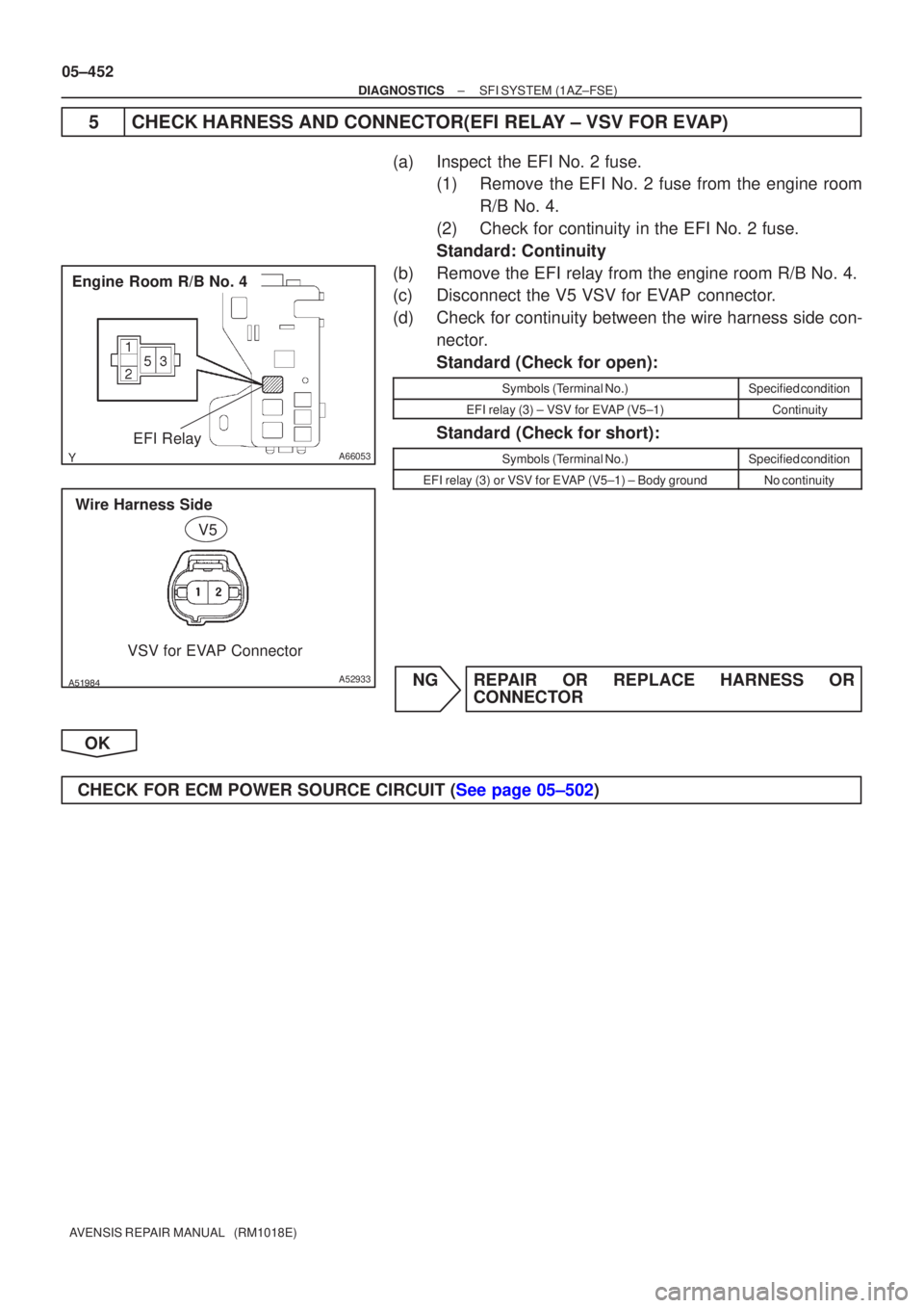
A66053
Engine Room R/B No. 4EFI Relay
������A52933
Wire Harness SideVSV for EVAP Connector
V5
05±452
±
DIAGNOSTICS SFI SYSTEM(1AZ±FSE)
AVENSIS REPAIR MANUAL (RM1018E)
5CHECK HARNESS AND CONNECTOR(EFI RELAY ± VSV FOR EVAP)
(a)Inspect the EFI No. 2 fuse. (1)Remove the EFI No. 2 fuse from the engine room
R/B No. 4.
(2)Check for continuity in the EFI No. 2 fuse.
Standard: Continuity
(b)Remove the EFI relay from the engine room R/B No. 4.
(c)Disconnect the V5 VSV for EVAP connector.
(d)Check for continuity between the wire harness side con- nector.
Standard (Check for open):
Symbols (Terminal No.)Specified condition
EFI relay (3) ± VSV for EVAP (V5±1)Continuity
Standard (Check for short):
Symbols (Terminal No.)Specified condition
EFI relay (3) or VSV for EVAP (V5±1) ± Body groundNo continuity
NGREPAIR OR REPLACE HARNESS OR CONNECTOR
OK
CHECK FOR ECM POWER SOURCE CIRCUIT (See page 05±502)
Page 578 of 5135

AVENSIS REPAIR MANUAL (RM1018E)
D")
A54278
Waveform of Heated Oxygen
Sensor before CatalystNormal CatalystWaveform of Heated
Oxygen Sensor
after Catalyst
05±446
± DIAGNOSTICSSFI SYSTEM (1AZ±FSE)
AVENSIS REPAIR MANUAL (RM1018E)
DTC P0420 CATALYST SYSTEM EFFICIENCY BELOW
THRESHOLD (BANK 1)
DTC P0430 CATALYST SYSTEM EFFICIENCY BELOW
THRESHOLD (BANK 2)
CIRCUIT DESCRIPTION
The ECM compares the waveform of the heated oxygen sensor located before the catalyst with the wave-
form of the heated oxygen sensor located after the catalyst to determine whether or not the catalyst perfor-
mance has deteriorated.
The air±fuel ratio feedback compensation keeps the waveform of the heated oxygen sensor before the cata-
lyst repeatedly changing back and forth from rich to lean.
If the catalyst is functioning normally, the waveform of the heated oxygen sensor after the catalyst switches
back and forth between rich and lean much more slowly than the waveform of the heated oxygen sensor
before the catalyst.
But when both waveforms change at a similar rate, it indicates that the catalyst performance has deterio-
rated.
DTC No.DTC Detection ConditionTrouble Area
P0420
P0430
After engine and catalyst are warmed up, and while vehicle is
driven within set value and engine speed range, waveforms of
heated oxygen sensors have the same amplitude
(2 trip detection logic)�Gas leakage in exhaust system
�Heated oxygen sensor
�Three±way catalytic converter (inside exhaust manifold)
HINT:
�Bank 1 refers to the No. 1 and No. 4 cylinders.
�Bank 2 refers to the No. 2 and No. 3 cylinders.
�Sensor 1 refers to the sensor closest to the engine assembly.
�Sensor 2 refers to the sensor farthest away from the engine assembly.
05CKM±01
Page 581 of 5135

05±439
AVENSIS REPAIR MANUAL (RM1018E)
DTC P0351 IGNITION COIL ºAº PRIMARY/SECONDARY
CIRCUIT
DTC P0352 IGNITION COIL ºBº PRIMARY/SECONDARY
CIRCUIT
DTC P0353")
± DIAGNOSTICSSFI SYSTEM (1AZ±FSE)
05±439
AVENSIS REPAIR MANUAL (RM1018E)
DTC P0351 IGNITION COIL ºAº PRIMARY/SECONDARY
CIRCUIT
DTC P0352 IGNITION COIL ºBº PRIMARY/SECONDARY
CIRCUIT
DTC P0353 IGNITION COIL ºCº PRIMARY/SECONDARY
CIRCUIT
DTC P0354 IGNITION COIL ºDº PRIMARY/SECONDARY
CIRCUIT
HINT:
�These DTCs indicate a malfunction related to primary circuit.
�If DTC P0351 is displayed, check No. 1 ignition coil with igniter circuit.
�If DTC P0352 is displayed, check No. 2 ignition coil with igniter circuit.
�If DTC P0353 is displayed, check No. 3 ignition coil with igniter circuit.
�If DTC P0354 is displayed, check No. 4 ignition coil with igniter circuit.
CIRCUIT DESCRIPTION
A Direct Ignition System (DIS) has been adopted. The DIS improves the ignition timing accuracy, reduces
high±voltage loss, and enhances the overall reliability of the ignition system by eliminating the distributor.
The DIS is a 1±cylinder ignition system which ignites one cylinder with one ignition coil. In the 1±cylinder
ignition system, the one spark plug is connected to the end of the secondary winding. High voltage generated
in the secondary winding is applied directly to the spark plug. The spark of the spark plug passes from the
center electrode to the ground electrode.
The ECM determines the ignition timing and outputs the ignition signals (IGT) for each cylinder. Based on
the IGT signals, the power transistors in the igniter cut off the current to the primary coil in the ignition coil
is supplied to the spark plug that is connected to the end of the secondary coil. At the same time, the igniter
also sends an ignition confirmation signal (IGF) as a fail±safe measure to the ECM.
05CKL±01
Page 582 of 5135
A73818
Crankshaft
Position
Sensor
Camshaft
Position
Sensor
Various
SensorIGT1
IGF
IGT2
IGT3
IGT4 ECM
IgniterFrom Battery
Ignition Coil
TA C
To Tachometer
No.2 Ignition
Coil with Igniter
No.3 Ignition
Coil with Igniter
No.4 Ignition
Coil with IgniterNo.1 Ignition Coil with Igniter
Spark Plug
No.1 Cylinder
No.4 Cylinder No.2 Cylinder
No.3 Cylinder 05±440
± DIAGNOSTICSSFI SYSTEM (1AZ±FSE)
AVENSIS REPAIR MANUAL (RM1018E)DTC No.
DTC Detection ConditionTrouble Area
P0351
P0352
P0353
P0354
No IGF signal to ECM while engine is running
�Ignition system
�Open or short in IGF and IGT circuit from ignition coil with
igniter to ECM (ignition coil circuit 1 through 4)
�Ignition coil with igniter (ignition coil 1 through 4)
�IG2 relay
�ECM
Page 587 of 5135
±
DIAGNOSTICS SFI SYSTEM(1AZ±FSE)
05±445
AVENSIS REPAIR MANUAL (RM1018E)
NGREPAIR OR REPLACE HARNESS OR
CONNECTOR
OK
CHECK FOR FUEL PUMP CONTROL CIRCUIT (See page 05±507)
Page 588 of 5135
A76880
FL MAIN
StarterCircuit
Opening Relay
Park/Neutral
Position SWIG2 Relay
AM2
BatteryECM
STA IGSW IGN Ignition SWFuel Pump
ST2IG2
ST
Relay
(NE Signal) (A/T)FC
IG2STTr
(M/T)
(A/T) AM2
± DIAGNOSTICSSFI SYSTEM (1AZ±FSE)
05±507
AVENSIS REPAIR MANUAL (RM1018E)
FUEL PUMP CONTROL CIRCUIT
CIRCUIT DESCRIPTION
In the diagram below, when the engine is cranked, current flows from terminal ST2 of the ignition switch to
the starter relay coil and also current flows to terminal STA of ECM (STA signal).
When the STA signal and NE signal are input to the ECM, Tr is turned ON, current flows to the coil of the
circuit opening relay, the relay switches on, power is supplied to the fuel pump and the fuel pump operates.
While the NE signal is generated (engine running), the ECM keeps Tr ON (circuit opening relay ON) and the
fuel pump also keeps operating.
05CK1±01
Page 589 of 5135
A76881
IE4B±R
I13
Ignition SW
AM2
FCECM
1
B±R
6 6 4
2
IB1 Engine Room
R/B No. 1
B±G
FL MAIN
BatteryB±R
ECW±B 1ADHE9 10
IC3
32 51
1
3 5
4B 1AM2
IG2
Relay
B±G
F25
Fuel
Pump 4
5
W±B 10 Engine
Room
R/B No. 4IG2
1
24 4
4 4 4A 1C8
Circuit
Opening
Relay 16 DLIGN B±R
(LHD)IP11
(RHD)
IG2
B±R
Driver
Side J/B
B 1
11
2 2
1
Engine Room
R/B No. 4
BR B±WB±WB±WB±W
L±BG±Y G±YG±Y 05±508
± DIAGNOSTICSSFI SYSTEM (1AZ±FSE)
AVENSIS REPAIR MANUAL (RM1018E)
WIRING DIAGRAM


05±445
AVENSIS REPAIR MANUAL (RM1018E)
NGREPAIR OR REPLACE HARNESS OR
CONNECTOR
OK
CHECK FOR FUEL PUMP CONTROL CIRCUIT (See page 05±507)")
 (A/T)FC
IG2STTr
(M/T)
(A/T) AM2
± DIAGNOS")
