Page 2147 of 5135
A77302
14±162
±
ENGINE MECHANICAL CYLINDER HEAD GASKET(1AZ±FE)
AVENSIS REPAIR MANUAL (RM1018E)
22.REMOVE ENGINE SERVICE COVER BRACKET RH (RHD(W/ AIR CONDITIONER) STEERING POSITION TYPE)
(a)Remove the bolt and the engine service cover bracket RH.
23.REMOVE CYLINDER HEAD COVER SUB±ASSY (See page 14±139)
24.SET NO. 1 CYLINDER TO TDC/COMPRESSION (See page 14±139)
25.REMOVE ENGINE MOUNTING BRACKET NO.2 RH (See page 14±139)
26.REMOVE TRANSVERSE ENGINE ENGINE MOUNTING INSULATOR (See page 14±139)
27.REMOVE CRANKSHAFT PULLEY (See page 14±139)
SST09213±54015 (91651±60855), 09330±00021, 09950±50013 (0995\
1±05010, 09952±05010, 09953±05020, 09954±05021)
28.REMOVE CHAIN TENSIONER ASSY NO.1 (See page 14±139)
29.REMOVE CRANKSHAFT POSITION SENSOR (See page 18±17)
30.REMOVE OIL PAN SUB±ASSY (See page 14±139) SST09032±00100
31.REMOVE V±RIBBED BELT TENSIONER ASSY (See page 14±139)
32.REMOVE TIMING CHAIN OR BELT COVER SUB±ASSY (See page 14±139)
33.REMOVE CRANKSHAFT POSITION SENSOR PLATE NO.1
34.REMOVE CHAIN TENSIONER SLIPPER
35.REMOVE CHAIN VIBRATION DAMPER NO.1
36.REMOVE TIMING CHAIN GUIDE (See page 14±139)
37.REMOVE CHAIN SUB±ASSY
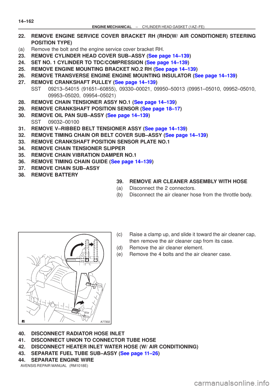
38.REMOVE BATTERY 39.REMOVE AIR CLEANER ASSEMBLY WITH HOSE
(a)Disconnect the 2 connectors.
(b)Disconnect the air cleaner hose from the throttle body.
(c)Raise a clamp up, and slide it toward the air cleaner cap,then remove the air cleaner cap from its case.
(d)Remove the air cleaner element.
(e)Remove the 4 bolts and the air cleaner case.
40.DISCONNECT RADIATOR HOSE INLET
41.DISCONNECT UNION TO CONNECTOR TUBE HOSE
42.DISCONNECT HEATER INLET WATER HOSE (W/ AIR CONDITIONING)
43.SEPARATE FUEL TUBE SUB±ASSY (See page 11±26)
44. SEPARATE ENGINE WIRE
Page 2201 of 5135
A77335
A77302
A77300
A77299
± ENGINE MECHANICALPARTIAL ENGINE ASSY (1AZ±FSE)
14±205
AVENSIS REPAIR MANUAL (RM1018E)
21. REMOVE AIR CLEANER ASSEMBLY WITH HOSE
(a) Disconnect the 2 connectors.
(b) Disconnect the 2 vacuum hoses.
(c) Disconnect the ventilation hose.
(d) Disconnect the air cleaner hose from the throttle body.
(e) Raise a clamp up, and slide it toward the air cleaner cap,
then remove the air cleaner cap from its case.
(f) Remove the air cleaner element.
(g) Remove the 4 bolts and the air cleaner case.
22. REMOVE BATTERY CARRIER
(a) Remove the 4 bolts and the battery carrier.
23. REMOVE RADIATOR RESERVE TANK SUB±ASSY
(a) Remove the 2 bolts and the radiator reserve tank.
24. SEPARATE RETURN TUBE SUB±ASSY
(a) Remove the 3 bolts shown in the illustration.
Page 2243 of 5135
A09687
UpwardCam Lobe
Clearance
A80107
A81553
Upward
Notch
Cam Lobe
Intake
Manifold
Side
±
ENGINE MECHANICAL VALVE CLEARANCE(1CD±FTV)
14±271
AVENSIS REPAIR MANUAL (RM1018E)
9.REMOVE INJECTION PIPE SUB±ASSY NO.2
SST09023±12700
HINT:
Perform the same procedures as injection pipe No. 1.
10.REMOVE INJECTION PIPE SUB±ASSY NO.3
SST09023±12700
HINT:
Perform the same procedures as injection pipe No. 1.
11.REMOVE INJECTION PIPE SUB±ASSY NO.4
SST09023±12700
HINT:
Perform the same procedures as injection pipe No. 1.
12.REMOVE CYLINDER HEAD COVER SUB±ASSY (See page 11±60)
13.REMOVE NOZZLE LEAKAGE PIPE ASSY (See page 11±60)
14.REMOVE INJECTOR ASSY (See page 11±60)
HINT:
Since each injector assembly has characteristic fuel injecting behavior, store them in correct order so that
they can be returned to the original locations when re±assembling.
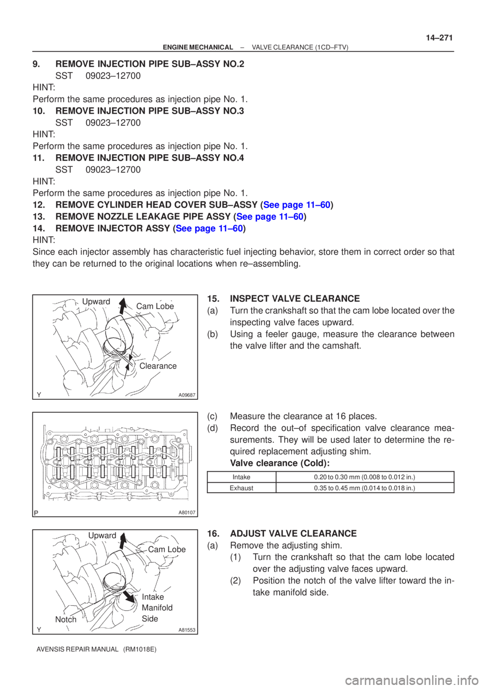
15. INSPECT VALVE CLEARANCE
(a) Turn the crankshaft so that the cam lobe located over theinspecting valve faces upward.
(b) Using a feeler gauge, measure the clearance between the valve lifter and the camshaft.
(c) Measure the clearance at 16 places.
(d) Record the out±of specification valve clearance mea- surements. They will be used later to determine the re-
quired replacement adjusting shim.
Valve clearance (Cold):
Intake0.20 to 0.30 mm (0.008 to 0.012 in.)
Exhaust0.35 to 0.45 mm (0.014 to 0.018 in.)
16. ADJUST VALVE CLEARANCE
(a) Remove the adjusting shim.(1) Turn the crankshaft so that the cam lobe located
over the adjusting valve faces upward.
(2) Position the notch of the valve lifter toward the in- take manifold side.
Page 2259 of 5135
A77302
A77353
±
ENGINE MECHANICAL CYLINDER HEAD GASKET(1AZ±FSE)
14±257
AVENSIS REPAIR MANUAL (RM1018E)
(e)Raise a clamp up, and slide it toward the air cleaner cap,
then remove the air cleaner cap from its case.
(f)Remove the air cleaner element.
(g)Remove the 4 bolts and the air cleaner case.
43.DISCONNECT RADIATOR HOSE INLET
44.DISCONNECT UNION TO CONNECTOR TUBE HOSE
45.DISCONNECT HEATER INLET WATER HOSE
46.SEPARATE FUEL TUBE SUB±ASSY
47.SEPARATE ENGINE WIRE
48.REMOVE THROTTLE BODY ASSY (See page 10±44)
49. REMOVE CHARCOAL CANISTER ASSY 50. REMOVE INTAKE MANIFOLD
(a) Remove the 5 bolts and 2 nuts.
(b) Disconnect the 2 vacuum hoses.
(c) Remove the 2 stud bolts.
(d) Remove the intake manifold and insulator.
51. REMOVE INTAKE AIR CONTROL VALVE ASSY
(a) Remove the intake air control valve and gasket.
52. REMOVE MANIFOLD CONVERTER INSULATOR NO.1
(a) Disconnect the oxygen sensor connector.
(b) Remove the 2 bolts and nut, and then remove the manifold insulator.
Page 2532 of 5135
C83023
C80293
30±26
±
DRIVE SHAFT / PROPELLER SHAFT FRONT AXLE HUB SUB±ASSY LH
AVENSIS REPAIR MANUAL (RM1018E)
19.INSTALL LOWER BALL JOINT ASSY FRONT LH
(a)Install the lower ball joint and torque the nut. Torque: 103 N �m (1,050 kgf �cm, 76 ft �lbf)
(b)Install a new cotter pin.
NOTICE:
If the holes for the cotter pin are not aligned, tighten the nut up to 6\
0 � further.
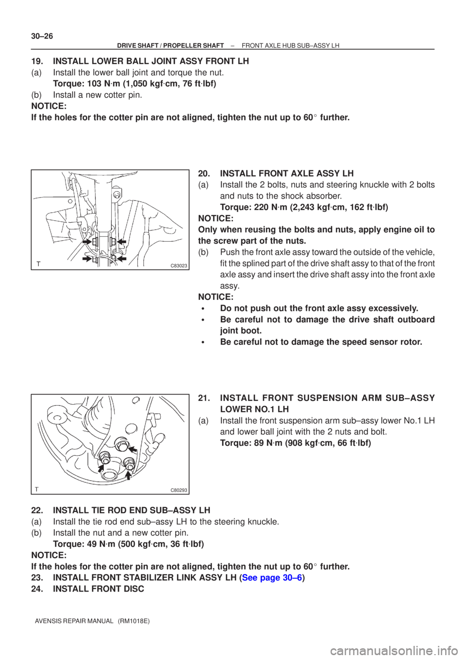
20.INSTALL FRONT AXLE ASSY LH
(a)Install the 2 bolts, nuts and steering knuckle with 2 bolts and nuts to the shock absorber.
Torque: 220 N �m (2,243 kgf �cm, 162 ft �lbf)
NOTICE:
Only when reusing the bolts and nuts, apply engine oil to
the screw part of the nuts.
(b)Push the front axle assy toward the outside of the vehicle, fit the splined part of the drive shaft assy to that of the front
axle assy and insert the drive shaft assy into the front axle
assy.
NOTICE:
�Do not push out the front axle assy excessively.
�Be careful not to damage the drive shaft outboard
joint boot.
�Be careful not to damage the speed sensor rotor.
21.INSTALL FRONT SUSPENSION ARM SUB±ASSY LOWER NO.1 LH
(a)Install the front suspension arm sub±assy lower No.1 LH and lower ball joint with the 2 nuts and bolt.
Torque: 89 N �m (908 kgf �cm, 66 ft �lbf)
22.INSTALL TIE ROD END SUB±ASSY LH
(a)Install the tie rod end sub±assy LH to the steering knuckle.
(b)Install the nut and a new cotter pin. Torque: 49 N �m (500 kgf �cm, 36 ft �lbf)
NOTICE:
If the holes for the cotter pin are not aligned, tighten the nut up to 6\
0 � further.
23.INSTALL FRONT STABILIZER LINK ASSY LH (See page 30±6)
24. INSTALL FRONT DISC
Page 2546 of 5135
C86268
SST
C67417
Matchmarks
30±16
± DRIVE SHAFT / PROPELLER SHAFTFRONT DRIVE SHAFT
AVENSIS REPAIR MANUAL (RM1018E)
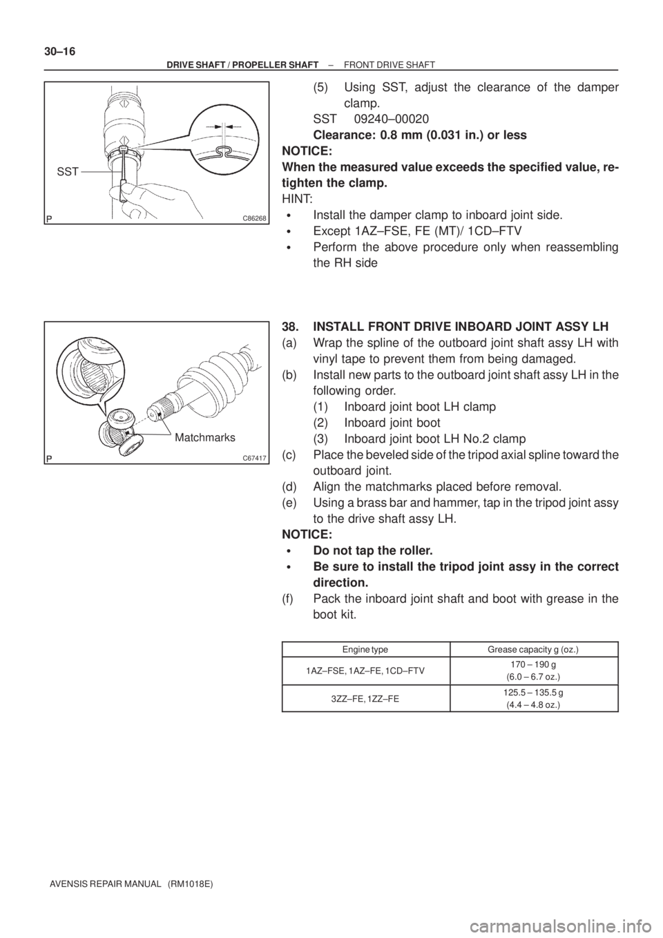
(5) Using SST, adjust the clearance of the damper
clamp.
SST 09240±00020
Clearance: 0.8 mm (0.031 in.) or less
NOTICE:
When the measured value exceeds the specified value, re-
tighten the clamp.
HINT:
�Install the damper clamp to inboard joint side.
�Except 1AZ±FSE, FE (MT)/ 1CD±FTV
�Perform the above procedure only when reassembling
the RH side
38. INSTALL FRONT DRIVE INBOARD JOINT ASSY LH
(a) Wrap the spline of the outboard joint shaft assy LH with
vinyl tape to prevent them from being damaged.
(b) Install new parts to the outboard joint shaft assy LH in the
following order.
(1) Inboard joint boot LH clamp
(2) Inboard joint boot
(3) Inboard joint boot LH No.2 clamp
(c) Place the beveled side of the tripod axial spline toward the
outboard joint.
(d) Align the matchmarks placed before removal.
(e) Using a brass bar and hammer, tap in the tripod joint assy
to the drive shaft assy LH.
NOTICE:
�Do not tap the roller.
�Be sure to install the tripod joint assy in the correct
direction.
(f) Pack the inboard joint shaft and boot with grease in the
boot kit.
Engine typeGrease capacity g (oz.)
1AZ±FSE, 1AZ±FE, 1CD±FTV170 ± 190 g
(6.0 ± 6.7 oz.)
3ZZ±FE, 1ZZ±FE125.5 ± 135.5 g
(4.4 ± 4.8 oz.)
Page 2740 of 5135
400DI±02
D25118
D25119
± AUTOMATIC TRANSMISSION / TRANSFLOOR SHIFT ASSY
40±69
AVENSIS REPAIR MANUAL (RM1018E)
ADJUSTMENT
1. INSPECT SHIFT LEVER POSITION
(a) When the shift lever from P to R position with the ignition switch is ON and the brake pedal is de-
pressed, make sure that the shifting lever moves smoothly and can be moderately operated.
(b) When starting engine, make sure that the vehicle moves forward when shifting from N to D position
and moves rearward when shifting to R position.
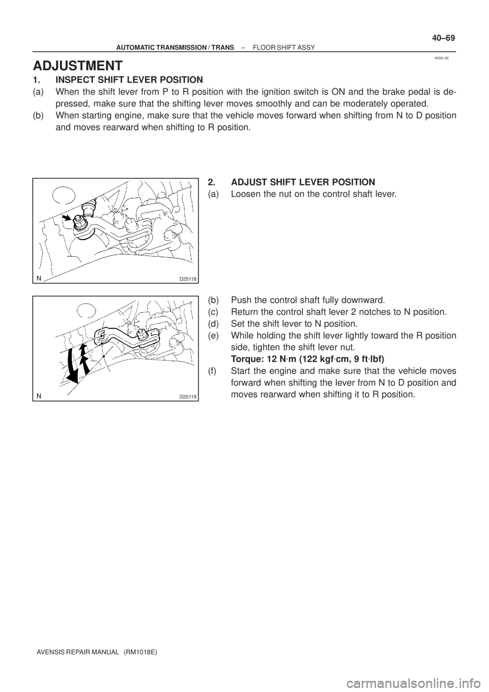
2. ADJUST SHIFT LEVER POSITION
(a) Loosen the nut on the control shaft lever.
(b) Push the control shaft fully downward.
(c) Return the control shaft lever 2 notches to N position.
(d) Set the shift lever to N position.
(e) While holding the shift lever lightly toward the R position
side, tighten the shift lever nut.
Torque: 12 N�m (122 kgf�cm, 9 ft�lbf)
(f) Start the engine and make sure that the vehicle moves
forward when shifting the lever from N to D position and
moves rearward when shifting it to R position.
Page 2809 of 5135
F44793Matchmarks
F44794
Screw
Extractor
F44795
SST
F44796
F44797
50±14
±
STEERING COLUMN STEERING COLUMN ASSY
AVENSIS REPAIR MANUAL (RM1018E)
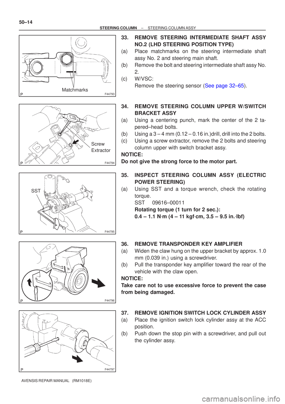
33. REMOVE STEERING INTERMEDIATE SHAFT ASSY NO.2 (LHD STEERING POSITION TYPE)
(a) Place matchmarks on the steering intermediate shaft
assy No. 2 and steering main shaft.
(b) Remove the bolt and steering intermediate shaft assy No. 2.
(c) W/VSC:
Remove the steering sensor (See page 32±65).
34. REMOVE STEERING COLUMN UPPER W/SWITCH BRACKET ASSY
(a) Using a centering punch, mark the center of the 2 ta- pered±head bolts.
(b) Using a 3 ± 4 mm (0.12 ± 0.16 in.)drill, drill into the 2 bolts.
(c) Using a screw extractor, remove the 2 bolts and steering column upper with switch bracket assy.
NOTICE:
Do not give the strong force to the motor part.
35. INSPECT STEERING COLUMN ASSY (ELECTRIC POWER STEERING)
(a) Using SST and a torque wrench, check the rotating torque.
SST 09616±00011
Rotating torque (1 turn for 2 sec.):
0.4 ± 1.1 N �m (4 ± 11 kgf �cm, 3.5 ± 9.5 in. �lbf)
36. REMOVE TRANSPONDER KEY AMPLIFIER
(a) Widen the claw hung on the upper bracket by approx. 1.0 mm (0.039 in.) using a screwdriver.
(b) Pull the transponder key amplifier toward the rear of the
vehicle with the claw open.
NOTICE:
Take care not to use excessive force to prevent the case
from being damaged.
37. REMOVE IGNITION SWITCH LOCK CYLINDER ASSY
(a) Place the ignition switch lock cylinder assy at the ACC position.
(b) Push down the stop pin with a screwdriver, and pull out the cylinder assy.