Page 645 of 5135

054JC±04
ENGINE CONTROL SYSTEM Check Sheet
Customer's Name
Driver's Name
Date Vehicle
Brought in
License No.
VIN
Production Date
Licence No.
Odometer Reading
km
miles
Problem Symptoms
Engine does
not Start
Difficult to
Start
Poor Idling
Poor
Driveability
Engine Stall
Others
Engine does not crankNo initial combustionNo complete combustion
Engine cranks slowly
Other
Incorrect first idleIdling rpm is abnormalHigh ( rpm)Low ( rpm)
Rough idling
Other
HesitationBack fireMuffler explosion (after±fire)Surging
Knocking
Other
Soon after startingAfter accelerator pedal depressed
After accelerator pedal released
During A/C operation
Shifting from N to D
Other
Data Problem
Occurred
Problem Frequency
Condition When
Problem Occurs
Weather
Engine Operation
Engine Temp. Place Outdoor
TemperatureConstant
Sometimes ( times per day/month)Once only
Other
Fine
CloudyRainySnowyVarious/Other
Hot
Warm Cool
HighwaySuburbsInner CityUphillDownhill
Rough road
Other
Cold
Warming upAfter Warming upAny temp.Other
Starting
Just after starting ( min.)IdlingRacing
Driving
Constant speedAccelerationDeceleration
A/C switch ON/OFF
Other
Condition of check engine warning light
(CHK ENG)Remains on Sometimes lights up Does not light up
Normal Malfunction code(s) (code )
Freeze frame data ( )
Normal Malfunction code(s) (code )
Freeze frame data ( )
Normal mode
(Pre±check)
Check Mode DTC InspectionInspector's
Name
Cold (approx. �C/ �F)
± DIAGNOSTICSECD SYSTEM (1CD±FTV)
05±527
AVENSIS REPAIR MANUAL (RM1018E)
CUSTOMER PROBLEM ANALYSIS CHECK
Page 694 of 5135

A72924
FreePushed in
432
1
Stop Lamp Switch
A80995
Brake Pedal
Depressed Brake Pedal
Released
ST1± (+)
E1 (±)
ECM ConnectorE12
E10
±
DIAGNOSTICS ECD SYSTEM(1CD±FTV)
05±645
AVENSIS REPAIR MANUAL (RM1018E)
1CHECK OPERATION OF STOP LIGHT
(a)Check if the stop lights go on and off normally when the brake pedal is depressed and released.
NGREPAIR OR REPLACE STOP LAMP SWITCHCIRCUIT
OK
2INSPECT STOP LAMP SWITCH ASSY
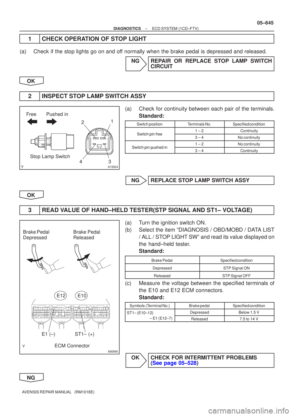
(a)Check for continuity between each pair of the terminals. Standard:
Switch positionTerminals No.Specified condition
Switchpinfree1 ± 2ContinuitySwitch pin free3 ± 4No continuity
Switchpinpushedin1 ± 2No continuitySwitch pin pushed in3 ± 4Continuity
NGREPLACE STOP LAMP SWITCH ASSY
OK
3READ VALUE OF HAND±HELD TESTER(STP SIGNAL AND ST1± VOLTAGE)
(a)Turn the ignition switch ON.
(b)Select the item ºDIAGNOSIS / OBD/MOBD / DATA LIST / ALL / STOP LIGHT SWº and read its value displayed on
the hand±held tester.
Standard:
Brake PedalSpecified condition
DepressedSTP Signal ON
ReleasedSTP Signal OFF
(c)Measure the voltage between the specified terminals ofthe E10 and E12 ECM connectors.
Standard:
Symbols (Terminal No.)Brake pedalSpecified condition
ST1± (E10±12) DepressedBelow 1.5 VST1 (E1012)
± E1 (E12±7)
Released7.5 to 14 V
OKCHECK FOR INTERMITTENT PROBLEMS (See page 05±528)
NG
Page 804 of 5135

0577T±04
F45095
ABS Warning Ligh t
BRAKE Warning
Light
C52361
Tc
CG
R01346
Norma l Code
Code 1 1 and 21
Code 11
4 sec. 0.25 sec.
2.5 sec.
1.5 sec. 0.25 sec.
2 sec.
0.5 sec . 0.5 sec.
Code 21
ON
OFF
ON
OFF
±
DIAGNOSTIC SABS WITH EBD SYSTEM
05±699
AVENSIS RE PAIR MANUAL (RM1018E)
PRE±CHECK
1. DIAGNOSI S SYSTEM
(a ) Release the parking brake leve r.
(b ) Check the warning lights.
Whe n the ignition switch is turned ON, check that the ABS
warnin g light and brake warning light come on for 3 sec.
HIN T:
�Whe n the parking brake is applied or the level of the brake
flui d is lo w, the brake warning light comes on.
�If the indicator check result is not normal, proceed to trou-
bleshootin g for the ABS warning light circuit ( See page
05±73 7 or 05±741 ) or brake warning light circuit ( See
pag e 05±744 ).
(c ) Without using hand±held tester:
Check the DTC.
(1 ) Usin g S S T, c onne ct te rmi na l T c a n d C G o f the
DLC3.
SS T 09843±18040
(2 ) Tur n the ignition switch ON.
(3 ) Rea d the DTC from the ABS warning light on the
combinatio n mete r.
HIN T:
�If no code appears, inspect the diagnostic circuit or ABS
warning light circuit ( See page 05±737 or 05±744 ).
�As an example, the blinking patterns for normal code and
code s 1 1 and 21 are shown on the left.
(4 ) Codes are explained in the code table on page
05±704.
If 2 or more DTCs are detected at the same time, the lowest
numbered DTC is displayed 1st. (5) After completing the check, remove the SST fromthe DLC3.
SST 09843±18040
(d) With using hand±held tester: Check the DTC.
(1) Read the DTC by following the prompts on the tes-ter screen.
HINT:
Please refer to the hand±held tester operator's manual for fur-
ther details.
(e) Without using hand±held tester: Clear the DTCs.
(1) Using SST, connect the terminal Tc and CG of theDLC3.
SST 09843±18040
(2) Turn the ignition switch ON.
Page 816 of 5135

0577Y±02
F45094
ABS Warning LightBRAKE Warning
Light
VSC Warning Light SLIP Indicator Light
TRC OFF Indicator
Light
C52361
DLC3 Tc
CG
05±756
±
DIAGNOSTICS ABS WITH EBD & BA & TRC & VSC SYSTEM
AVENSIS REPAIR MANUAL (RM1018E)
PRE±CHECK
1.DIAGNOSIS SYSTEM
(a)Check the warning lights. (1)Release the parking brake lever.
(2)When the ignition switch is turned ON, check thatthe ABS warning light, Brake warning light, VSC
warning light, TRC OFF indicator light and SLIP in-
dicator light come on for approx. 3 seconds.
HINT:
�When the parking brake is applied or brake fluid level is
low, the Brake warning light comes on.
�If the ECU stores DTC, the ABS warning light , VSC warn-
ing light and TRC OFF indicator light come on.
�If the indicator check result is not normal, proceed to trou-
bleshooting for the light circuit.
Trouble AreaSee page
ABS warning light circuit05±827
Brake warning light circuit05±840
VSC warning light circuit05±831
TRC OFF indicator light circuit05±844
SLIP indicator light circuit05±848
(b) Without using hand±held tester: Check the DTC.
(1) Using SST, connect terminal Tc and CG of theDLC3.
SST 09843±18040
(2) Turn the ignition switch ON.
(3) Read the DTC from the ABS warning light or VSC warning light on the combination meter.
HINT:
�If no code appears, inspect the diagnostic circuit, ABS
warning light circuit or VSC warning light circuit.
Trouble AreaSee page
Tc terminal circuit05±852
ABS warning light circuit05±827
VSC warning light circuit05±831
Page 1122 of 5135
F44861
B±W22
C11Combination Meter
Driver Side J/B
Engine Room R/B No.4 Engine Room R/B No.1 and
Engine Room J/B No.1Power Steering
ECU Assy
6
C11
17
C10B±W
W±B
W±B
B±WP/S
J8C
AM2 J26A
J8C
J26A J/C
B±WB±R
B±R B±R B±R
B±RB±GB±G
B±G (*1) (*2) (*1) (*2)(*1)
(*2)
18
DA2
DH IGN
IE41
IP11
(*1) (*2)
1
1A1
111
4A
4B
2AM2 IG2 I13
Ignition SWE159
WL
46
FL MAIN
BatteryJ15
J/CJ16
J/C
IK
IO AA
*1: LHD
*2: RHDA
AJ17
J/C
A W±B
(*2)
W±B
(*1) 05±1082
± DIAGNOSTICSELECTRONIC MOTOR POWER STEERING SYSTEM
AVENSIS REPAIR MANUAL (RM1018E)
EMPS Warning Light Circuit
CIRCUIT DESCRIPTION
If the power steering ECU assy detects a trouble, the PS warning lights up. At this time, the power steering
ECU assy records a DTC in memory.
WIRING DIAGRAM
05C5I±01
Page 1225 of 5135
050YH±19
±
DIAGNOSTICS SUPPLEMENTAL RESTRAINT SYSTEM
05±1197
AVENSIS REPAIR MANUAL (RM1018E)
PROBLEM SYMPTOMS TABLE
HINT:
Proceed the troubleshooting for each circuit in the below table.
SymptomSuspect AreaSee page
�When the ignition switch is ON, the SRS warning light some-
times come on after approx. 6 seconds.
�SRS warning light circuit malfunction
�SRS warning light is always lit up even when ignition switch is in
the LOCK position.
SRS warning light circuit malfunction
(Always lights up, when ignition switch is LOCK position).05±1386
� With the ignition switch is ON, the SRS warning light does not
come on.�SRS warning light circuit malfunction
(Does not light up, when ignition switch is turned to ON).05±1389
�DTC is not displayed.
�SRS warning light is always on at the time of DTC check proce-
dure.�TC terminal circuit05±1391
�DTC is displayed without connecting TC and CG terminal.
Page 1233 of 5135

05C5V±01
3
2
145678
910111213141516
DLC3
A04550
C93955
05±1184
±
DIAGNOSTICS SUPPLEMENTAL RESTRAINT SYSTEM
AVENSIS REPAIR MANUAL (RM1018E)
PRE±CHECK
1.DIAGNOSIS SYSTEM
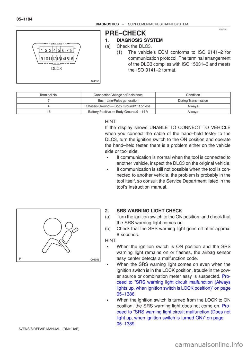
(a)Check the DLC3. (1)The vehicle's ECM conforms to ISO 9141±2 forcommunication protocol. The terminal arrangement
of the DLC3 complies with ISO 15031±3 and meets
the ISO 9141±2 format.
Terminal No.Connection/Voltage or ResistanceCondition
7Bus + Line/Pulse generationDuring Transmission
4Chassis Ground � Body Ground/1 � or lessAlways
16Battery Positive � Body Ground/9 ± 14 VAlways
HINT:
If the display shows UNABLE TO CONNECT TO VEHICLE
when you connect the cable of the hand±held tester to the
DLC3, turn the ignition switch to the ON position and operate
the hand±held tester, there is a problem either on the vehicle
side or tool side.
�If communication is normal when the tool is connected to
another vehicle, inspect the DLC3 on the original vehicle.
�If communication is still not possible when the tool is con-
nected to another vehicle, the problem is probably in the
tool itself, so consult the Service Department listed in the
tool's instruction manual.
2.SRS WARNING LIGHT CHECK
(a)Turn the ignition switch to the ON position, and check that the SRS warning light comes on.
(b)Check that the SRS warning light goes off after approx.
6 seconds.
HINT:
�When the ignition switch is ON position and the SRS
warning light remains on or flashes, the airbag sensor
assy center detects a malfunction code.
�When the SRS warning light comes on even when the
ignition switch is in the LOCK position, trouble in the pow-
er source or combination meter assy is suspected. Pro-
ceed to ºSRS warning light circuit malfunction (Always
lights up, when ignition switch is LOCK position)º on page
05±1386.
�When the ignition switch is turned from the LOCK to ON
position, the SRS warning light does not come on. Pro-
ceed to ºSRS warning light circuit malfunction (Does not
light up, when ignition switch is turned ON)º on page
05±1389.
Page 1533 of 5135
I34626
C11±14 (ILL+)
C11±1 (TURN L)
C11±13 (TURN R) C11±12 (BEAM+)
TURN±L
TURN±R TAIL IND
BEAM±
AVC±LAN
I/F
DOOR
LIGHTS
OUTSIDE TEMP
ODO/TRIP
S
T
F
W
A/T SHIFT
CLOCK
CPU POWER
SUPPLY
C11±18 (4P OUT)
C10±2 (ACC)
C11±20 (+B) C10±6 (BEAM±)
C10±3 (AVC LAN+)
C10±5 (FE) C10±4 (AVC LAN±)
C10±13 (BEAN (EFI))
C10±15 (BEAN (SECURITY))
C10±14 (BEAN (BODY)) C10±17 (POWER EARTH)
C10±12 (OUTSIDE TEMP±)
C10±11 (OUTSIDE TEMP+)
C10±10 (FUEL)
C10±16 (E/G OIL LEVEL)*1
C10±1 (WATER LEVEL)*1
C11±5 (SIGNAL EARTH)
C11±19 (SI)
C11±3 (TACHO)CPU BEAN I/F
± DIAGNOSTICSCOMBINATION METER
05±1503
AVENSIS REPAIR MANUAL (RM1018E)