Page 2063 of 5135
A76703
Fan and Generator V Belt
Cooler Compressor Assy
N´m (kgf´cm, ft´lbf) : Specified torque
29 (296, 21)
A/T:
Floor Shift Transmission
Control Cable Assy Clip
Clutch Release Cylinder Assy
Floor Shift Cable Transmission
Control Shift
Floor Shift Cable Transmission
Control Select
Clip
Clip
25 (255, 18)
12 (122, 9)
25 (255, 18)
12 (122, 9)
54 (551, 40)
25 (255, 18)
Generator Assy Terminal Cap
No. 19.8 (100, 7)
± ENGINE MECHANICALPARTIAL ENGINE ASSY (1ZZ±FE/3ZZ±FE)
14±21
AVENSIS REPAIR MANUAL (RM1018E)
Page 2072 of 5135

A77298
LHD Steering Position typeRHD Steering Position type
14±124
±
ENGINE MECHANICAL PARTIAL ENGINE ASSY(1AZ±FE)
AVENSIS REPAIR MANUAL (RM1018E)
40.REMOVE FRONT AXLE HUB RH NUT SST09330±00030
HINT:
Perform the same procedure as above on the opposite side.
41.SEPARATE TIE ROD END SUB±ASSY LH (See page 51±36)
42.SEPARATE TIE ROD END SUB±ASSY RH
HINT:
Perform the same procedure as above on the opposite side.
43.SEPARATE FRONT STABILIZER LINK ASSY LH (See page 26±26)
44.SEPARATE FRONT STABILIZER LINK ASSY RH
HINT:
Perform the same procedure as above on the opposite side.
45.SEPARATE FRONT SUSPENSION ARM SUB±ASSY LOWER NO.1 LH (M/T TRANSAXLE)
(See page 26±21)
46.SEPARATE FRONT SUSPENSION ARM SUB±ASSY LOWER NO.1 LH (A/T TRANSAXLE) (See page 26±16)
47.SEPARATE FRONT SUSPENSION ARM SUB±ASSY LOWER NO.1 RH (M/T TRANSAXLE)
HINT:
Perform the same procedure as above on the opposite side.
48.SEPARATE FRONT SUSPENSION ARM SUB±ASSY LOWER NO.1 RH (A/T TRANSAXLE)
HINT:
Perform the same procedure as above on the opposite side.
49.SEPARATE FRONT AXLE ASSY LH (See page 30±6)
50.SEPARATE FRONT AXLE ASSY RH (See page 30±6)
HINT:
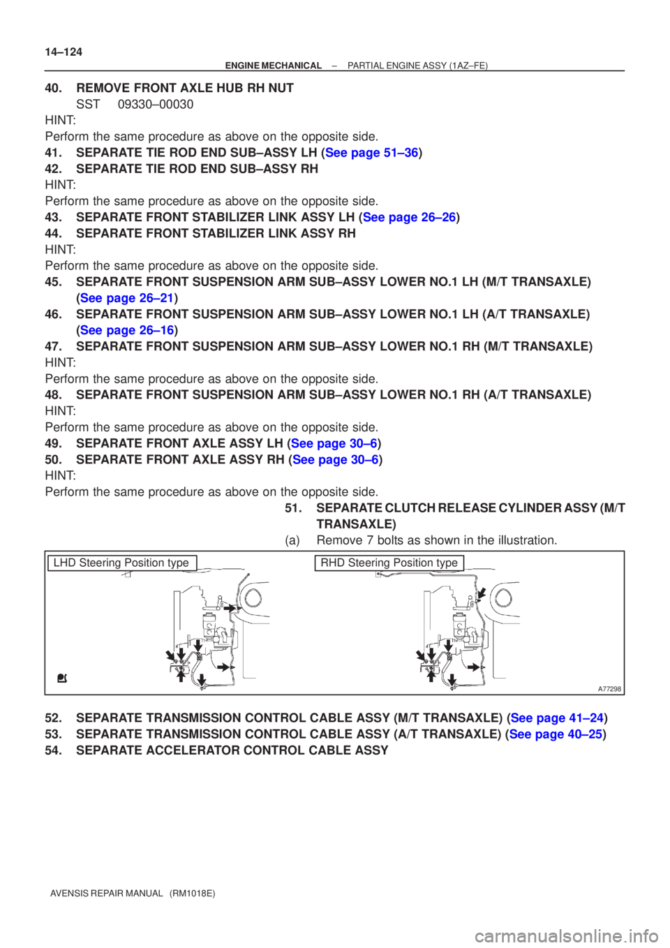
Perform the same procedure as above on the opposite side. 51.SEPARATE CLUTCH RELEASE CYLINDER ASSY (M/TTRANSAXLE)
(a)Remove 7 bolts as shown in the illustration.
52.SEPARATE TRANSMISSION CONTROL CABLE ASSY (M/T TRANSAXLE) (See page 41±24)
53.SEPARATE TRANSMISSION CONTROL CABLE ASSY (A/T TRANSAXLE) (See page 40±25)
54. SEPARATE ACCELERATOR CONTROL CABLE ASSY
Page 2080 of 5135
A77304
A77305
A77405
A
B
A
A
A77298
LHD Steering Position typeRHD Steering Position type
AB
A
A
AA
A
C
C
C
C
C
C
B
14±132
±
ENGINE MECHANICAL PARTIAL ENGINE ASSY(1AZ±FE)
AVENSIS REPAIR MANUAL (RM1018E)
120.INSTALL TRANSVERSE ENGINE ENGINE MOUNTING INSULATOR
Torque: 87 N �m (887 kgf �cm, 64 ft �lbf)
121.INSTALL TRANSVERSE ENGINE ENGINE MOUNTING INSULATOR
Torque: 52 N �m (530 kgf �cm, 38 ft �lbf)
122.INSTALL ENGINE MOUNTING BRACKET NO.2 RH Torque:
A 52 N �m (530 kgf �cm, 38 ft �lbf)
B 113 N �m (1,152 kgf �cm, 83 ft �lbf)
123.REMOVE ENGINE HANGERS
124.INSTALL STEERING INTERMEDIATE SHAFT ASSY NO.2 (See page 50±9)
125.INSTALL TRANSMISSION CONTROL CABLE ASSY (M/T TRANSAXLE) (
See page 41±24)
126.INSTALL TRANSMISSION CONTROL CABLE ASSY (A/T TRANSAXLE) (See page 40±25) 127. INSTALL CLUTCH RELEASE CYLINDER ASSY (M/TTRANSAXLE)
Torque:
Bolt A 12 N �m (122 kgf �cm, 89 ft �lbf)
Bolt B 9.0 N �m (92 kgf �cm, 79 in. �lbf)
Bolt C 5.0 N �m (51 kgf �cm, 44 in. �lbf)
Page 2087 of 5135
A77314
A/T:
Clip
Transmission
Control Cable Assy
N´m (kgf´cm, ft´lbf)
: Specified torque
M/T:
Transmission Control
Cable Assy
5.0 (51, 44 in.�lbf)
12 (120, 9.0)
M/T:
Clutch Release
Cylinder Assy
12 (122, 8.9)
Clip
5.0 (51, 44 in.�lbf)
9.0 (92, 80 in.�lbf)
± ENGINE MECHANICALPARTIAL ENGINE ASSY (1AZ±FE)
14±115
AVENSIS REPAIR MANUAL (RM1018E)
Page 2099 of 5135

140D1±02
CG
TCA51075
A52004
±
ENGINE MECHANICAL ENGINE(1AZ±FE)
14±101
AVENSIS REPAIR MANUAL (RM1018E)
ENGINE(1AZ±FE)
INSPECTION
1.INSPECT COOLANT (See page 16±13)
2.INSPECT ENGINE OIL (See page 17±6)
3. INSPECT BATTERY
Standard specific gravity: 1.25 to 1.29 at 20 �C (68 �F)
4. INSPECT AIR CLEANER FILTER ELEMENT SUB±ASSY
5.INSPECT SPARK PLUG (See page 18±9)
6. INSPECT V±RIBBED BELT
7. INSPECT IGNITION TIMING
(a) Warm up engine.
(b) When using hand±held tester:(1) Connect the hand±held tester to the DLC3.
(2) Enter DATA LIST MODE on the hand±held tester.
Ignition timing: 8 to 12 � BTDC
HINT:
Please refer to the hand±held tester operator's manual if you
need help to select DATA LIST.
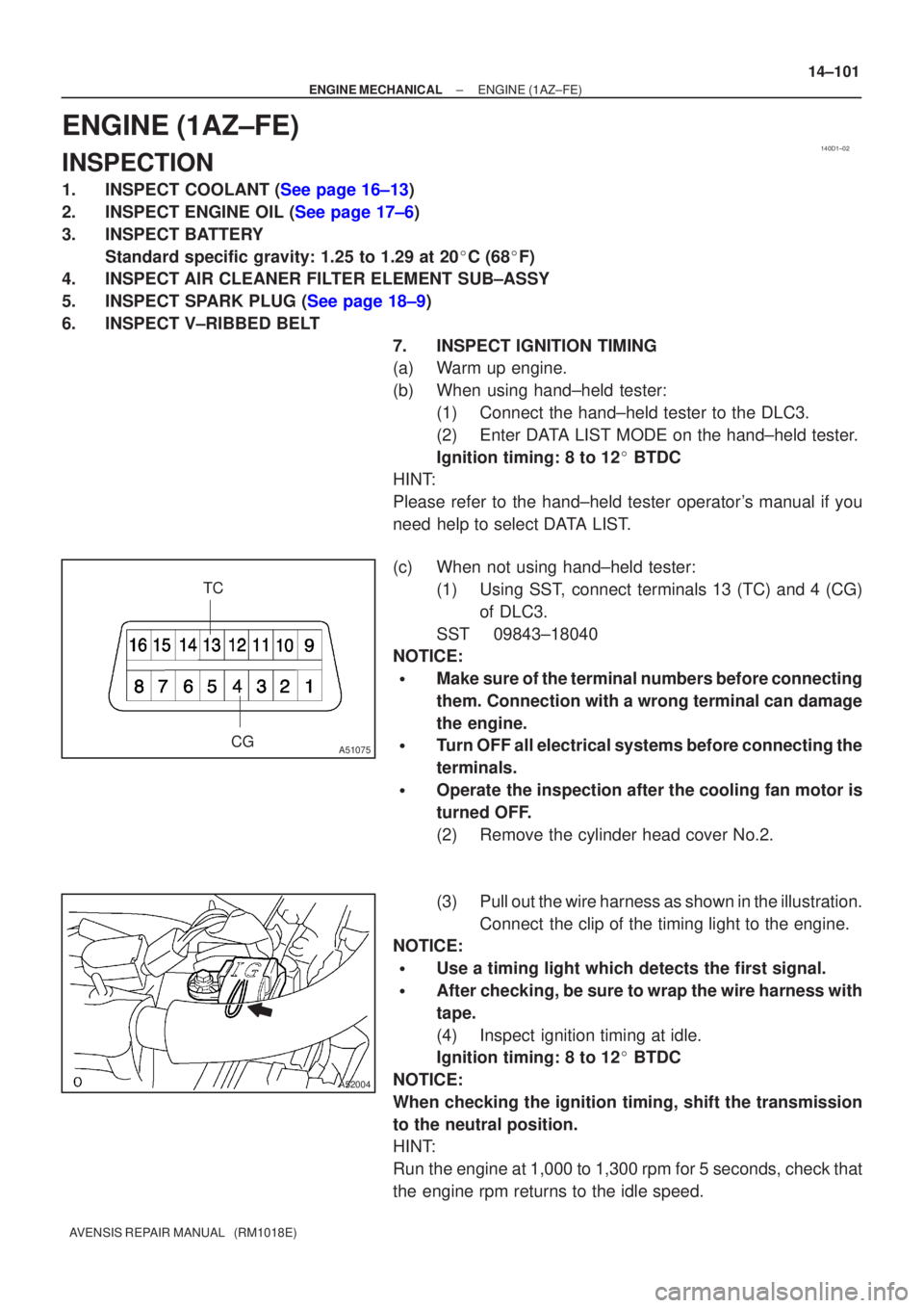
(c) When not using hand±held tester:
(1) Using SST, connect terminals 13 (TC) and 4 (CG)of DLC3.
SST 09843±18040
NOTICE:
�Make sure of the terminal numbers before connecting
them. Connection with a wrong terminal can damage
the engine.
�Turn OFF all electrical systems before connecting the
terminals.
�Operate the inspection after the cooling fan motor is
turned OFF.
(2) Remove the cylinder head cover No.2.
(3) Pull out the wire harness as shown in the illustration.
Connect the clip of the timing light to the engine.
NOTICE:
�Use a timing light which detects the first signal.
�After checking, be sure to wrap the wire harness with
tape.
(4) Inspect ignition timing at idle.
Ignition timing: 8 to 12 � BTDC
NOTICE:
When checking the ignition timing, shift the transmission
to the neutral position.
HINT:
Run the engine at 1,000 to 1,300 rpm for 5 seconds, check that
the engine rpm returns to the idle speed.
Page 2128 of 5135

141CP±01
CG
TCA51075
A79034
±
ENGINE MECHANICAL ENGINE(1AZ±FSE)
14±181
AVENSIS REPAIR MANUAL (RM1018E)
ENGINE(1AZ±FSE)
INSPECTION
1.INSPECT COOLANT (See page 16±25)
2.INSPECT ENGINE OIL(See page 17±13)
3.INSPECT BATTERY
Standard specific gravity: 1.25 to 1.29 at 20 �C (68 �F)
4.INSPECT AIR CLEANER FILTER ELEMENT SUB±ASSY
5.INSPECT SPARK PLUG (See page 18±14)
6.INSPECT V±RIBBED BELT
7.INSPECT IGNITION TIMING
(a)Warm up engine.
(b)When using hand±held tester:(1)Connect the hand±held tester to the DLC3.
(2)Enter DATA LIST MODE on the hand±held tester.
Ignition timing: 8 to 12 � BTDC
HINT:
Please refer to the hand±held tester operator's manual if you
need help to select DATA LIST.
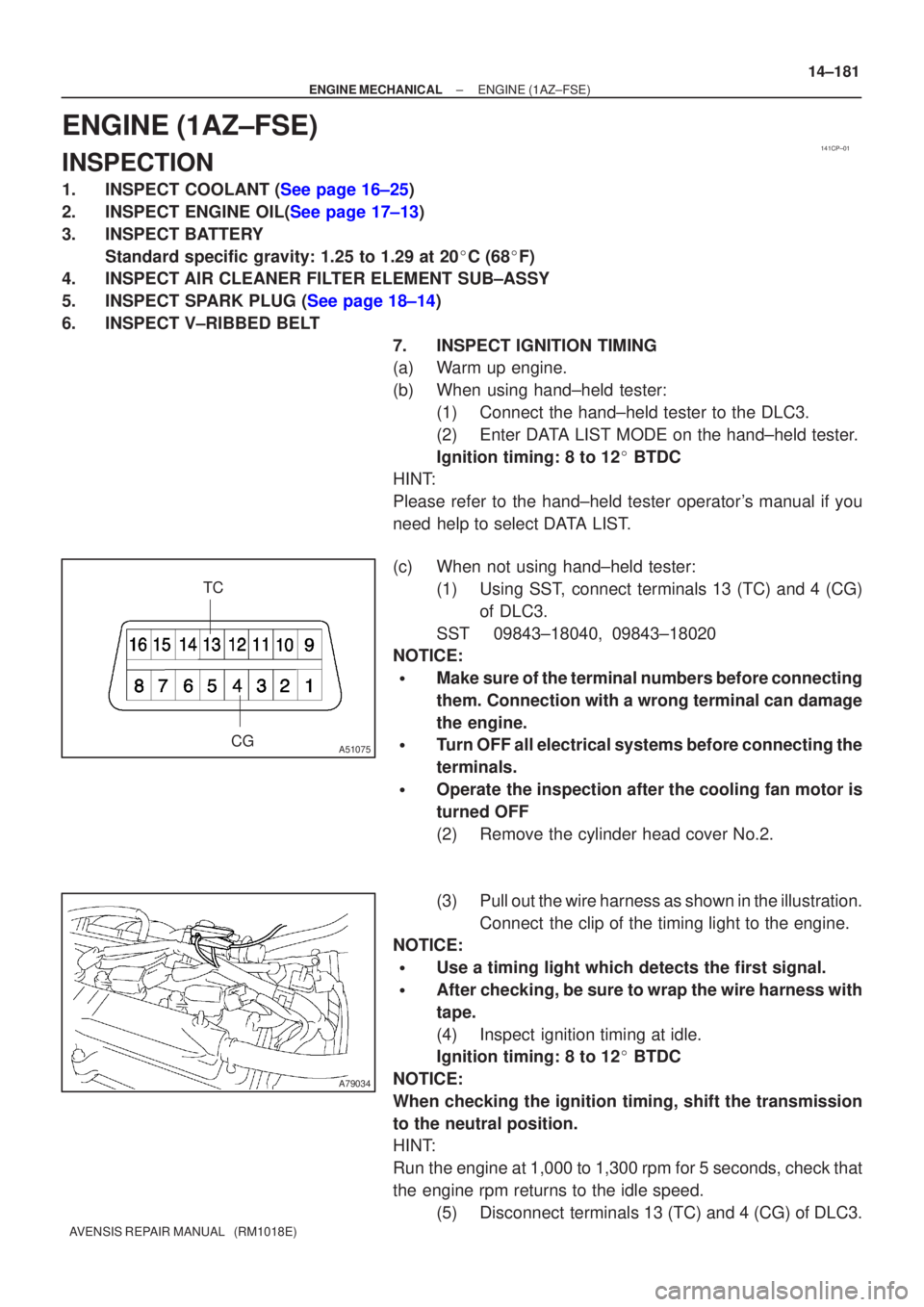
(c) When not using hand±held tester:
(1) Using SST, connect terminals 13 (TC) and 4 (CG)of DLC3.
SST 09843±18040, 09843±18020
NOTICE:
�Make sure of the terminal numbers before connecting
them. Connection with a wrong terminal can damage
the engine.
�Turn OFF all electrical systems before connecting the
terminals.
�Operate the inspection after the cooling fan motor is
turned OFF
(2) Remove the cylinder head cover No.2.
(3) Pull out the wire harness as shown in the illustration.
Connect the clip of the timing light to the engine.
NOTICE:
�Use a timing light which detects the first signal.
�After checking, be sure to wrap the wire harness with
tape.
(4) Inspect ignition timing at idle.
Ignition timing: 8 to 12 � BTDC
NOTICE:
When checking the ignition timing, shift the transmission
to the neutral position.
HINT:
Run the engine at 1,000 to 1,300 rpm for 5 seconds, check that
the engine rpm returns to the idle speed. (5) Disconnect terminals 13 (TC) and 4 (CG) of DLC3.
Page 2203 of 5135

A77298
LHD Steering Position typeRHD Steering Position type
±
ENGINE MECHANICAL PARTIAL ENGINE ASSY(1AZ±FSE)
14±207
AVENSIS REPAIR MANUAL (RM1018E)
39.REMOVE FRONT AXLE HUB RH NUT
SST09330±00030
HINT:
Perform the same procedure as above on the opposite side.
40.SEPARATE TIE ROD END SUB±ASSY LH (See page 51±36)
41.SEPARATE TIE ROD END SUB±ASSY RH
HINT:
Perform the same procedure as above on the opposite side.
42.SEPARATE FRONT STABILIZER LINK ASSY LH (See page 26±26)
43.SEPARATE FRONT STABILIZER LINK ASSY RH
HINT:
Perform the same procedure as above on the opposite side.
44.SEPARATE FRONT SUSPENSION ARM SUB±ASSY LOWER NO.1 LH (M/T TRANSAXLE)
(See page 26±21)
45.SEPARATE FRONT SUSPENSION ARM SUB±ASSY LOWER NO.1 LH (A/T TRANSAXLE) (See page 26±16)
46.SEPARATE FRONT SUSPENSION ARM SUB±ASSY LOWER NO.1 RH (M/T TRANSAXLE)
HINT:
Perform the same procedure as above on the opposite side.
47.SEPARATE FRONT SUSPENSION ARM SUB±ASSY LOWER NO.1 RH (A/T TRANSAXLE)
HINT:
Perform the same procedure as above on the opposite side.
48.SEPARATE FRONT AXLE ASSY LH (See page 30±6)
49.SEPARATE FRONT AXLE ASSY RH (See page 30±6)
HINT:
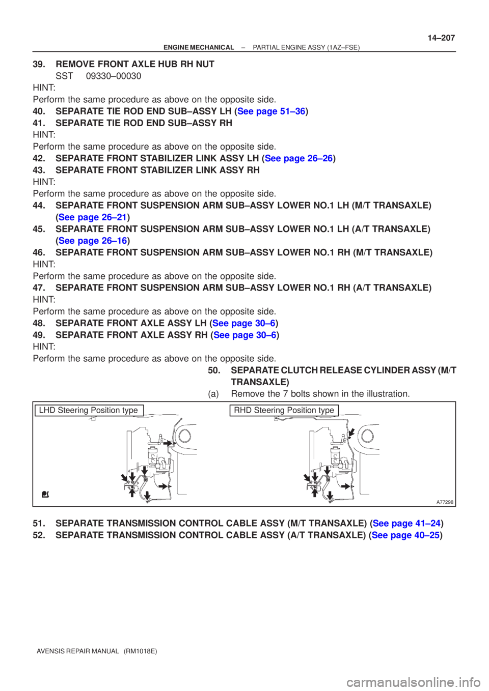
Perform the same procedure as above on the opposite side. 50.SEPARATE CLUTCH RELEASE CYLINDER ASSY (M/TTRANSAXLE)
(a)Remove the 7 bolts shown in the illustration.
51.SEPARATE TRANSMISSION CONTROL CABLE ASSY (M/T TRANSAXLE) (See page 41±24)
52.SEPARATE TRANSMISSION CONTROL CABLE ASSY (A/T TRANSAXLE) (See page 40±25)
Page 2211 of 5135
A77404
B
A
BBBB
A
B
A77304
A77305
A77405
A
B
A
A
±
ENGINE MECHANICAL PARTIAL ENGINE ASSY(1AZ±FSE)
14±215
AVENSIS REPAIR MANUAL (RM1018E)
(b)Install the front suspension member braces with the 8
bolts.
Torque:
Bolt A 133 N �m (1,356 kgf �cm, 98 ft �lbf)
Bolt B 80 N �m (816 kgf �cm, 59 ft �lbf)
132.INSTALL TRANSVERSE ENGINE ENGINE MOUNTING INSULATOR
Torque: 87 N �m (887 kgf �cm, 64 ft �lbf)
133.INSTALL TRANSVERSE ENGINE ENGINE MOUNTING INSULATOR
Torque: 52 N �m (530 kgf �cm, 38 ft �lbf)
134.INSTALL ENGINE MOUNTING BRACKET NO.2 RH Torque:
A 52 N �m (530 kgf �cm, 38 ft �lbf)
B 113 N �m (1,152 kgf �cm, 83 ft �lbf)
135.REMOVE ENGINE HANGERS
136.INSTALL STEERING INTERMEDIATE SHAFT ASSY NO.2 (See page 50±9)
137.INSTALL TRANSMISSION CONTROL CABLE ASSY (M/T TRANSAXLE) (See page 41±24)
138.INSTALL TRANSMISSION CONTROL CABLE ASSY (A/T TRANSAXLE) (See page 40±25)