Page 3477 of 5135

OVERHAUL
1. INSPECT CONNECTING ROD THRUST CLEARANCE
(a) Us")
141BU±01
A13845
A77271
Plastigage
A77272
Front Mark
± ENGINE MECHANICALCYLINDER BLOCK ASSY
14±53
1AZ±FSE ENGINE REPAIR MANUAL (RM1019E)
OVERHAUL
1. INSPECT CONNECTING ROD THRUST CLEARANCE
(a) Using a dial indicator, measure the thrust clearance while
moving the connecting rod back and forth.
Standard thrust clearance:
0.160 to 0.362 mm (0.0063 to 0.0143 in.)
Maximum thrust clearance: 0.362 mm (0.0143 in.)
(b) If the thrust clearance is greater than maximum, replace
the connecting rod assembly(s). If necessary, replace the
crankshaft.
2. INSPECT CONNECTING ROD OIL CLEARANCE
HINT:
The connecting rod cap bolts are tightened in 2 successive
steps.
(a) Check that the matchmarks on the connecting rod and
cap are aligned to ensure correct reassembly.
(b) Using a 12 mm socket wrench, remove the 2 connecting
rod cap bolts.
SST 09011±38121
(c) Clean the crank pin and bearing.
(d) Check the crank pin and bearing for pitting and scratches.
(e) Lay a strip of Plastigage on the crank pin.
(f) Check that the front mark of the connecting rod cap is fac-
ing the correct direction.
(g) Apply a light coat of engine oil on the threads of the con-
necting rod cap bolts.
(h) Using a 12 mm socket wrench, tighten the bolts in several
steps with the specified torque.
SST 09011±38121
Torque: 25 N�m (250 kgf�cm, 18 ft�lbf)
Page 3486 of 5135

(f) Exami")
A77275Front Mark and Journal Number
A77475
����
10 � � � �
A77470
90�
Engine FrontPaint
Mark
A13855
14±62
± ENGINE MECHANICALCYLINDER BLOCK ASSY
1AZ±FSE ENGINE REPAIR MANUAL (RM1019E)
(f) Examine the front marks and install the bearing caps on
the cylinder block.
(g) Apply a light coat of engine oil on the threads and under
the bearing cap bolts.
(h) Using several steps, tighten the bolts with the specified
torque in the sequence shown in the illustration.
Torque: 20 N�m (204 kgf�cm, 15 ft�lbf)
(i) Retighten the bolts in the same way as above with the
specified torque.
Torque: 40 N�m (408 kgf�cm, 29 ft�lbf)
(j) Place the front mark on each bearing cap bolt head with
paint.
(k) Retighten the bearing cap bolts by 90� in the same se-
quence as step (h).
(l) Check that each painted mark is now at a 90� angle to the
front.
NOTICE:
Do not turn the crankshaft.
(m) Remove the bearing caps.
(n) Measure the Plastigage at its widest point.
Standard oil clearance:
0.017 to 0.040 mm (0.0007 to 0.0016 in.)
Maximum oil clearance: 0.07 mm (0.0028 in.)
NOTICE:
Completely remove the Plastigage.
Page 3491 of 5135

A13501
A77275Front Mark and Journal Number
A77475
����
10 � � � �
A77470
90�
Engine FrontPaint
Mark
A77481
Claw
± ENGINE MECHANICALCYLINDER BLOCK ASSY
14±67
1AZ±FSE ENGINE REPAIR MANUAL (RM1019E)
33. INSTALL CRANKSHAFT THRUST WASHER UPPER
(a) Install the 2 thrust washers under the No. 3 journal posi-
tion of the cylinder block with the oil grooves facing out-
ward.
34. INSTALL CRANKSHAFT
(a) Apply engine oil on the upper bearing and install the
crankshaft on the cylinder block.
(b) Apply engine oil on the lower bearing.
(c) Examine the front marks and install the bearing caps to
the cylinder block.
(d) Apply a light coat of engine oil on the threads of the bear-
ing cap bolts.
(e) Using several steps, tighten the bolts with the specified
torque in the sequence shown in the illustration.
Torque: 20 N�m (204 kgf�cm, 15 ft�lbf)
(f) Retighten the bolts in the same way as above with the
specified torque.
Torque: 40 N�m (408 kgf�cm, 29 ft�lbf)
(g) Place the front mark on each bearing cap bolt head with
paint.
(h) Retighten the bearing cap bolts by 90� in the same se-
quence as step (e).
(i) Check that each painted mark is now at a 90�angle to
the front.
(j) Check that the crankshaft turns smoothly.
35. INSTALL CONNECTING ROD BEARING
(a) Align the bearing claw with the groove of the connecting
rod or connecting cap.
NOTICE:
Clean the back side of the bearing and the bearing surface
of the bearing cap and keep them free of oils.
36. INSTALL PISTON SUB±ASSY W/CONNECTING ROD
NOTICE:
The connecting rod cap bolts are tightened in 2 progres-
sive steps.
Page 3492 of 5135

(a) Apply engine oil on the cylind")
A77482
Front Mark
Front
A77483
Front Mark
A77470
90�
Engine FrontPaint
Mark 14±68
± ENGINE MECHANICALCYLINDER BLOCK ASSY
1AZ±FSE ENGINE REPAIR MANUAL (RM1019E)
(a) Apply engine oil on the cylinder walls, the pistons, and the
surfaces of connecting rod bearings.
(b) Check the position of the piston ring ends.
(c) Using a piston ring compressor, push the correctly num-
bered piston and connecting rod assemblies into each
cylinder with the front mark of the piston facing forward.
NOTICE:
Match the numbered connecting rod cap with the connect-
ing rod.
(d) Check that the protrusion of the connecting rod cap is fac-
ing the correct direction.
(e) Apply a light coat of engine oil on the threads of the con-
necting rod cap bolts.
(f) Using a 12 mm socket wrench, tighten the bolts in several
steps with the specified torque.
Torque: 25 N�m (250 kgf�cm, 18 ft�lbf)
SST 09011±38121
(g) Place the front mark on each connecting cap bolt head
with paint.
(h) Retighten the cap bolts by 90� as shown in the illustration.
(i) Check that each painted mark is at a 90� angle to the
front.
(j) Check that the crankshaft turns smoothly.
Page 3496 of 5135

8. INSPECT CYLINDER HEAD FOR CRACKS
(a) Using a dye penetrate, che")
A14180
A77457
Width
A775021.0 to 1.4mm45�
30�
± ENGINE MECHANICALCYLINDER HEAD ASSY
14±41
1AZ±FSE ENGINE REPAIR MANUAL (RM1019E)
8. INSPECT CYLINDER HEAD FOR CRACKS
(a) Using a dye penetrate, check the intake ports, exhaust
ports and cylinder surface for cracks.
9. INSPECT VALVE SEATS
(a) Apply a light coat of prussian blue (or white lead) to the
valve face.
(b) Lightly press the valve against the seat.
(c) Check the valve face and seat according to the following
procedure.
(1) If blue appears 360� around the face, the valve is
concentric. If not, replace the valve.
(2) If blue appears 360� around the valve seat, the
guide and face are concentric. If not, resurface the
seat.
(3) Check that the seat contact is in the middle of the
valve face with the width between 1.0 to 1.4 mm
(0.039 to 0.055 in.).
10. REPAIR VALVE SEATS
NOTICE:
Releasing the seat±cutter pressure gradually helps to
make smoother valve seat faces.
(a) Using a 45� cutter, cut valve face of the cylinder head a
little wider than the specified valve seating width.
(b) Confirm that the valve fits the valve seat center portion.
If not, re±cut the valve face with the 45� cutter.
(c) Adjust valve face with a 30� or 60� cutter to accurately fit
the valve seat center portion.
(1) If the seating is too high on the valve face, use 30�
and 45� cutters to correct the seat.
Page 3513 of 5135
 ISC
Idle Speed Control±
KSKnock SensorKnock Sensor
MAFMass Air FlowAir Flow Meter
MAPManifold Absolute")
± INTRODUCTIONTERMS FOR MANUAL TRANSAXLE REPAIR MANUAL
01±7
C250 M/T REPAIR MANUAL (RM1020E) ISC
Idle Speed Control±
KSKnock SensorKnock Sensor
MAFMass Air FlowAir Flow Meter
MAPManifold Absolute PressureManifold Pressure
Intake Vacuum
MCMixture Control
Electric Bleed Air Control Valve (EBCV)
Mixture Control Valve (MCV)
Electric Air Control Valve (EACV)
MDPManifold Differential Pressure±
MFIMultiport Fuel InjectionElectronic Fuel Injection (EFI)
MILMalfunction Indicator LampCheck Engine Light
MSTManifold Surface temperature±
MVZManifold Vacuum Zone±
NVRAMNon±Volatile Random Access Memory±
O2SOxygen SensorOxygen Sensor, O2 Sensor (O2S)
OBDOn±Board DiagnosticOn±Board Diagnostic (OBD)
OCOxidation Catalytic ConverterOxidation Catalyst Converter (OC), CC0
OPOpen LoopOpen Loop
PAIRPulsed Secondary Air InjectionAir Suction (AS)
PCMPowertrain Control Module±
PNPPark/Neutral Position±
PROMProgrammable Read Only Memory±
PSPPower Steering Pressure±
PTOXPeriodic Trap OxidizerDiesel Particulate Filter (DPF)
Diesel Particulate Trap (DPT)
RAMRandom Access MemoryRandom Access Memory (RAM)
RMRelay Module±
ROMRead Only MemoryRead Only Memory (ROM)
RPMEngine SpeedEngine Speed
SCSuperchargerSupercharger
SCBSupercharger Bypass±
SFISequential Multiport Fuel InjectionElectronic Fuel Injection (EFI), Sequential Injection
SPLSmoke Puff Limiter±
SRIService Reminder Indicator±
SRTSystem Readiness Test±
STScan Tool±
TBThrottle BodyThrottle Body
TBIThrottle Body Fuel InjectionSingle Point Injection
Central Fuel Injection (Ci)
TCTurbochargerTurbocharger
TCCTorque Converter ClutchTorque Converter
TCMTransmission Control ModuleTransmission ECU (Electronic Control Unit)
TPThrottle PositionThrottle Position
TRTransmission Range±
TVVThermal Vacuum ValveBimetallic Vacuum Switching Valve (BVSV)
Thermostatic Vacuum Switching Valve (TVSV)
TWCThree±Way Catalytic ConverterThree±Way Catalytic (TWC)
CC
RO
TWC+OCThree±Way + Oxidation Catalytic ConverterCCR + CCO
VA FVolume Air FlowAir Flow Meter
VRVoltage RegulatorVoltage Regulator
VSSVehicle Speed SensorVehicle Speed Sensor (Read Switch Type)
WOTWide Open ThrottleFull Throttle
Page 3710 of 5135

1AZ±FE ENGINE REPAIR MANUAL (RM865E)
CYLINDER BLOCK (1AZ±FE)
OVERHAUL
1. INSPECT CONNECTING ROD THRUST CLE")
140DW±01
A13845
A13846
A13848
A13874
14±42
± ENGINE MECHANICALCYLINDER BLOCK (1AZ±FE)
1AZ±FE ENGINE REPAIR MANUAL (RM865E)
CYLINDER BLOCK (1AZ±FE)
OVERHAUL
1. INSPECT CONNECTING ROD THRUST CLEARANCE
(a) Using a dial indicator, measure the thrust clearance while
moving the connecting rod back and forth.
Standard thrust clearance:
0.160 ± 0.362 mm (0.0063 ± 0.0143 in.)
Maximum thrust clearance: 0.362 mm (0.0143 in.)
(b) If the thrust clearance is greater than maximum, replace
the connecting rod assembly(s). If necessary, replace the
crankshaft.
2. INSPECT CONNECTING ROD OIL CLEARANCE
HINT:
The connecting rod cap bolts are tightened in 2 progressive
steps.
(a) Check the matchmarks on the connecting rod and cap are
aligned to ensure correct reassembly.
HINT:
The matchmarks on the connecting rods and caps are for en-
suring correct reassembly.
(b) Remove the 2 connecting rod cap bolts.
(c) Clean the crank pin and bearing.
(d) Check the crank pin and bearing for pitting and scratches.
(e) Lay a strip of plastigage on the crank pin.
(f) Check that the protrusion of the connecting rod cap is fac-
ing in the correct direction.
(g) Apply a light coat of engine oil on the threads and under
the heads of the connecting rod cap bolts.
(h) Tighten the bolts in several passes by the specified
torque.
Torque: 25 N�m (250 kgf�cm, 18 ft�lbf)
Page 3726 of 5135
A13874
90�
A57516
Engine FrontPaint
Mark 14±58
± ENGINE MECHANICALCYLINDER BLOCK (1AZ±FE)
1AZ±FE ENGINE REPAIR MANUAL (RM865E)
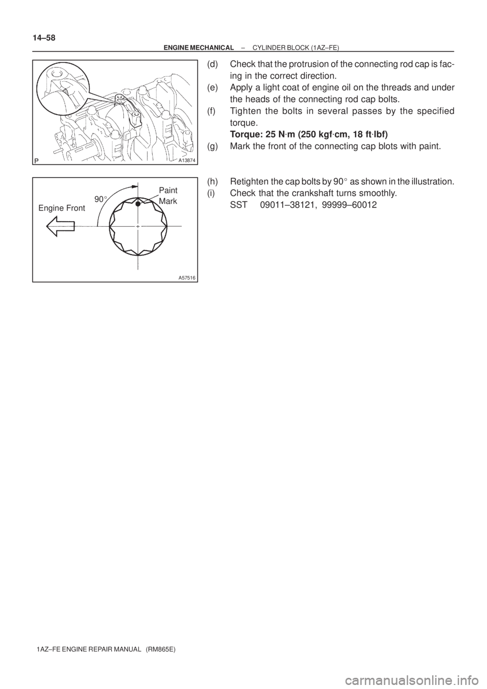
(d) Check that the protrusion of the connecting rod cap is fac-
ing in the correct direction.
(e) Apply a light coat of engine oil on the threads and under
the heads of the connecting rod cap bolts.
(f) Tighten the bolts in several passes by the specified
torque.
Torque: 25 N�m (250 kgf�cm, 18 ft�lbf)
(g) Mark the front of the connecting cap blots with paint.
(h) Retighten the cap bolts by 90� as shown in the illustration.
(i) Check that the crankshaft turns smoothly.
SST 09011±38121, 99999±60012