Page 4777 of 5135

40187−01
C91925
D30865
AT0103
C91927
40−16
− AUTOMATIC TRANSMISSION / TRANSTRANSMISSION WIRE (U151E)
AVENSIS Supplement (RM1045E)
TRANSMISSION WIRE (U151E)
REPLACEMENT
1. REMOVE ENGINE UNDER COVER LH
2. DRAIN AUTOMATIC TRANSAXLE FLUID
(a) Remove the drain plug and gasket, and drain ATF.
(b) Install a new gasket and the drain plug.
Torque: 47 N�m (479 kgf�cm, 35 ft�lbf)
3. REMOVE AUTOMATIC TRANSAXLE OIL PAN
SUB−ASSY
(a) Remove the 18 bolts, oil pan and gasket.
NOTICE:
Some fluid will remain in the oil pan. Remove all of the oil
pan bolts, and carefully remove the oil pan assembly.
(b) Remove the 2 magnets from the oil pan.
(c) Examine the particles in the oil pan.
(1) Collect any steel chips with the removed magnets.
Look at the chips and particles in the pan and on the
magnets carefully to see the type of wear which
might be found in the transaxle.
Steel (magnetic): bearing, gear and plate wear
Brass (non−magnetic): bearing wear
4. DISCONNECT TRANSMISSION WIRE
(a) Disconnect the 7 shift solenoid valve connectors.
(b) Remove the bolt and lock plate, and disconnect the ATF
temperature sensor.
Page 4850 of 5135
C91925
C86316
Magnet
AT0103
Magnet
C91927
Temperature
Sensor
D03547
Transmission Wire
40−20
− AUTOMATIC TRANSMISSION / TRANSAUTOMATIC TRANSAXLE ASSY (U151E/U151F)
U151E, U151F A/T REPAIR MANUAL (RM1021U)
9. REMOVE AUTOMATIC TRANSAXLE OIL PAN
SUB−ASSY
(a) Remove the 18 bolts, oil pan and gasket.
(b) Remove the 2 magnets from the oil pan.
10. INSPECT TRANSMISSION OIL CLEANER MAGNET
(a) Remove the magnets and use them to collect any steel
chips. Examine the chips and particles in the pan and on
the magnet to determine what type of wear has occurred
in the transaxle:
Steel (magnetic).... bearing, gear and plate wear
Brass (non−magnetic).... bushing wear
11. DISCONNECT TRANSMISSION WIRE
(a) Remove the 7 connectors from the shift solenoid valves.
(b) Remove the bolt, lock plate and ATF temperature sensor.
12. REMOVE TRANSMISSION WIRE
(a) Remove the bolt and transmission wire from the transaxle
case.
Page 4930 of 5135

054JD–22
–
DIAGNOSTICS SFI SYSTEM (1ZZ–FE/3ZZ–FE)(From February, 2004)
05–27
AVENSIS REPAIR MANUAL SUPPLEMENT
(RM1098E)
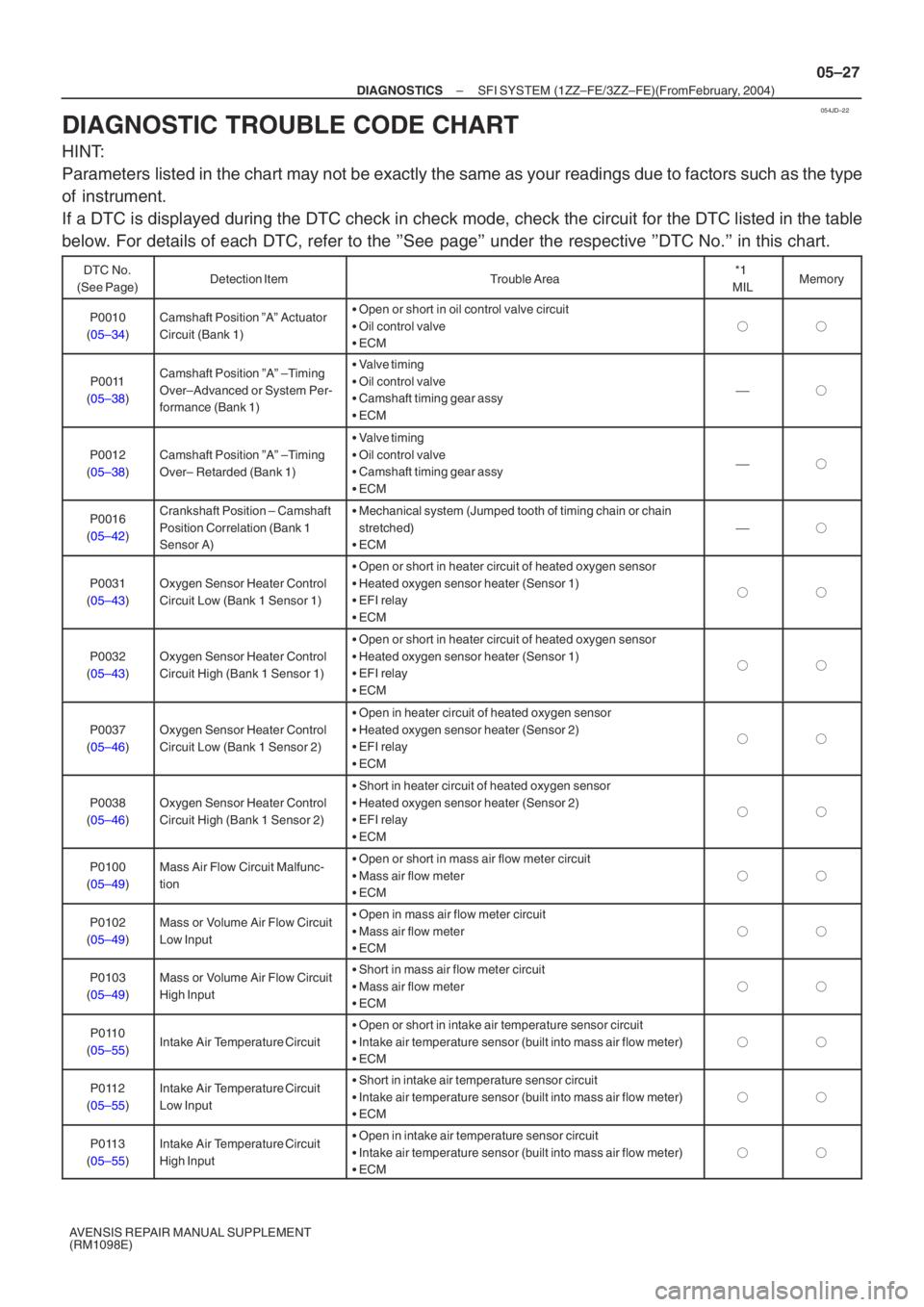
DIAGNOSTIC TROUBLE CODE CHART
HINT:
Parameters listed in the chart may not be exactly the same as your readings due to\
factors such as the type
of instrument.
If a DTC is displayed during the DTC check in check mode, check the circui\
t for the DTC listed in the table
below. For details of each DTC, refer to the ’’See page’’ under the respective ’’DTC No.’’ in this chart.
DTC No.
(See Page)Detection ItemTrouble Area*1
MILMemory
P0010
( 05–34 )Camshaft Position ”A” Actuator
Circuit (Bank 1)�Open or short in oil control valve circuit
� Oil control valve
� ECM
��
P0011
( 05–38 )Camshaft Position ”A” –Timing
Over–Advanced or System Per-
formance (Bank 1)�Valve timing
� Oil control valve
� Camshaft timing gear assy
� ECM
�
P0012
( 05–38 )Camshaft Position ”A” –Timing
Over– Retarded (Bank 1)
�Valve timing
� Oil control valve
� Camshaft timing gear assy
� ECM
�
P0016
( 05–42 )Crankshaft Position – Camshaft
Position Correlation (Bank 1
Sensor A)�Mechanical system (Jumped tooth of timing chain or chain
stretched)
� ECM
�
P0031
( 05–43 )Oxygen Sensor Heater Control
Circuit Low (Bank 1 Sensor 1)
�Open or short in heater circuit of heated oxygen sensor
� Heated oxygen sensor heater (Sensor 1)
� EFI relay
� ECM
��
P0032
( 05–43 )Oxygen Sensor Heater Control
Circuit High (Bank 1 Sensor 1)
�Open or short in heater circuit of heated oxygen sensor
� Heated oxygen sensor heater (Sensor 1)
� EFI relay
� ECM
��
P0037
( 05–46 )Oxygen Sensor Heater Control
Circuit Low (Bank 1 Sensor 2)
�Open in heater circuit of heated oxygen sensor
� Heated oxygen sensor heater (Sensor 2)
� EFI relay
� ECM
��
P0038
( 05–46 )Oxygen Sensor Heater Control
Circuit High (Bank 1 Sensor 2)
�Short in heater circuit of heated oxygen sensor
� Heated oxygen sensor heater (Sensor 2)
� EFI relay
� ECM
��
P0100
( 05–49 )Mass Air Flow Circuit Malfunc-
tion�Open or short in mass air flow meter circuit
� Mass air flow meter
� ECM
��
P0102
( 05–49 )Mass or Volume Air Flow Circuit
Low Input�Open in mass air flow meter circuit
� Mass air flow meter
� ECM
��
P0103
( 05–49 )Mass or Volume Air Flow Circuit
High Input�Short in mass air flow meter circuit
� Mass air flow meter
� ECM
��
P0110
( 05–55 )Intake Air Temperature Circuit
�Open or short in intake air temperature sensor circuit
� Intake air temperature sensor (built into mass air flow meter)
� ECM
��
P0112
( 05–55 )Intake Air Temperature Circuit
Low Input�Short in intake air temperature sensor circuit
� Intake air temperature sensor (built into mass air flow meter)
� ECM
��
P0113
( 05–55 )Intake Air Temperature Circuit
High Input�Open in intake air temperature sensor circuit
� Intake air temperature sensor (built into mass air flow meter)
� ECM
��
Page 4982 of 5135

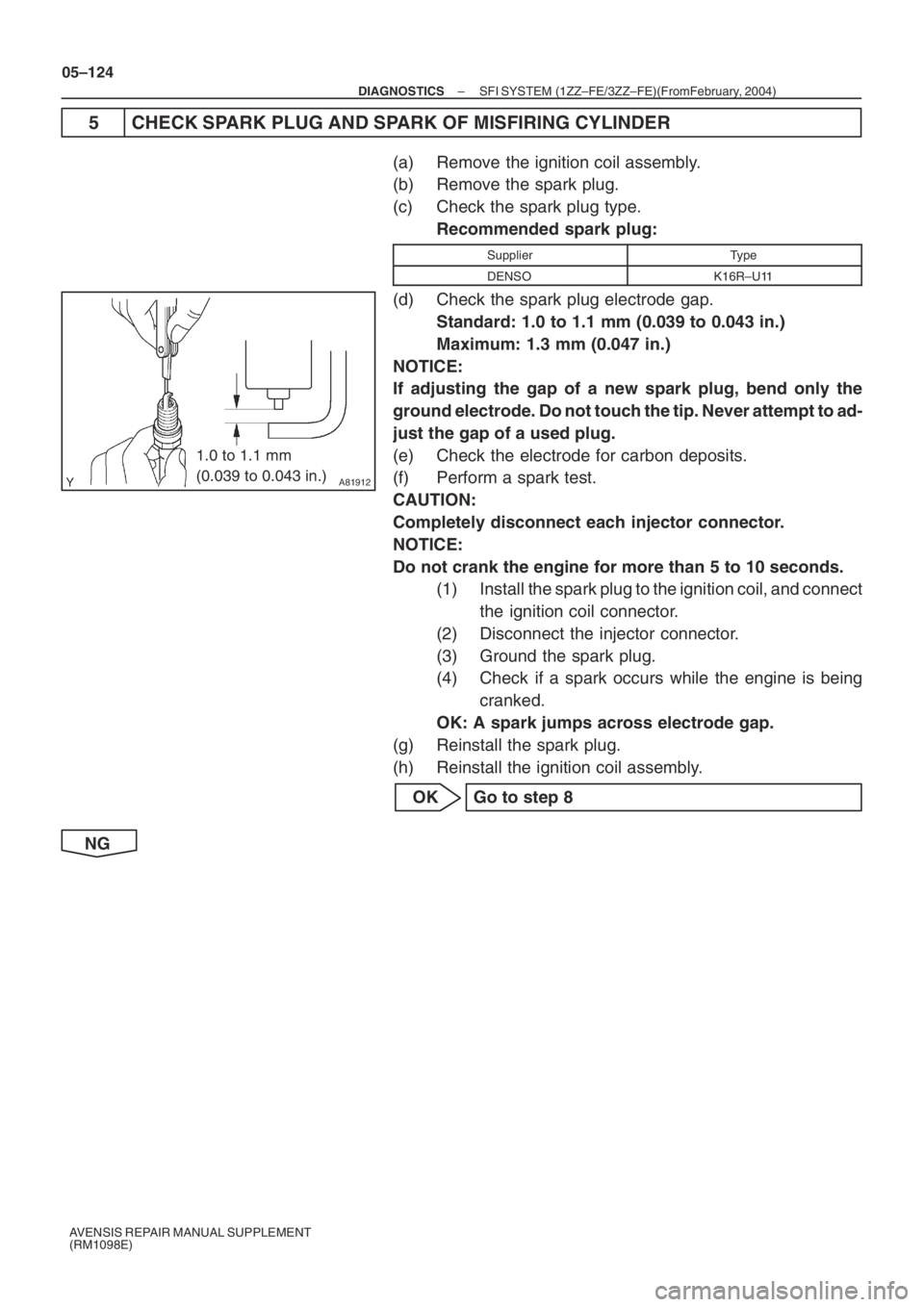
A81912
1.0 to 1.1 mm
(0.039 to 0.043 in.)
05–124
– DIAGNOSTICSSFI SYSTEM (1ZZ–FE/3ZZ–FE)(From February, 2004)
AVENSIS REPAIR MANUAL SUPPLEMENT
(RM1098E)
5 CHECK SPARK PLUG AND SPARK OF MISFIRING CYLINDER
(a) Remove the ignition coil assembly.
(b) Remove the spark plug.
(c) Check the spark plug type.
Recommended spark plug:
SupplierType
DENSOK16R–U11
(d) Check the spark plug electrode gap.
Standard: 1.0 to 1.1 mm (0.039 to 0.043 in.)
Maximum: 1.3 mm (0.047 in.)
NOTICE:
If adjusting the gap of a new spark plug, bend only the
ground electrode. Do not touch the tip. Never attempt to ad-
just the gap of a used plug.
(e) Check the electrode for carbon deposits.
(f) Perform a spark test.
CAUTION:
Completely disconnect each injector connector.
NOTICE:
Do not crank the engine for more than 5 to 10 seconds.
(1) Install the spark plug to the ignition coil, and connect
the ignition coil connector.
(2) Disconnect the injector connector.
(3) Ground the spark plug.
(4) Check if a spark occurs while the engine is being
cranked.
OK: A spark jumps across electrode gap.
(g) Reinstall the spark plug.
(h) Reinstall the ignition coil assembly.
OK Go to step 8
NG
Page 5119 of 5135

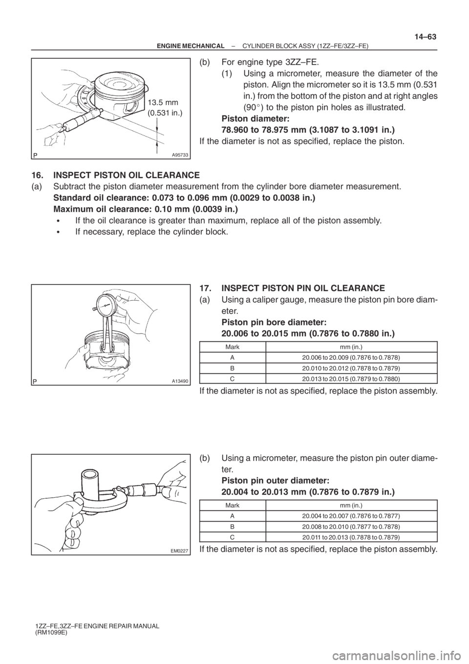
A95733
13.5 mm
(0.531 in.)
A13490
EM0227
– ENGINE MECHANICALCYLINDER BLOCK ASSY (1ZZ–FE/3ZZ–FE)
14–63
1ZZ–FE,3ZZ–FE ENGINE REPAIR MANUAL
(RM1099E)
(b) For engine type 3ZZ–FE.
(1) Using a micrometer, measure the diameter of the
piston. Align the micrometer so it is 13.5 mm (0.531
in.) from the bottom of the piston and at right angles
(90�) to the piston pin holes as illustrated.
Piston diameter:
78.960 to 78.975 mm (3.1087 to 3.1091 in.)
If the diameter is not as specified, replace the piston.
16. INSPECT PISTON OIL CLEARANCE
(a) Subtract the piston diameter measurement from the cylinder bore diameter measurement.
Standard oil clearance: 0.073 to 0.096 mm (0.0029 to 0.0038 in.)
Maximum oil clearance: 0.10 mm (0.0039 in.)
�If the oil clearance is greater than maximum, replace all of the piston assembly.
�If necessary, replace the cylinder block.
17. INSPECT PISTON PIN OIL CLEARANCE
(a) Using a caliper gauge, measure the piston pin bore diam-
eter.
Piston pin bore diameter:
20.006 to 20.015 mm (0.7876 to 0.7880 in.)
Markmm (in.)
A20.006 to 20.009 (0.7876 to 0.7878)
B20.010 to 20.012 (0.7878 to 0.7879)
C20.013 to 20.015 (0.7879 to 0.7880)
If the diameter is not as specified, replace the piston assembly.
(b) Using a micrometer, measure the piston pin outer diame-
ter.
Piston pin outer diameter:
20.004 to 20.013 mm (0.7876 to 0.7879 in.)
Markmm (in.)
A20.004 to 20.007 (0.7876 to 0.7877)
B20.008 to 20.010 (0.7877 to 0.7878)
C20.011 to 20.013 (0.7878 to 0.7879)
If the diameter is not as specified, replace the piston assembly.