Page 14 of 687
Downloaded from www.Manualslib.com manuals search engine GENERAL INFORMATION 0A-9
When disconnecting vacuum hoses, attach a tag
describing the correct installation positions so that the
hoses can be reinstalled correctly.
After servicing fuel, oil, coolant, vacuum, exhaust or
brake systems, check all lines related to the system for
leaks.
For vehicles equipped with fuel injection systems, never
disconnect the fuel line between the fuel pump and
injector without first releasing the fuel pressure, or fuel
can be sprayed out under pressure.
When performing a work that produces a heat exceeding
80°C (176°F) in the vicinity of the electrical parts, remove
the heat sensitive electrical part(s) beforehand.
Use care not to expose connectors and electrical parts
to water which will be a cause of a trouble.
Always be careful not to handle electrical parts (com-
puter, relay, etc.) in a rough manner or drop them.
Page 34 of 687

Downloaded from www.Manualslib.com manuals search engine MAINTENANCE AND LUBRICATION 0B-3
IntervalKm (x 1,000) 153045607590
Miles (x 1,000) 9 18 27 36 45 54
Months 12 24 36 48 60 72
CHASSIS AND BODY
Clutch (pedal height and travel)–I–I–I
Brake discs and pads (thickness, wear, damage) I I I I I I
Brake drums and shoes (wear, damage)–I–I–I
Brake hoses and pipes (leakage, damage, clamp)–I–I–I
Brake fluid–R–R–R
Brake lever and cable (damage, stroke, operation) Inspect at first 15,000 km (9,000 miles) only.
Tires (wear, damage, rotation) I I I I I I
Wheel discs (damage) I I I I I I
Suspension system (tightness, damage, rattle, breakage)–I–I–I
Propeller shafts––I––I
Manual transmission oil (leakage, level) (I: 1st 15,000 km only) I–R––R
Automatic transmission Fluid level–I–I–I
Fluid change Replace every 165,000 km (99,000 miles).
Fluid hose–––R––
Transfer oil (leakage, level) I–I–I–
Differential oil (leakage, level) (R: 1st 15,000 km only) R or I–I–I–
Steering system (tightness, damage, breakage, rattle)–I–I–I
Power steering (if equipped) I I I I I I
All latches, hinges and locks–I–I–I
NOTE:
“R”: Replace or change
“I”: Inspect and correct, replace or lubricate if necessary
Page 37 of 687
Downloaded from www.Manualslib.com manuals search engine 0B-6 MAINTENANCE AND LUBRICATION
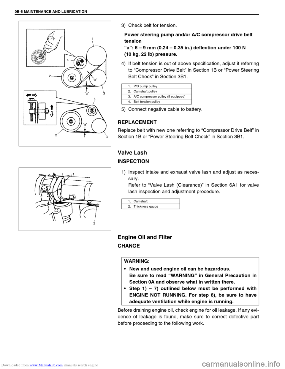
3) Check belt for tension.
Power steering pump and/or A/C compressor drive belt
tension
“a”: 6 – 9 mm (0.24 – 0.35 in.) deflection under 100 N
(10 kg, 22 lb) pressure.
4) If belt tension is out of above specification, adjust it referring
to “Compressor Drive Belt” in Section 1B or “Power Steering
Belt Check” in Section 3B1.
5) Connect negative cable to battery.
REPLACEMENT
Replace belt with new one referring to “Compressor Drive Belt” in
Section 1B or “Power Steering Belt Check” in Section 3B1.
Valve Lash
INSPECTION
1) Inspect intake and exhaust valve lash and adjust as neces-
sary.
Refer to “Valve Lash (Clearance)” in Section 6A1 for valve
lash inspection and adjustment procedure.
Engine Oil and Filter
CHANGE
Before draining engine oil, check engine for oil leakage. If any evi-
dence of leakage is found, make sure to correct defective part
before proceeding to the following work.
1. P/S pump pulley
2. Camshaft pulley
3. A/C compressor pulley (if equipped)
4. Belt tension pulley
1. Camshaft
2. Thickness gauge
WARNING:
New and used engine oil can be hazardous.
Be sure to read “WARNING” in General Precaution in
Section 0A and observe what in written there.
Step 1) – 7) outlined below must be performed with
ENGINE NOT RUNNING. For step 8), be sure to have
adequate ventilation while engine is running.
Page 39 of 687
Downloaded from www.Manualslib.com manuals search engine 0B-8 MAINTENANCE AND LUBRICATION
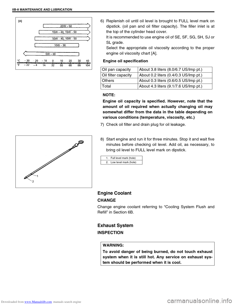
6) Replenish oil until oil level is brought to FULL level mark on
dipstick. (oil pan and oil filter capacity). The filler inlet is at
the top of the cylinder head cover.
It is recommended to use engine oil of SE, SF, SG, SH, SJ or
SL grade.
Select the appropriate oil viscosity according to the proper
engine oil viscosity chart [A].
Engine oil specification
7) Check oil filter and drain plug for oil leakage.
8) Start engine and run it for three minutes. Stop it and wait five
minutes before checking oil level. Add oil, as necessary, to
bring oil level to FULL level mark on dipstick.
Engine Coolant
CHANGE
Change engine coolant referring to “Cooling System Flush and
Refill” in Section 6B.
Exhaust System
INSPECTION
Oil pan capacity About 3.8 liters (8.0/6.7 US/lmp pt.)
Oil filter capacity About 0.2 liters (0.4/0.3 US/lmp pt.)
Others About 0.3 liters (0.6/0.5 US/lmp pt.)
Total About 4.3 liters (9.1/7.6 US/lmp pt.)
NOTE:
Engine oil capacity is specified. However, note that the
amount of oil required when actually changing oil may
somewhat differ from the data in the table depending on
various conditions (temperature, viscosity, etc.)
1. Full level mark (hole)
2. Low level mark (hole)
WARNING:
To avoid danger of being burned, do not touch exhaust
system when it is still hot. Any service on exhaust sys-
tem should be performed when it is cool.
Page 40 of 687

Downloaded from www.Manualslib.com manuals search engine MAINTENANCE AND LUBRICATION 0B-9
When carrying out periodic maintenance, or the vehicle is raised
for other service, check exhaust system as follows:
Check rubber mountings for damage, deterioration, and out
of position.
Check exhaust system for leakage, loose connections, dents
and damages.
If bolts or nuts are loose, tighten them to specification.
Check nearby body areas for damaged, missing, or misposi-
tioned parts, open seams, holes, loose connections or other
defects which could permit exhaust fumes to seep into the
vehicle.
Make sure that exhaust system components have enough
clearance from the underbody to avoid overheating and pos-
sible damage to the floor carpet.
Any defects should be fixed at once.
Ignition System
Spark Plugs
REPLACEMENT
Replace spark plugs with new ones referring to “Spark Plug” in
Section 6F.
Fuel System
Air Cleaner Filter
INSPECTION
1) Remove air cleaner case clamps (1).
2) Take cleaner filter out of air cleaner case.
3) Check air cleaner filter for dirt. Replace excessively dirty fil-
ter.
4) Blow off dust by compressed air from air outlet side of filter.
5) Install air cleaner filter into case.
6) Install air cleaner case cap and clamp it securely.
Page 41 of 687
Downloaded from www.Manualslib.com manuals search engine 0B-10 MAINTENANCE AND LUBRICATION
REPLACEMENT
Replace air cleaner filter with new one according to steps 1), 2)
and 5), 6) of inspection procedure.
Fuel Lines and Connections
INSPECTION
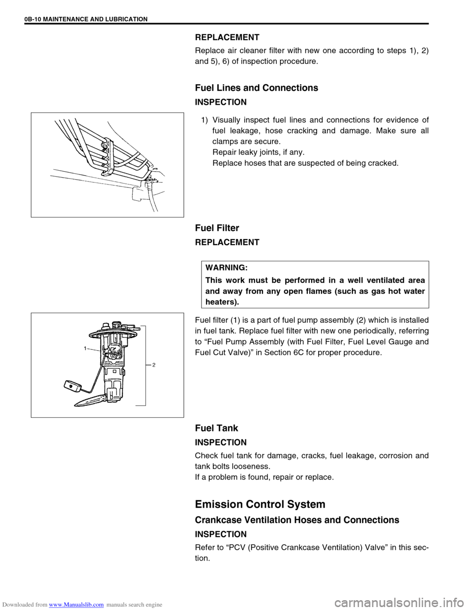
1) Visually inspect fuel lines and connections for evidence of
fuel leakage, hose cracking and damage. Make sure all
clamps are secure.
Repair leaky joints, if any.
Replace hoses that are suspected of being cracked.
Fuel Filter
REPLACEMENT
Fuel filter (1) is a part of fuel pump assembly (2) which is installed
in fuel tank. Replace fuel filter with new one periodically, referring
to “Fuel Pump Assembly (with Fuel Filter, Fuel Level Gauge and
Fuel Cut Valve)” in Section 6C for proper procedure.
Fuel Tank
INSPECTION
Check fuel tank for damage, cracks, fuel leakage, corrosion and
tank bolts looseness.
If a problem is found, repair or replace.
Emission Control System
Crankcase Ventilation Hoses and Connections
INSPECTION
Refer to “PCV (Positive Crankcase Ventilation) Valve” in this sec-
tion.
WARNING:
This work must be performed in a well ventilated area
and away from any open flames (such as gas hot water
heaters).
Page 42 of 687
Downloaded from www.Manualslib.com manuals search engine MAINTENANCE AND LUBRICATION 0B-11
PCV (Positive Crankcase Ventilation) Valve
INSPECTION
Check crankcase ventilation hose and PCV hose for leaks, cracks
or clog, and PCV valve for stick or clog. Refer to “PCV System” of
Section 6E for PCV valve checking procedure.
Fuel Evaporative Emission Control System
INSPECTION
1) Visually inspect hoses for cracks, damage, or excessive
bends. Inspect all clamps for damage and proper position.
2) Check EVAP canister for operation and clog, referring to
“Evaporative Emission (EVAP) Control System” in Section
6E.
If a malfunction is found, repair or replace.
Chassis and Body
Clutch
INSPECTION
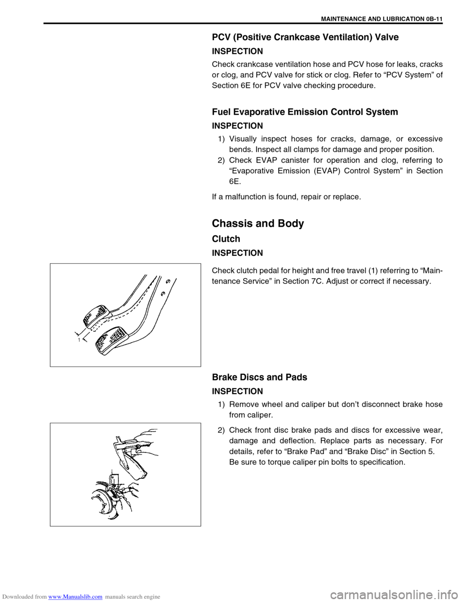
Check clutch pedal for height and free travel (1) referring to “Main-
tenance Service” in Section 7C. Adjust or correct if necessary.
Brake Discs and Pads
INSPECTION
1) Remove wheel and caliper but don’t disconnect brake hose
from caliper.
2) Check front disc brake pads and discs for excessive wear,
damage and deflection. Replace parts as necessary. For
details, refer to “Brake Pad” and “Brake Disc” in Section 5.
Be sure to torque caliper pin bolts to specification.
Page 43 of 687
Downloaded from www.Manualslib.com manuals search engine 0B-12 MAINTENANCE AND LUBRICATION
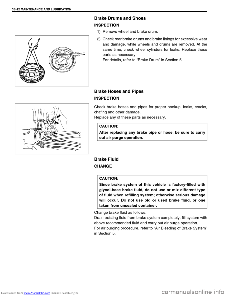
Brake Drums and Shoes
INSPECTION
1) Remove wheel and brake drum.
2) Check rear brake drums and brake linings for excessive wear
and damage, while wheels and drums are removed. At the
same time, check wheel cylinders for leaks. Replace these
parts as necessary.
For details, refer to “Brake Drum” in Section 5.
Brake Hoses and Pipes
INSPECTION
Check brake hoses and pipes for proper hookup, leaks, cracks,
chafing and other damage.
Replace any of these parts as necessary.
Brake Fluid
CHANGE
Change brake fluid as follows.
Drain existing fluid from brake system completely, fill system with
above recommended fluid and carry out air purge operation.
For air purging procedure, refer to “Air Bleeding of Brake System”
in Section 5.
CAUTION:
After replacing any brake pipe or hose, be sure to carry
out air purge operation.
CAUTION:
Since brake system of this vehicle is factory-filled with
glycol-base brake fluid, do not use or mix different type
of fluid when refilling system; otherwise serious damage
will occur. Do not use old or used brake fluid, or one
taken from unsealed container.