Page 193 of 687

Downloaded from www.Manualslib.com manuals search engine 3D-20 FRONT SUSPENSION
4) Support front axle housing by using floor jack.
5) Remove shock absorber lower mounting bolt (1).
6) Lower front axle housing (2) gradually as far down as where
coil spring (1) can be removed.
7) Remove coil spring (1).
INSTALLATION
Install removed parts in reverse order of removal procedures, not-
ing the followings.
1) Install coil spring (3).
2) Install absorber lower mounting bolt, refer to “Front Shock
Absorber” in this section.
3) Install caliper assembly and tighten caliper bolts to specified
torque.
Tightening torque
Brake caliper carrier bolts
(a) : 85 N·m (8.5 kg-m, 61.5 lb-ft)
4) Connect stabilizer ball joint to axle housing and tighten nut
referring to “Stabilizer Bar” in this section for tightening
torque specification. NOTE:
When supporting axle housing, it should be in non-load
condition.
NOTE:
Make sure that coil spring direction as shown.
When seating coil spring, mate spring end with
stepped part (4) of lower spring seat (2).
1. Front axle housing
U : Upper side
A : Small
B : Large
Page 194 of 687

Downloaded from www.Manualslib.com manuals search engine FRONT SUSPENSION 3D-21
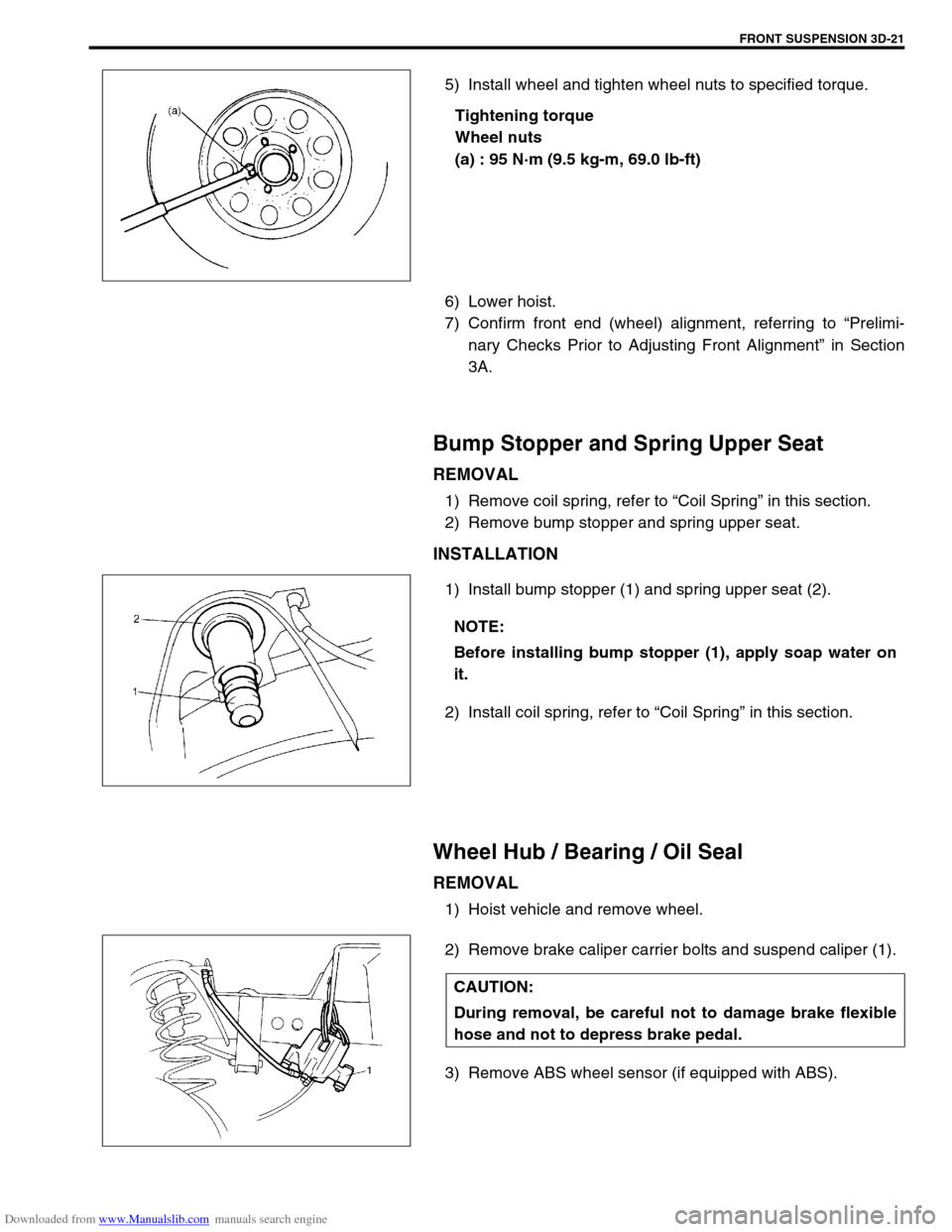
5) Install wheel and tighten wheel nuts to specified torque.
Tightening torque
Wheel nuts
(a) : 95 N·m (9.5 kg-m, 69.0 lb-ft)
6) Lower hoist.
7) Confirm front end (wheel) alignment, referring to “Prelimi-
nary Checks Prior to Adjusting Front Alignment” in Section
3A.
Bump Stopper and Spring Upper Seat
REMOVAL
1) Remove coil spring, refer to “Coil Spring” in this section.
2) Remove bump stopper and spring upper seat.
INSTALLATION
1) Install bump stopper (1) and spring upper seat (2).
2) Install coil spring, refer to “Coil Spring” in this section.
Wheel Hub / Bearing / Oil Seal
REMOVAL
1) Hoist vehicle and remove wheel.
2) Remove brake caliper carrier bolts and suspend caliper (1).
3) Remove ABS wheel sensor (if equipped with ABS).
NOTE:
Before installing bump stopper (1), apply soap water on
it.
CAUTION:
During removal, be careful not to damage brake flexible
hose and not to depress brake pedal.
Page 238 of 687

Downloaded from www.Manualslib.com manuals search engine REAR SUSPENSION 3E-19
10) Loosen rear mounting nuts of trailing arm (2) but don’t
remove bolt.
11) Remove shock absorber (1) lower mounting bolt.
12) Lower floor jack until tension of suspension coil spring
becomes a little loose and remove rear mount bolts of trailing
arm.
13) Lower rear axle housing gradually.
14) Remove axle housing.
INSTALLATION
Install removed parts in reverse order of removal, noting the fol-
lowing.
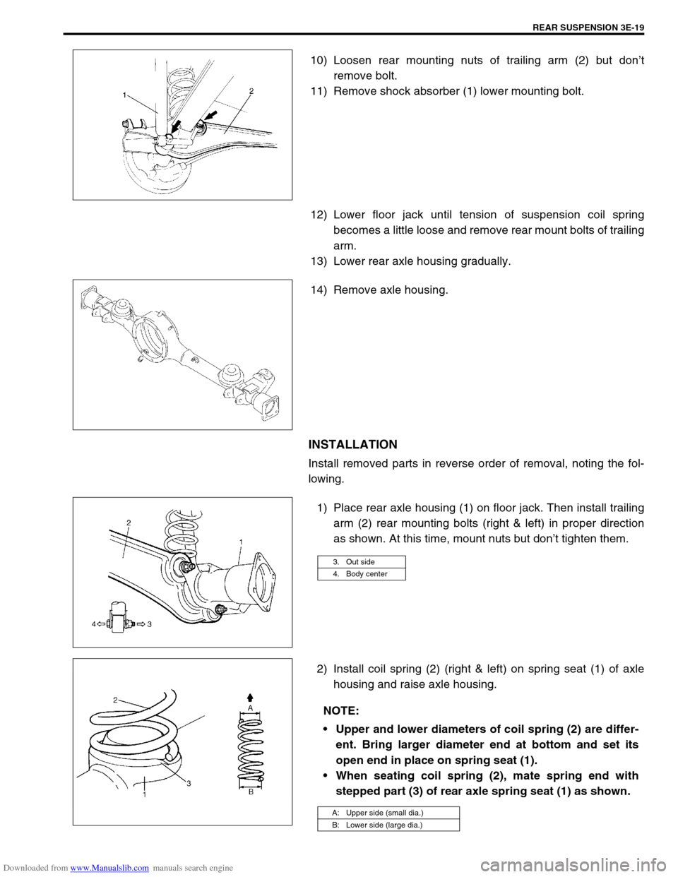
1) Place rear axle housing (1) on floor jack. Then install trailing
arm (2) rear mounting bolts (right & left) in proper direction
as shown. At this time, mount nuts but don’t tighten them.
2) Install coil spring (2) (right & left) on spring seat (1) of axle
housing and raise axle housing.
3. Out side
4. Body center
NOTE:
Upper and lower diameters of coil spring (2) are differ-
ent. Bring larger diameter end at bottom and set its
open end in place on spring seat (1).
When seating coil spring (2), mate spring end with
stepped part (3) of rear axle spring seat (1) as shown.
A: Upper side (small dia.)
B: Lower side (large dia.)
Page 298 of 687

Downloaded from www.Manualslib.com manuals search engine BRAKES 5-37
INSTALLATION
1) When using new grommets, lubricate them with the same
fluid as the one to fill reservoir with. Then press-fit grommets
to master cylinder. Grommets must be seated in place.
2) Install reservoir (1) and drive in reservoir pin (2).
3) Connect reservoir lead wire.
4) Fill reservoir (1) with specified fluid.
5) Upon completion of installation, check for fluid leakage.
Master Cylinder Assembly
REMOVAL
1) Disconnect reservoir lead wire at coupler.
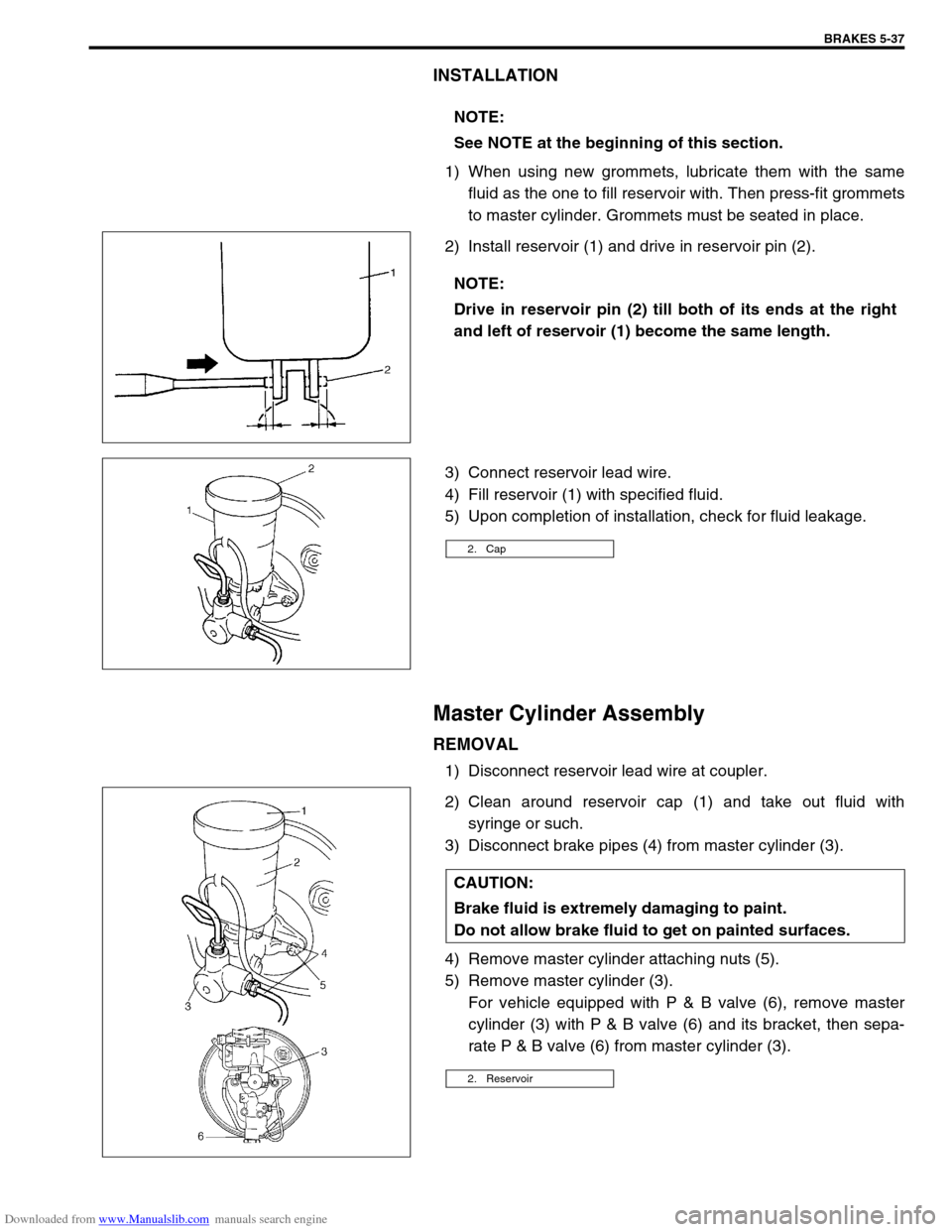
2) Clean around reservoir cap (1) and take out fluid with
syringe or such.
3) Disconnect brake pipes (4) from master cylinder (3).
4) Remove master cylinder attaching nuts (5).
5) Remove master cylinder (3).
For vehicle equipped with P & B valve (6), remove master
cylinder (3) with P & B valve (6) and its bracket, then sepa-
rate P & B valve (6) from master cylinder (3). NOTE:
See NOTE at the beginning of this section.
NOTE:
Drive in reservoir pin (2) till both of its ends at the right
and left of reservoir (1) become the same length.
2. Cap
CAUTION:
Brake fluid is extremely damaging to paint.
Do not allow brake fluid to get on painted surfaces.
2. Reservoir
Page 644 of 687

Downloaded from www.Manualslib.com manuals search engine ENGINE AND EMISSION CONTROL SYSTEM 6E-39
REMOVAL
1) Disconnect negative cable at battery.
2) Disconnect EGR valve connector.
3) Remove EGR pipe.
4) Remove EGR valve and gasket from cylinder head.
INSPECTION
1) Check resistance between following terminals of EGR valve
(1) in each pair.
If found faulty, replace EGR valve assembly.
EGR valve resistance
2) Remove carbon from EGR valve (1) gas passage.
3) Inspect valve (2), valve seat (3) and rod for fault, cracks,
bend or other damage.
If found faulty, replace EGR valve assembly.
INSTALLATION
Reverse removal procedure noting following.
Clean mating surface of valve and cylinder head.
Use new gaskets.
Evaporative emission (EVAP) control system
EVAP CANISTER PURGE INSPECTION
Terminal Standard resistance
A – B
C – B
F – E
D – E 20 – 24
Ω
ΩΩ Ω
NOTE:
Do not use any sharp-edged tool to remove carbon.
Be careful not to damage or bend EGR valve, valve seat
and rod.
NOTE:
Before inspection, check to make sure that gear shift
lever is in neutral position (with A/T model, selector lever
in “P” range) and that parking brake lever is pulled all the
way up.