2005 SUZUKI JIMNY wheel torque
[x] Cancel search: wheel torquePage 27 of 687

Downloaded from www.Manualslib.com manuals search engine 0A-22 GENERAL INFORMATION
LLH
LSPVLeft Hand
Load Sensing Proportioning Valve
TTBI
TCC
TCM
TP Sensor
TVV
TWC
2WDThrottle Body Fuel Injection
(Single-Point Fuel Injection, SPI)
Torque Converter Clutch
Transmission Control Module
(A/T Controller, A/T Control Mod-
ule)
Throttle Position Sensor
Thermal Vacuum Valve
(Thermal Vacuum Switching Valve,
TVSV, Bimetal Vacuum Switching
Valve, BVSV)
Three Way Catalytic Converter
(Three Way Catalyst)
2 Wheel Drive MMAF Sensor
MAP Sensor
Max
MFI
Min
MIL
M/TMass Air Flow Sensor
(Air Flow Sensor, AFS, Air Flow
Meter, AFM)
Manifold Absolute Pressure
Sensor (Pressure Sensor, PS)
Maximum
Multiport Fuel Injection
(Multipoint Fuel Injection)
Minimum
Malfunction Indicator Lamp
(“CHECK ENGINE” Light)
Manual Transmission
N NOx Nitrogen Oxides VVIN
VSSVehicle Identification Number
Vehicle Speed Sensor
OOBD
O/D
OHCOn-Board Diagnostic System
(Self-Diagnosis Function)
Overdrive
Over Head CamshaftWWU-OC
WU-TWCWarm Up Oxidation Catalytic
Converter
Warm Up Three Way Catalytic
Converter
PPNP
P/S
PSP Switch
PCM
PCVPark/Neutral Position
Power Steering
Power Steering Pressure Switch
(P/S Pressure Switch)
Powertrain Control Module
Positive Crankcase Ventilation
R RH Right Hand
SSAE
SDM
SFI
SOHCSociety of Automotive Engineers
Sensing and Diagnostic Module
(Air bag controller, Air bag control
module)
Sequential Multiport Fuel Injection
Single Over Head Camshaft
Page 35 of 687

Downloaded from www.Manualslib.com manuals search engine 0B-4 MAINTENANCE AND LUBRICATION
Maintenance Recommended Under Severe Driving Conditions
If the vehicle is usually used under the conditions corresponding to any severe condition code given below, it is
recommended that applicable maintenance operation be performed at the particular interval as shown in the fol-
lowing table.
Severe condition code
A : Repeated short trips
B : Driving on rough and/or muddy roads
C : Driving on dusty roads
D : Driving in extremely cold weather and/or salted roads
E : Repeated short trips in extremely cold weather
F : Leaded fuel use
G : – – – – –
H : Trailer towing (if admitted)
Severe
Condition CodeMaintenanceMaintenance
OperationMaintenance Interval
– B C D – – – –Drive belt (V-rib belt)IEvery 15,000 km
(9,000 miles) or 12 months
REvery 45,000 km
(27,000 miles) or 36 months
A – C D E F – H Engine oil and oil filter R Every 5,000 km (3,000 miles) or 4 months
– B – – – – – –Exhaust pipe mountings IEvery 15,000 km
(9,000 miles) or 12 months
– – C – – – – –Air cleaner filter ✱1I Every 2,500 km (1,500 miles)
REvery 30,000 km
(18,000 miles) or 24 months
A B C – E F – H Spark plugsNickel spark plug R Every 10,000 km (6,000 miles) or 8 months
Iridium spark plug
REvery 30,000 km
(18,000 miles) or 24 months
– B C D – – – H Wheel bearing IEvery 15,000 km
(9,000 miles) or 12 months
– B – – – – – –Suspension bolts and nuts TEvery 15,000 km
(9,000 miles) or 12 months
– B – D E – – H Propeller shafts IEvery 15,000 km
(9,000 miles) or 12 months
– B – – E – – HManual transmission,
transfer and differential oilRFirst time only:
15,000 km (9,000 miles) or 12 months
Second time and after: Every 30,000 km
(18,000 miles) or 24 months reckoning from
0 km (0 mile) or 0 month
– B – – E – – H Automatic transmission fluid REvery 30,000 km
(18,000 miles) or 24 months
– B C D – – – –Steering knuckle seal IEvery 15,000 km
(9,000 miles) or 12 months
NOTE:
“I”: Inspect and correct, replace or lubricate if necessary
“R”: Replace or change
“T”: Tighten to the specified torque
✱
✱✱ ✱1: Inspect or replace more frequently if necessary
Page 42 of 687

Downloaded from www.Manualslib.com manuals search engine MAINTENANCE AND LUBRICATION 0B-11
PCV (Positive Crankcase Ventilation) Valve
INSPECTION
Check crankcase ventilation hose and PCV hose for leaks, cracks
or clog, and PCV valve for stick or clog. Refer to “PCV System” of
Section 6E for PCV valve checking procedure.
Fuel Evaporative Emission Control System
INSPECTION
1) Visually inspect hoses for cracks, damage, or excessive
bends. Inspect all clamps for damage and proper position.
2) Check EVAP canister for operation and clog, referring to
“Evaporative Emission (EVAP) Control System” in Section
6E.
If a malfunction is found, repair or replace.
Chassis and Body
Clutch
INSPECTION
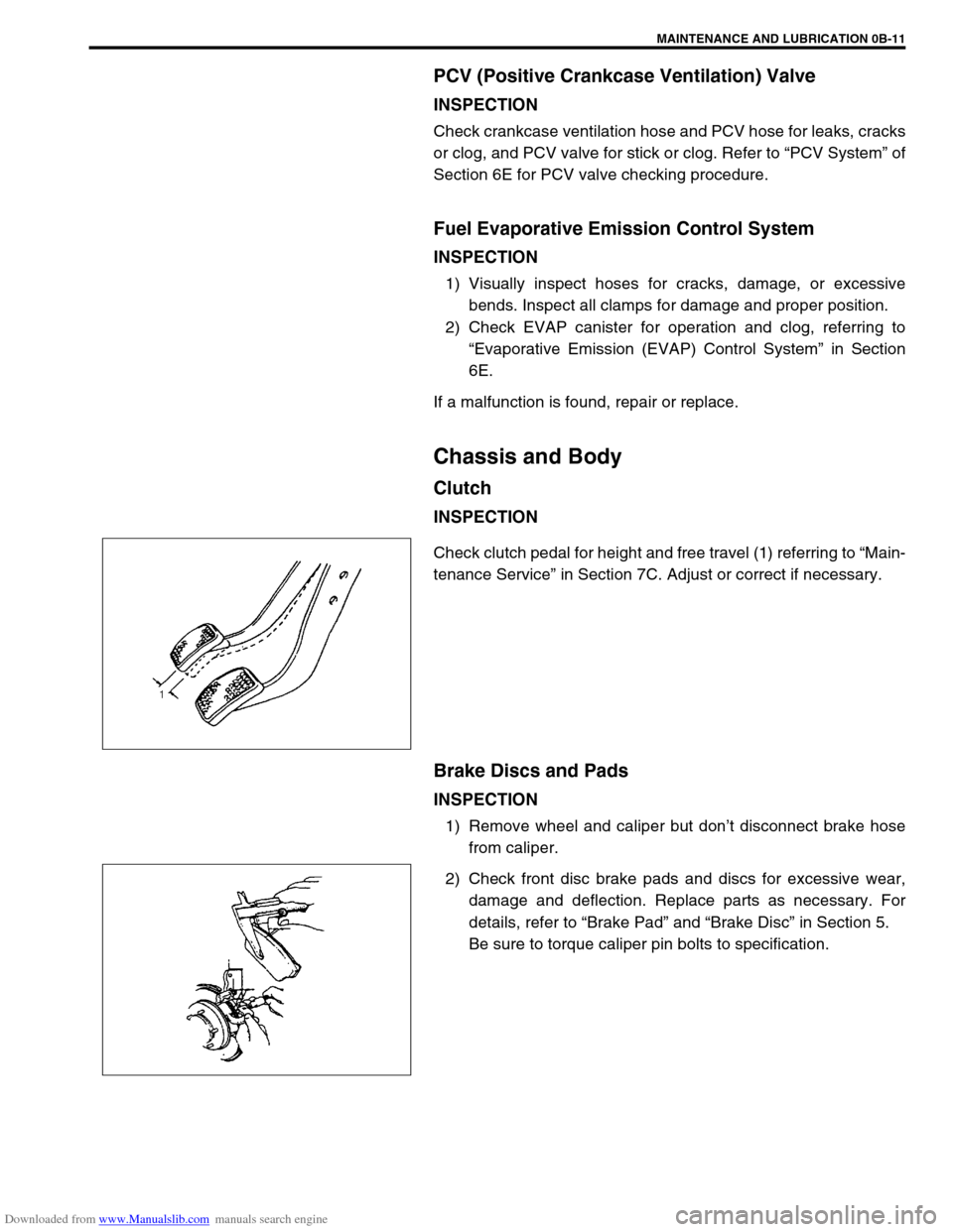
Check clutch pedal for height and free travel (1) referring to “Main-
tenance Service” in Section 7C. Adjust or correct if necessary.
Brake Discs and Pads
INSPECTION
1) Remove wheel and caliper but don’t disconnect brake hose
from caliper.
2) Check front disc brake pads and discs for excessive wear,
damage and deflection. Replace parts as necessary. For
details, refer to “Brake Pad” and “Brake Disc” in Section 5.
Be sure to torque caliper pin bolts to specification.
Page 45 of 687

Downloaded from www.Manualslib.com manuals search engine 0B-14 MAINTENANCE AND LUBRICATION
3) Rotate tires.
For details, refer to “Tire Rotation” in Section 3F.
WHEEL DISCS INSPECTION
Inspect each wheel disc for dents, distortion and cracks. A disc in
badly damaged condition must be replaced.
WHEEL BEARING INSPECTION
1) Check front wheel bearing for wear, damage, abnormal
noise or rattles. For details, refer to “Wheel Disc, Nut and
Bearing Check” in Section 3D.
2) Check rear wheel bearing for wear, damage, abnormal noise
or rattles. For details, refer to “Wheel Disc, Nut and Bearing
Check” in Section 3E.
Suspension System
INSPECTION
Check suspension bolts and nuts for tightness and retighten them
as necessary.
Repair or replace defective parts, if any.
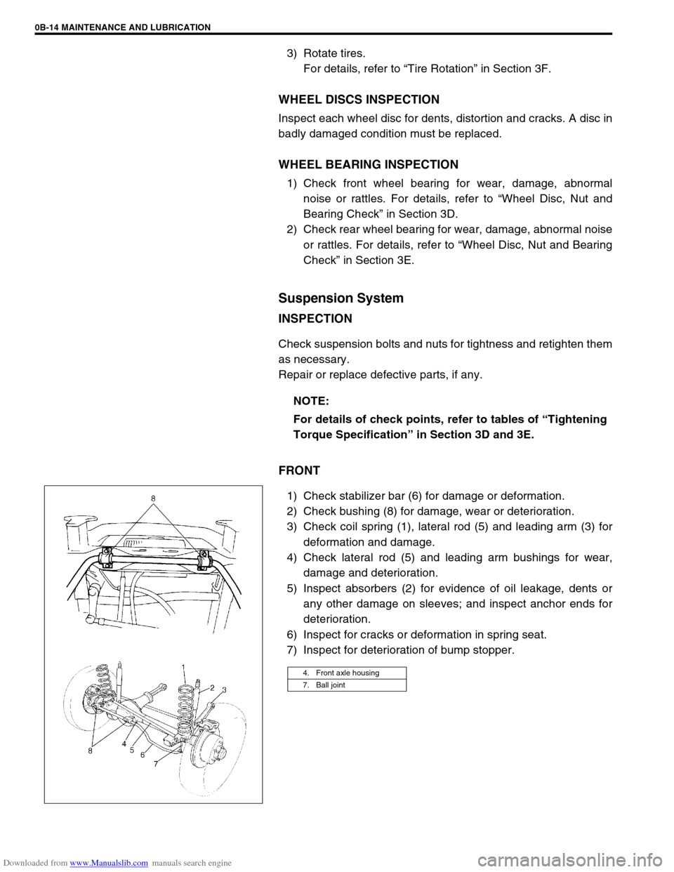
FRONT
1) Check stabilizer bar (6) for damage or deformation.
2) Check bushing (8) for damage, wear or deterioration.
3) Check coil spring (1), lateral rod (5) and leading arm (3) for
deformation and damage.
4) Check lateral rod (5) and leading arm bushings for wear,
damage and deterioration.
5) Inspect absorbers (2) for evidence of oil leakage, dents or
any other damage on sleeves; and inspect anchor ends for
deterioration.
6) Inspect for cracks or deformation in spring seat.
7) Inspect for deterioration of bump stopper.NOTE:
For details of check points, refer to tables of “Tightening
Torque Specification” in Section 3D and 3E.
4. Front axle housing
7. Ball joint
Page 49 of 687

Downloaded from www.Manualslib.com manuals search engine 0B-18 MAINTENANCE AND LUBRICATION
Steering System
INSPECTION
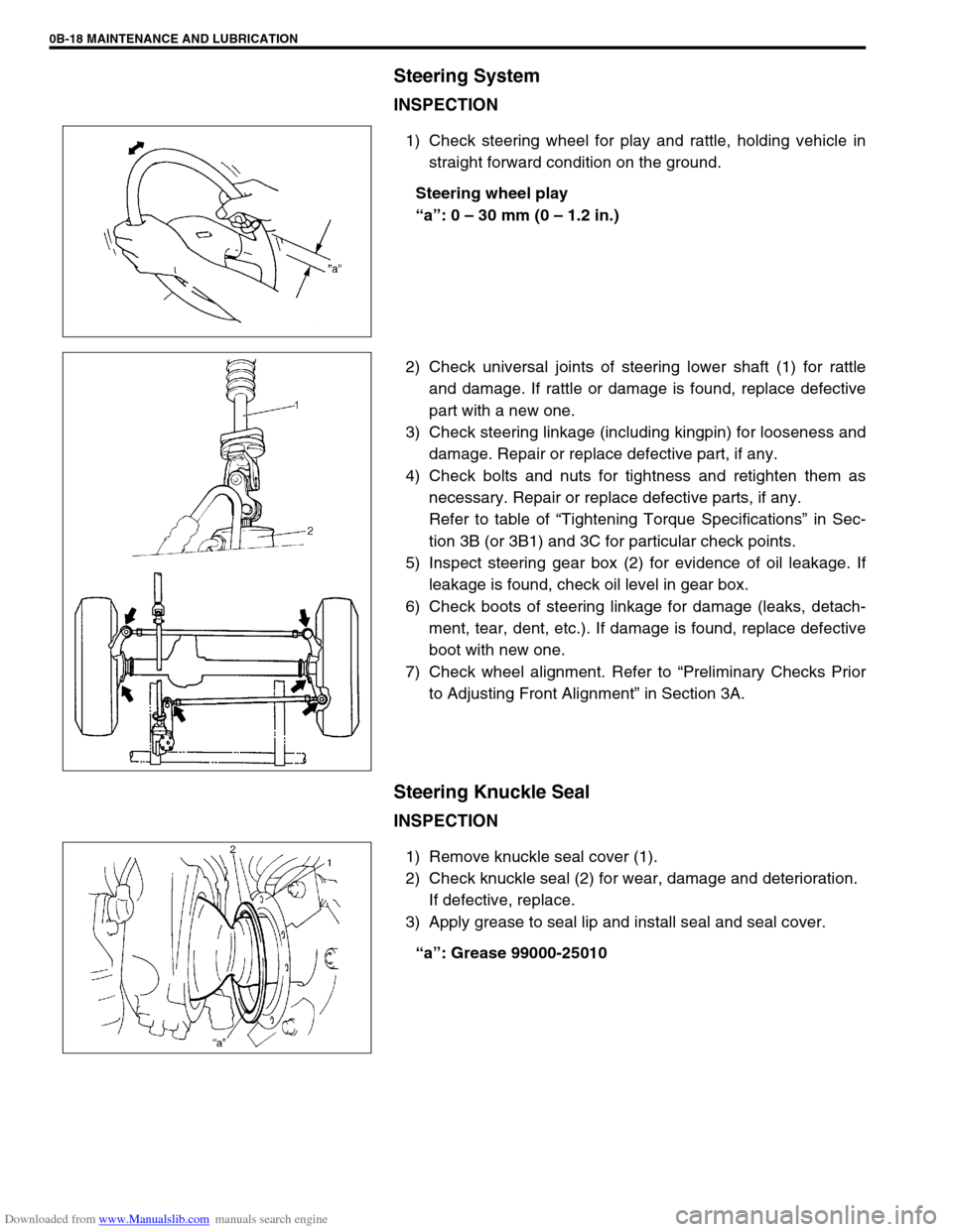
1) Check steering wheel for play and rattle, holding vehicle in
straight forward condition on the ground.
Steering wheel play
“a”: 0 – 30 mm (0 – 1.2 in.)
2) Check universal joints of steering lower shaft (1) for rattle
and damage. If rattle or damage is found, replace defective
part with a new one.
3) Check steering linkage (including kingpin) for looseness and
damage. Repair or replace defective part, if any.
4) Check bolts and nuts for tightness and retighten them as
necessary. Repair or replace defective parts, if any.
Refer to table of “Tightening Torque Specifications” in Sec-
tion 3B (or 3B1) and 3C for particular check points.
5) Inspect steering gear box (2) for evidence of oil leakage. If
leakage is found, check oil level in gear box.
6) Check boots of steering linkage for damage (leaks, detach-
ment, tear, dent, etc.). If damage is found, replace defective
boot with new one.
7) Check wheel alignment. Refer to “Preliminary Checks Prior
to Adjusting Front Alignment” in Section 3A.
Steering Knuckle Seal
INSPECTION
1) Remove knuckle seal cover (1).
2) Check knuckle seal (2) for wear, damage and deterioration.
If defective, replace.
3) Apply grease to seal lip and install seal and seal cover.
“a”: Grease 99000-25010
Page 112 of 687

Downloaded from www.Manualslib.com manuals search engine STEERING, SUSPENSION, WHEELS AND TIRES 3-3
Shimmy, Shake or
VibrationTire or wheel out of balance Balance wheels or replace tire
and/or wheel.
Loose wheel bearings Replace wheel bearing.
Loose wheel hub nuts Retighten.
Worn tie rod ends Replace tie rod end.
Worn king pin bearings or king pins Replace king pin bearing and/or
king pin.
Excessive wheel runout Repair or replace wheel and/or tire.
Blister or bump on tire Replace tire.
Excessively loaded radial runout of tire / wheel
assemblyReplace tire or wheel.
Disturbed front wheel alignment Check and adjust front wheel align-
ment.
Loose or worn steering linkage Tighten or replace steering linkage.
Loose steering gear box bolts Tighten box bolts.
Worn steering knuckle oil seal Replace.
Hard Steering
Bind in tie rod end ball studs or king pin bear-
ingsReplace tie rod end or king pin
bearing.
Disturbed front wheel alignment Check and adjust front wheel align-
ment.
Steering gear box adjustment Check and adjust steering gear
box.
Tire not adequately inflated Inflate tires to proper pressure.
Bind in steering column Repair or replace.
Low fluid level, loose drive belt or malfunction of
power steering system (if equipped with P/S)Check and correct.
Too Much Play in
SteeringWheel bearings worn Replace wheel bearing.
Steering gear box attachments loose Tighten or repair.
Steering gear box adjustments Check and adjust steering gear
box.
Worn steering shaft joints Replace joint.
Worn tie rod ends drug rod ball joints Replace tie rod end.
Worn king pin bearings or king pin Replace king pin bearing and/or
king pin.
Poor Returnability
Bind in tie rod end ball studs Replace tie rod end.
Bind in king pin bearings Replace king pin bearing.
Bind in steering column Repair or replace.
Steering gear box needing lubricant Check, repair or lubricate steering
gear box.
Disturbed front wheel alignment Check and adjust front wheel align-
ment.
Steering gear box not properly adjusted Check and adjust steering gear box
torque.
Tires not adequately inflated Adjust pressure.
Steering Noise
(Rattle or Chuckle)Loose bolts and nuts Retighten.
Broken or otherwise damaged wheel bearings Replace wheel bearing.
Worn or sticky tie rod ends Replace tire rod end.
Linkage joints needing grease Lubricate or replace. Condition Possible Cause Correction
Page 113 of 687

Downloaded from www.Manualslib.com manuals search engine 3-4 STEERING, SUSPENSION, WHEELS AND TIRES
Abnormal Noise,
Front EndWorn, sticky or loose tie rod ends, drug rod ball
joints, king pin bearings or axle shaft jointsReplace tie rod end, king pin bear-
ing or axle shaft joint.
Damaged shock absorbers or mountings Replace or repair.
Worn leading arm bushings Replace.
Worn stabilizer bar bushings Replace.
Worn Iateral rod bushings Replace.
Loose stabilizer bar Tighten bolts or replace bushes.
Loose wheel nuts Tighten wheel nuts.
Loose suspension bolts or nuts Tighten suspension bolts or nuts.
Broken or otherwise damaged wheel bearings Replace wheel bearing.
Broken suspension springs Replace spring.
Wander or Poor
Steering StabilityMismatched or uneven tires Replace tire or inflate tires to
proper pressure.
Loose king pin bearings and tie rod ends Replace king pin bearing or tie rod
end.
Faulty shock absorbers or mounting Replace absorber or repair mount-
ing.
Loose stabilizer bar Tighten or replace stabilizer bar or
bushes.
Broken or sagging springs Replace spring.
Steering gear box not properly adjusted Check or adjust steering gear box
torque.
Front wheel alignment Check and adjust front wheel align-
ment.
Erratic Steering when
BrakingWorn wheel bearings Replace wheel bearing.
Broken or sagging springs Replace spring.
Leaking wheel cylinder or caliper Repair or replace wheel cylinder or
caliper.
Warped discs Replace brake disc.
Badly worn brake linings Replace brake shoe lining.
Drum is out of round in some brakes Replace brake drum.
Wheel tires are inflated unequally Inflate tires to proper pressure.
Defective wheel cylinders Replace or repair wheel cylinder.
Disturbed front wheel alignment Check front wheel alignment
Ride Too Soft
Faulty shock absorber Replace shock absorber.
Suspension bottoms
Overloaded Check loading.
Faulty shocks absorber Replace shock absorber.
Incorrect, broken or sagging springs Replace spring.
Body Leans or Sways
in CornersLoose stabilizer bar Tighten stabilizer bar bolts or
replace bushes.
Faulty shocks absorbers or mounting Replace shock absorber or tighten
mounting.
Broken or sagging springs Replace spring.
Overloaded Check loading.
Cupped Tires
Worn wheel bearings Replace wheel bearing.
Excessive tire or wheel run-out Replace tire or wheel disc.
Tire out of balance Adjust tire balance. Condition Possible Cause Correction
Page 120 of 687

Downloaded from www.Manualslib.com manuals search engine FRONT WHEEL ALIGNMENT 3A-3
Diagnosis
Diagnosis Table
For the details, refer to “Diagnosis Table” in Section 3.
Preliminary Checks Prior To Adjusting Front Wheel Alignment
Steering and vibration complaints are not always the result of improper alignment. An additional item to be
checked is the possibility of tire lead due to worn or improperly manufactured tires. “Lead” is the deviation of the
vehicle from a straight path on a level road without hand pressure on the steering wheel. Section 3 of this man-
ual contains a procedure for determining the presence of a tire lead problem. Before making any adjustment
affecting toe setting, the following checks and inspections should be made to ensure correctness of alignment
readings and alignment adjustments:
1) Check all tires for proper inflation pressures and approximately the same tread wear.
2) Check for loose of king pin bearings. Check tie rod ends; if excessive looseness is noted, it must be cor-
rected before adjusting.
3) Check for run-out of wheels and tires.
4) Check vehicle trim heights; if out of limits and a correction is to be made, it must be made before adjusting
toe.
5) Check for loose of suspension arms.
6) Check for loose or missing stabilizer bar attachments.
7) Consideration must be given to excess loads, such as tool boxes. If this excess load is normally carried in
vehicle, it should remain in vehicle during alignment checks.
8) Consider condition of equipment being used to check alignment and follow manufacturer's instructions.
9) Regardless of equipment used to check alignment, vehicle must be on a level surface both fore and aft and
transversely.
Toe Adjustment
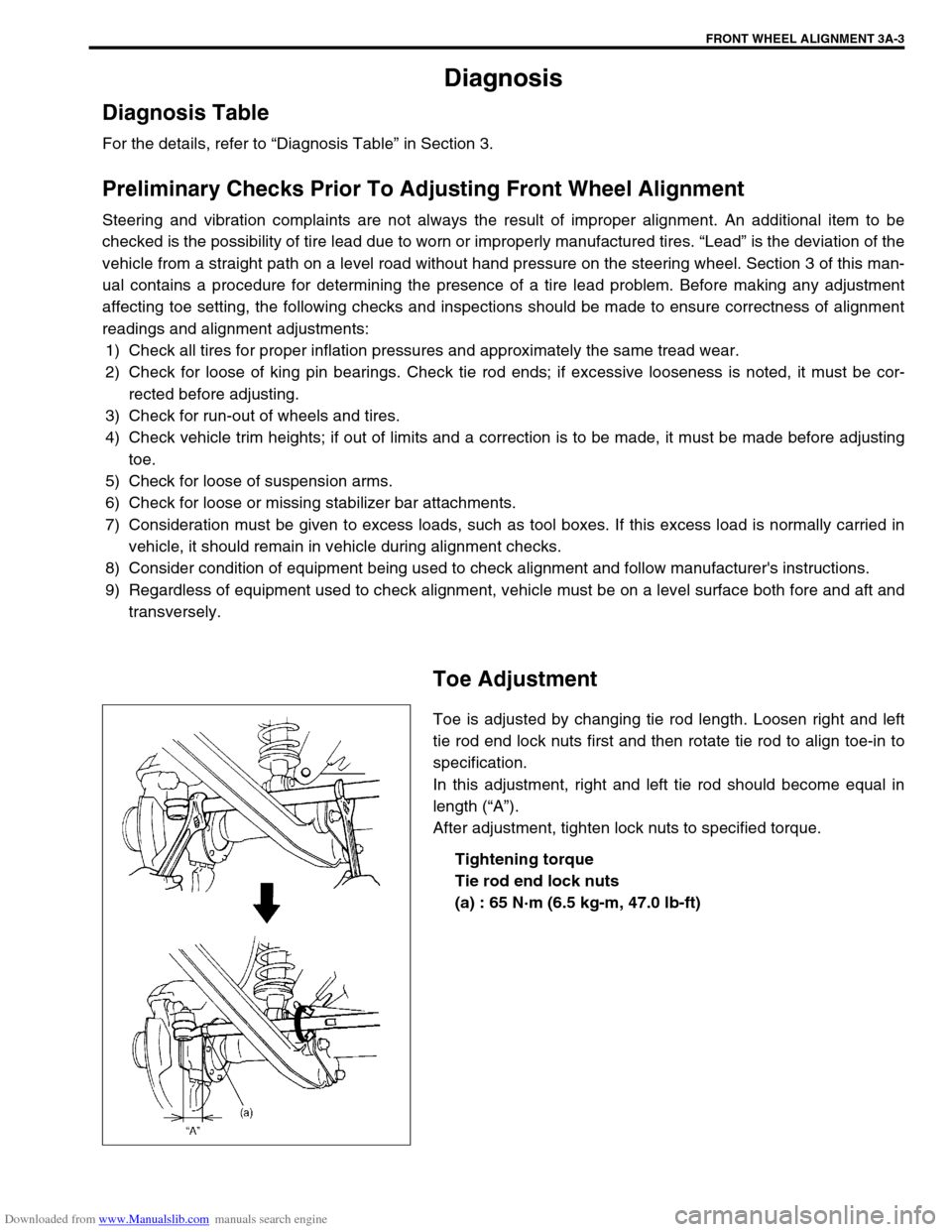
Toe is adjusted by changing tie rod length. Loosen right and left
tie rod end lock nuts first and then rotate tie rod to align toe-in to
specification.
In this adjustment, right and left tie rod should become equal in
length (“A”).
After adjustment, tighten lock nuts to specified torque.
Tightening torque
Tie rod end lock nuts
(a) : 65 N·m (6.5 kg-m, 47.0 lb-ft)